
 Open Access Article
 This Open Access Article is licensed under a
 Creative Commons Attribution 3.0 Unported Licence
The growth mechanism of calcareous deposits under various hydrostatic pressures during the cathodic protection of carbon steel in seawater
C. J. Li ab and
M. Du*b
ab and
M. Du*b
aWeifang University of Science and Technology, Shouguang 262700, P. R. China
bThe Key Laboratory of Marine Chemistry Theory and Technology, Ministry of Education, College of Chemistry and Chemical Engineering, Ocean University of China, Qingdao 266100, P. R. China. E-mail: ssdm99@ouc.edu.cn
First published on 31st May 2017
Abstract
A galvanostatic method was used to study the influence of hydrostatic pressure on the cathodic protection of carbon steel in seawater. The polarization and electrochemical behavior of Q235 carbon steel was studied after being covered with calcareous deposits. Surface analysis was performed to investigate the growth mechanism of the calcareous deposits under various hydrostatic pressures. Although there was no obvious effect of the hydrostatic pressure on the polarization potential decay, the protectiveness of calcareous deposits showed significant variation under the different pressures. The results of electrochemical impedance spectroscopy (EIS) and linear polarization resistance (LPR) indicate that the electrochemical reaction resistance Rct on the polarized metal surface initially increased with the increasing pressure and then decreased, with a maximum value at 2 MPa. The protection factor Fp of the deposits decreased when the pressure was higher than 2 MPa. Scanning electron microscopy (SEM) and X-ray diffraction (XRD) analyses illustrated that parts of the calcium lattice positions were substituted by magnesium ions in the initial crystallization of calcium carbonate under 5 MPa pressure or even higher, which resulted in a crystal structure transformation from aragonite to dolomite. The order degree δ of dolomite decreased under high pressure due to the low free energy of the lattice.
1. Introduction
Cathodic protection (CP) has been widely used for corrosion control in a marine environment, especially for large static structures such as sub-sea pipelines for oil and gas exploration. In recent years, there has been a substantial increase in energy exploration and production in deep water regions. These expanded operations have involved many new challenges, such as corrosion and materials technology. Since carbon steel is usually the major construction material used for production facilities, good corrosion control and a reliable CP system is essential for safe long-term operation, which is required for the development the deep water resources.In order to optimize the CP designs for deep water, a thorough understanding of the greater depth environmental effects on the CP process is required. There are significant variations in a series of environmental parameters at great depth, such as the temperature, dissolved oxygen, pH, flow velocity and so on. The variations can severely impact the CP process and have drawn substantial attention and research.1–8 As one of the most influential parameters, hydrostatic pressure is directly proportional to depth and increases by about 0.1 MPa for each 10 m increase in the water depth. However, previous research activity has mostly addressed the other influential variables (e.g. temperature, dissolved oxygen, flow velocity, etc.), still the present state-of-knowledge falls short of the hydrostatic pressure influence on deep water CP. For example, Hartt and the co-workers studied the deep water CP by laboratory simulations and field experiments at a 899 m Gulf of Mexico site, and it indicated that the current density demand was relatively high in deep water.9,10 This was consistent with the results previously reported by England and Heidersbach.11 However, the presented data combined the influences of temperature and pressure and lacked the study on the single factor of pressure. Fischer et al. proposed a semi-empirical formula on the basis of CP electrochemical theory and field experiments, however, the parameter of pressure was not included.12
Additionally, calcareous deposits will form on the protected steel surface after CP in seawater. This is because of hydrogen evolution and oxygen reduction reactions:
| H2O + 1/2O2 + 2e− → 2OH− | (1) |
| 2H2O + 2e− → 2OH− + H2 | (2) |
Due to the generation of OH−, the magnesium ions will react with OH− and are deposited as brucite of Mg(OH)2 on the steel surface. Further, as the variation of pH near the steel surface, the inorganic carbonic equilibrium will be disrupted, leading to the concentration of carbonate ions and the precipitation of CaCO3.
| Mg2+ + 2OH− → Mg(OH)2 | (3) |
| Ca2+ + CO32− → CaCO3 | (4) |
As these non-conductive deposits progressively cover the surface, the flux of dissolved oxygen from seawater towards the steel surface is limited. In addition, the overall rate of the cathodic reaction (eqn (1)) decreases, leading to a reduction in the CP current density required and consumption the sacrificial anode.13–17 Therefore, knowing the formation mechanism and how to promote the quality of the calcareous deposits is important for the design and prediction of a CP system. However, the main attention for the hydrostatic pressure effect on CP has been focused on the variation of current density and there is a lack of studies on the calcareous deposits formation under deep water and high hydrostatic pressure. For example, Hu et al. studied the effect of cyclic hydrostatic pressure on the sacrificial anode CP, while little attention has been devoted to the formation of calcareous deposits on the cathode surface.18 Thomason and Fischer suggested that it was not the hydrostatic pressure that causes the compound variation of calcareous deposits in deep water but the temperature and flow velocity, and the growth of calcareous deposits was mainly controlled by the ocean sites and field environments.19 Tawns and Oakley studied the CP at a simulated depth of 2500 m and found that thick but poorly adherent calcareous deposits were formed by high-pressure CP after 30 d, and the protectiveness was not as effective as that found at atmospheric pressure.20 While there was a lack of research on the structure and morphology of the calcareous deposits in their presented work.
To date, most studies on the hydrostatic pressure effects on CP have been devoted to field experiments in deep water. Actually, there are different environmental conditions in different marine regions although at the same depth. Therefore, various conclusions have been drawn for the deep water CP process. Additionally, there are complicated environmental factors in the field sites, which will have a multiple and combined impact on the CP process. In addition, it is difficult to only study the influence of hydrostatic pressure on CP based on the field experiments results because of the interference of other factors, e.g. temperature and flow velocity. Therefore, the single factor experiment of CP should be performed to eliminate the disturbance of the other environmental factors from hydrostatic pressure in deep water.
In this paper, the effect of hydrostatic pressure on carbon steel CP was studied using a single factor experiment. Specific attention has been focused upon the electrochemical behaviour variation on the carbon steel surface under various hydrostatic pressures after CP, which was studied using EIS and LPR measurements. The growth mechanism of the calcareous deposits was discussed by SEM and XRD analysis, and the crystal structure transformation of CaCO3 under high pressure was investigated. The presented results may be helpful for the supplementation and perfection of CP theory in deep water.
2. Experimental
Natural seawater was used in all our experiments, of which the salinity was 32 and pH was 8.1 from Maidao, a coastal scientific station in Qingdao, China. The seawater was filtered through 0.7 μm pore-size glass fiber filters to clear the marine growth before the CP experiments. Carbon steel Q235 was used as the working electrode, with an approximate composition (in weight%) of: 99.32% Fe, 0.18% C, 0.02% Si, 0.45% Mn, 0.02% S, and 0.01% P. The plate metal samples were embedded in epoxy resin, leaving a geometrical surface area of 1 cm2 exposed to the electrolyte and then polished with 600, 1000, 2000-grit paper in sequence, followed by ultrasonic cleaning and air-dried treatment prior to insertion in the test cell. The potentials were measured versus a kind of all solid-state Ag/AgCl reference electrode and were calibrated using a saturated calomel electrode (SCE) after the experiments. A large mixed metal oxide (MMO) grid was used as the counter electrode.The hydrostatic pressure apparatus is shown in Fig. 1. The hydrostatic pressure P was controlled to 0.1, 1, 2, 5 and 10 MPa during the CP process, respectively. The pressure is equivalent to a water depth of 0, 100, 200, 500 and 1000 m. The temperature was controlled at 25 ± 1 °C during the experimental process, in order to eliminate the influence of temperature changes on the CP process. The dissolved oxygen was of the natural concentration in seawater at the experimental temperature (approximately 6–7 mg L−1). A galvanostatic polarization method was used to perform the CP experiments using a mean current density of 200 mA m−2. The working electrode was polarized for 168 h.
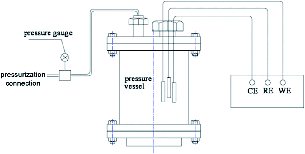 | ||
| Fig. 1 A schematic of the electrochemical cell used for controlling the hydrostatic pressure. | ||
In situ electrochemical measurements were carried out using an IM6e (ZAHNER, Germany) electrochemistry workstation after the galvanostatic polarization. A delay time of 40 minutes was set before the measurements were started in order to stabilize the electrode potential. A potentiodynamic polarization scan was performed at a scan rate of 0.1 mV s−1 in the range of ±10 mV at an open circuit potential (OCP). EIS measurements over a frequency range from 100 kHz to 10 mHz followed the potentiodynamic polarization scan. In order to resist the large interface impedance caused by the deposit formation and enhance the frequency response characteristics, a larger perturbation amplitude of 10 mV at an OCP was employed, other than 5 mV that is often used in conventional EIS measurements.
After the electrochemical measurements, the electrodes were taken out and rinsed with deionized water to clear away the salt (mainly of NaCl). Then ex situ SEM observations using a JEOL JSM-6700F scanning electron microscope were performed to characterize the deposits, whose chemical compositions were analysed using energy dispersive X-ray spectroscopy (EDX). The EDX investigation zone was the entire exposed surface of the electrode. XRD was also involved to analyse the crystalline form of the deposits, performed on a D8 ADVANCE apparatus at a scanning rate of 4° min−1 and range of 10–80°.
3. Results and discussion
3.1. Potential decay at various hydrostatic pressures
The potential variation trends of the electrodes were recorded versus the polarized time under different hydrostatic pressures to investigate the protection status.As shown in Fig. 2, almost the same variation trends were shown for the potential decay under different hydrostatic pressures. The electrodes potentials shifted negatively versus the protection time at the very beginning of the polarization of 60 h, and then stabilized gradually. This was because of the formation of the calcareous deposits on the electrode surface, which can decrease the diffusion rate of oxygen to the metal-solution surface and inhibit the oxygen reduction reaction. Less oxygen diffusion to the steel surface and the accumulation of excess charge causes the steel potential to shifting negatively at the beginning of the polarization of 60 h. When the potential was more negative than −1.1 V (vs. SCE), the non-diffusion-controlled hydrogen evolution reaction became the dominant cathodic reaction, which was limited by the charge transfer. Therefore, the potential variations were not affected by the electrode surface status and the potential profiles almost overlapped with each other under different pressures during the later CP stage. This revealed that the protection potential of carbon steel was independent of the hydrostatic pressure.
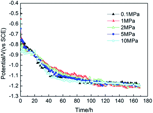 | ||
| Fig. 2 The potential decay curves vs. time under various hydrostatic pressures under galvanostatic polarization. | ||
3.2. EIS measurements
EIS measurements were performed in situ after the electrodes were polarized for 168 h. As a comparison, electrodes without polarization (blank) were also measured under various hydrostatic pressures. The Nyquist diagrams of the electrodes under the different pressures are shown in Fig. 3.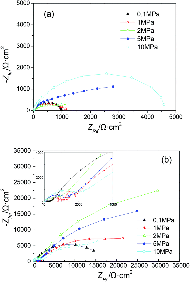 | ||
| Fig. 3 Nyquist diagrams under various hydrostatic pressures: (a) without polarization (blank) and (b) with galvanostatic polarization for 168 h. | ||
For bare steel (blank), an obvious increase in the capacitive loop size with increasing hydrostatic pressure was observed (Fig. 3a), revealing an increase in the interfacial charge transfer rate. This may be caused by the higher activation energy under higher pressure.19 Nevertheless, the Nyquist diagrams of the electrodes after polarization showed more complex cases under the different hydrostatic pressures (Fig. 3b). The capacitive loop size initially increased with increasing pressure and then began to decrease, displaying a maximum value under a pressure of 2 MPa. All the Nyquist diagrams can be characterized by two capacitive loops with a supplementary loop appeared in the high frequency region. Additionally, the loop size in the high frequency region showed a relatively regular change, increasing with the hydrostatic pressure. This may be due to the higher electrochemical reaction resistance under high pressure, which was controlled by the activation energy. For all of the hydrostatic pressures studied, the capacitive loop observed at atmospheric pressure showed the smallest size. The variation of the loop size may be attributed to the increasing activation energy under higher pressure, on the other hand, it may be attributed to the formation of calcareous deposits with different compactness and protectiveness under the different pressures.
The equivalent circuit of impedance for bare steel can be described as a resistance corresponding the charge transfer resistance Rct in parallel to the double layer capacitance Cdl, and these two elements are in series to an electrolyte resistance Re (Fig. 4a).
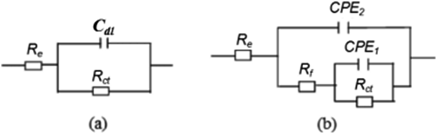 | ||
| Fig. 4 Equivalent circuit diagram: (a) bare steel and (b) electrode covered by calcareous deposits. | ||
Further, the impedance for the polarized electrodes can be illustrated using a five-element model (Fig. 4b), describing the porous calcareous deposits formation on the electrode surface. A resistance corresponding to the charge transfer resistance, Rct, at the pores bottom is placed in parallel to a constant phase element, CPE1. The constant phase element (CPE) is defined in the impedance representation as:
| Z(ω) = Z0(jω)−n | (5) |
| P (MPa) | Rs (Ω cm2) | CPE1 (μF cm−2) (n1) | Rf (Ω cm2) | CPE2 (μF cm−2) (n2) | Rct (Ω cm2) |
|---|---|---|---|---|---|
| 0.1 | 1.498 | 120 (0.7240) | 317 | 8.73 (0.6553) | 20![[thin space (1/6-em)]](https://www.rsc.org/images/entities/char_2009.gif) 156 156 |
| 1 | 1.979 | 80.80 (0.6327) | 1778 | 21.40 (0.2988) | 36060 |
| 2 | 1.54 | 104 (0.7507) | 1843 | 34.60 (0.5982) | 74700 |
| 5 | 1.48 | 139 (0.6745) | 1780 | 10.20 (0.6487) | 53627 |
| 10 | 2.21 | 133.60 (0.5143) | 1762 | 2.26 (0.8482) | 28219 |
As can been seen from the fitted results, the value of Rf increased under higher hydrostatic pressures and showed the smallest value under atmospheric pressure. One reason was that the transfer resistance of ions in the deposits thin pores increased under higher pressures, which may be due to the different deposit structures and compactness. Meanwhile, the charge transfer resistance Rct increased greatly with increasing pressure. However, when the pressure was higher than 2 MPa, Rct began to decrease. The decreasing Rct under a certain high pressure revealed the decreasing protective properties of the calcareous deposits, which was constant with the research results of Tawns and Oakley.20 This may be attributed to the higher solubility of CaCO3 under higher pressures and less deposit generation,6 and it may also be due to the transformation of the crystal morphology under high pressure.
3.3. LPR measurements
Linear polarization resistance (Rp) is commonly used to calculate the corrosion current density of steel and a high value of Rp is generally accepted as a low corrosion rate. As the calcareous deposits are developed on the steel surface after CP, the corrosion rate of steel will decrease under the open circuit conditions due to the deposits protection. Meanwhile, the larger value of Rp indicates the lower corrosion rate, which corresponds to the more compact deposit precipitation and efficient protection.LPR tests were performed in situ at the OCP and the value of Rp was obtained by fitting the linear polarization curve. The linear polarization resistance of bare steel for blank (Rp0) was also obtained under various hydrostatic pressures (Fig. 5a).
 | ||
| Fig. 5 (a) Rp0 and Rp vs. P and (b) Fp vs. P after galvanostatic polarization for 168 h. | ||
Due to the increasing activation energy under high pressure, Rp0 increased linearly with an increase in the hydrostatic pressure. The value of Rp after polarization initially increased and then decreased, with a maximum value at 2 MPa. This was consistent with the results observed for the capacitive loop size in the EIS analysis.
In order to study the calcareous deposits influence on the polarization resistance of the steel electrode after CP, the environmental background value is first deducted, which was induced by the ambient conditions of the different hydrostatic pressures. Hence, the protection factor (Fp) parameter was proposed to evaluate the calcareous deposits protection capability,22,23 defined by the equation Rp/Rp0 − 1. It was considered that the Fp valve could present the growth of the steel polarization resistance induced by calcareous deposit precipitation when compared with bare steel with no deposits. The Fp valves of the electrodes under various pressures after 168 h of polarization are shown in Fig. 5b. The variation of Fp presents a similar trend to that observed for Rp. However, there was an even smaller value of Fp at 5 and 10 MPa than that found under ambient pressure, revealing a decrease in the protective properties of the calcareous deposits under certain high hydrostatic pressures.
3.4. Morphological characteristics
In order to investigate the calcareous deposits formation on the electrode surface during CP under various hydrostatic pressures, SEM observations were performed after 168 h of polarization and are shown in Fig. 6. All the electrodes surfaces were covered by calcareous deposits after CP under various pressures, while exhibiting different morphological characteristics. Generally, an increase in the deposited particles size have been observed with increasing hydrostatic pressure. The deposits show the typical cauliflower shape crystals of aragonite under most of the experimental pressure conditions studied. However, in addition to the aragonite (Fig. 6e, crystal-1), extraordinary crystals with a pyramidal shape (Fig. 6e, crystal-2) were obtained under a pressure of 10 MPa.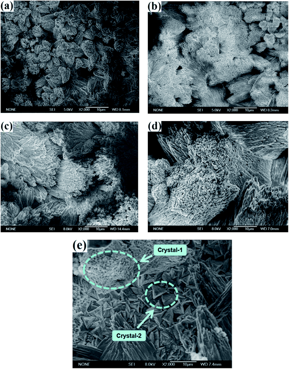 | ||
| Fig. 6 SEM observations of the calcareous deposits under various hydrostatic pressures after galvanostatic polarization for 168 h: (a) 0.1 MPa, (b) 1 MPa, (c) 2 MPa, (d) 5 MPa and (e) 10 MPa. | ||
The SEM images in Fig. 6 are at 2000 times magnification of the narrow focus ranges. A lower magnification of 500 times was further used to obtain a greater field of view, in order to confirm the crystals structures deposited on the whole electrodes surfaces and investigate the transformation mechanism for the two kinds of crystals observed under the different pressures. The coupled growth of the cauliflower and pyramidal crystals was revealed not only under a pressure of 10 MPa, but also at 5 MPa (Fig. 7a). While the intergrowth crystals were not found under the other pressures studied. XRD analysis was performed to study the crystalline structures of the two kinds of deposits. The results illustrated that the pyramidal crystals were the dolomite of CaMg(CO3)2 and not the calcite of CaCO3 with a cubic structure, which normally forms at low temperature.22,24 Generally, temperature was considered as the dominant factor for controlling the CaCO3 crystal form in the CP process. In addition, CaCO3 was generated in the form of aragonite when the temperature is higher than 20 °C, while calcite is formed at lower temperatures,6,22,25 while the other environmental parameters, such as dissolved oxygen, pH and salinity, have no obvious influence on form of the CaCO3 crystals. Actually, the experiments here were all performed at 25 °C. Therefore, it was believed that the formation of dolomite at ambient temperature was attributed to the high hydrostatic pressure. Additionally, it is generally believed that magnesium ions were easily adsorbed to the calcite surface and involved in the crystallization process, which would restrain the calcite growth. In addition, it had no effect on the growth of aragonite.25–29 However, it has been revealed distinctly that the magnesium ions participated in the crystallizing kinetics of aragonite under higher hydrostatic pressure in our experiments, which has been rarely reported before.
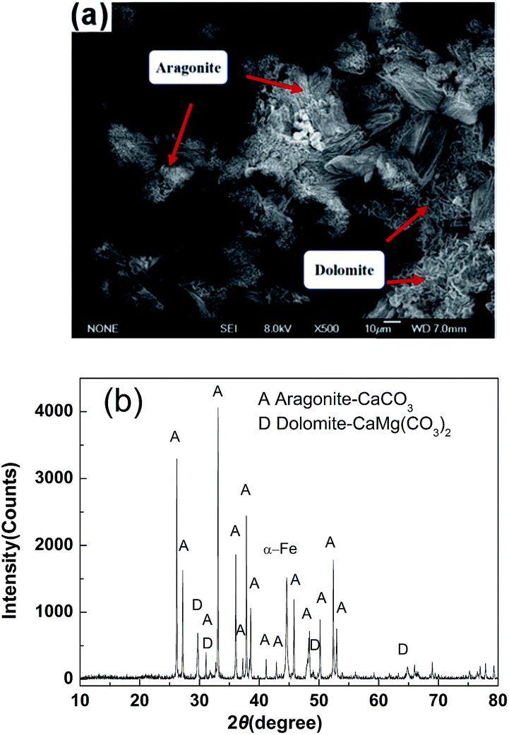 | ||
| Fig. 7 (a) SEM observations and (b) XRD results for the calcareous deposits under 5 MPa after 168 h of galvanostatic polarization. | ||
The reason for the formation of dolomite is believed to be due to the magnesium ions easily occupying the positions of the calcium ions in the CaCO3 lattice under high pressure due to their smaller ionic radius, leading to the crystallization of CaMg(CO3)2 (Fig. 8). Besides, it can be seen that the dolomite was covered by aragonite, revealing the dolomite was initially deposited and then the aragonite. Therefore, the magnesium ions only participate in the early stage of CaCO3 crystallization during the CP process. In the later stages, the crystallization of CaCO3 needs to overcome a smaller thermodynamic energy barrier due to the earlier deposited dolomite acting as a crystal nucleus.
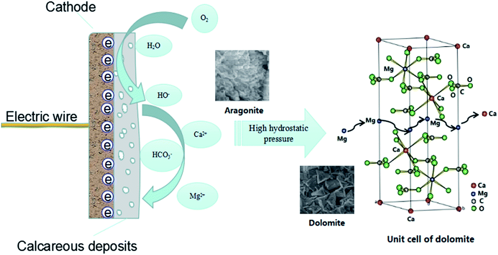 | ||
| Fig. 8 A schematic of the transformation of calcium carbonate under high hydrostatic pressure. | ||
Generally, the order degree (δ) is used to describe the arrangement of Ca2+ and Mg2+ in the dolomite crystal structure. There is the same number of Ca2+ and Mg2+ in an ideal dolomite structure, in which the Ca2+, Mg2+ and CO32− ions are alternately arranged in the (00i) direction. The δ can be expressed by the reflective intensity ratio of the (015) and (110) crystal planes, which is δ = I(015)/I(110).30 The calculated value of δ for the dolomite structure under 5 MPa and 10 MPa was 0.45 and 0.08, respectively, illustrating a decrease in δ under the higher hydrostatic pressures. This can be explained by the entropy increase in the process, which was caused by the increased disorder of the cation distribution in the dolomite crystal structure. The decrease in δ will be beneficial to decrease the free energy of the dolomite lattice under high pressure.
In order to investigate the atomic molar ratio of Ca/Mg in the deposits formed under the different pressures, EDX was performed to verify the participating behavior of the magnesium ions during CaCO3 deposition under high pressure. The results are shown in Table 2. This reveals that the fraction of magnesium increased upon increasing the hydrostatic pressure. In addition, an obviously decrease in the Ca/Mg ratio confirmed that more magnesium ions participated in the CaCO3 crystallization process under the higher pressures, leading to the deposition of dolomite and a decrease in δ.
| P (MPa) | Ca fraction (mol%) | Mg fraction (mol%) | Atomic ratio of Ca/Mg |
|---|---|---|---|
| 0.1 | 16.85 | 0.07 | 240.71 |
| 1 | 16.92 | 0.16 | 105.75 |
| 2 | 17.38 | 0.24 | 74.42 |
| 5 | 17.48 | 0.76 | 23.00 |
| 10 | 21.70 | 1.55 | 14.00 |
In summary, the morphology analysis echoed the results of the electrochemical measurements. Due to the higher solubility of the calcareous deposits under high hydrostatic pressure, a lower amount of deposits were generated on the steel surface. Additionally, the crystal transformation of the calcium carbonate from aragonite to dolomite caused a decrease in the deposits compactness and protectiveness. Both factors were attributed to the decrease in the capacitive loop size observed in EIS and Fp in the LPR results under high pressure. Therefore, a higher CP current density may be needed under a high hydrostatic pressure and in deep water.
4. Conclusions
In this paper, specific attention has been focused upon the influence of hydrostatic pressure on the CP process of carbon steel and also the mechanism for calcareous deposition. The CP process was monitored under various pressures. The electrochemical characteristics of the electrodes surfaces were studied after the CP process. The transformation of the calcium carbonate crystals from aragonite to dolomite was observed and confirmed under high hydrostatic pressures. The following conclusions are made:(1) The protection potential of carbon steel was independent of the hydrostatic pressure in the investigated range from 0.1 MPa to 10 MPa.
(2) The EIS results revealed that the capacitive loop size initially increased with increasing pressure due to the increasing activation energy needed and then began to decrease, which was attributed to the reduction of the deposit quality and protectiveness. The fitting results indicated a maximum value of the Rct was obtained at 2 MPa.
(3) The LPR results demonstrated that the maximum protection factor Fp was obtained at 2 MPa, where the deposits exhibited the best protectiveness. When the pressure was higher than 5 MPa, the deposits protective capability was even worse than that found at ambient pressure.
(4) The morphology analysis echoed the results of the electrochemical measurements. The decrease in Rct and Fp under high pressure was attributed to the higher solubility of CaCO3 and the transformation of its crystal form. The atomic molar ratio of Ca/Mg in the deposits decreased with an increase in the hydrostatic pressure. When the pressure was higher than 5 MPa, the magnesium ions can occupy the positions of calcium ions in the CaCO3 lattice because of the smaller ionic radius, leading to the crystallization of CaMg(CO3)2. Due to the increase in entropy during the process and the decrease in the dolomite lattice free energy, the order degree (δ) of dolomite decreased under high pressure.
Acknowledgements
The authors gratefully acknowledge the financial support of this project by the National Natural Science Foundation of China (No. 41576076), Project of Shandong Province Higher Educational Science and Technology Program (No. J15LA62) and Doctoral Fund Project of Weifang University of Science and Technology (No. 2017BS07).References
- W. H. Hartt, Corrosion, 2012, 68, 1063–1075 CrossRef CAS.
- C. Rousseau, F. Baraud, L. Leleyter, M. Jeannin and O. Gil, Corros. Sci., 2010, 52, 2206–2218 CrossRef CAS.
- K. J. Kim and W. H. Hartt, Characteristics of cathodic protection and calcareous deposits for type 316L stainless steel in simulated deep sea conditions, in CORROSION 2006, NACE Conference, NACE International, Houston, TX, San Diego, U.S, March 12–16, 2006 Search PubMed.
- C. Barchiche, C. Deslouis, O. Gil, P. Refait and B. Tribollet, Electrochim. Acta, 2004, 49, 2833–2839 CrossRef CAS.
- L. Beaunier, C. Gabrielli, G. Poindessous, G. Maurin and R. Rosset, J. Electroanal. Chem., 2001, 501, 41–53 CrossRef CAS.
- J. F. Yan, R. E. White and R. B. Griffin, J. Electrochem. Soc., 1993, 140, 733–741 CrossRef CAS.
- K. E. Mantel, W. H. Hartt and T. Y. Chen, Corrosion, 1992, 48, 489–500 CrossRef CAS.
- R. U. Lee and J. Ambrose, Corrosion, 1988, 44, 887–891 CrossRef CAS.
- S. Chen and W. H. Hartt, Corrosion, 2002, 58, 38–48 CrossRef CAS.
- S. Chen, W. H. Hartt and W. Wolfson, Corrosion, 2003, 59, 721–732 CrossRef CAS.
- H. R. England and R. H. Heidersbach, The Effects of water depth on cathodic protection of steel in seawater, in Proceedings of the 13th Annual OTC, Offshore Technology Conference, OTC, Houston, TX, U.S, May 4–7, 1981, pp. 379–384 Search PubMed.
- K. P. Fischer, B. P. Espelid and B. P. Schei, A review of CP current demand and anode performance for deep water, in CORROSION 2001, NACE Conference, NACE International, Houston, TX, U.S, March 11–16, 2001 Search PubMed.
- M. R. Belmonte, J. T. P. Quiroz, B. V. Salas, M. M. Madrid, A. T. Acosta, J. P. Calderón and M. S. Wiener, Anti-Corros. Methods Mater., 2013, 60, 160–167 CrossRef CAS.
- C. Rousseau, F. Baraud, L. Leleyter, M. Jeannin and O. Gil, Electrochim. Acta, 2009, 55, 196–203 CrossRef CAS.
- C. Barchiche, C. Deslouis, O. Gil, S. Joiret, P. Refait and B. Tribollet, Electrochim. Acta, 2009, 54, 3580–3588 CrossRef CAS.
- A. Benedetti, L. Magagnin, F. Passaretti, E. Chelossi, M. Faimali and G. Montesperelli, Electrochim. Acta, 2009, 54, 6472–6478 CrossRef CAS.
- S. Rossi, P. L. Bonora, R. Pasinetti, L. Benedetti, E. Sacco and M. Draghetti, Corrosion, 1998, 54, 1018–1025 CrossRef CAS.
- S. N. Hu, T. Zhang, Y. W. Shao, G. Z. Meng and F. H. Wang, Anti-Corros. Methods Mater., 2011, 58, 238–244 CrossRef CAS.
- W. H. Thomason and K. P. Fischer, Cathodic protection of steel structures in deep water: A Review, in Proceedings of the 23rd Annual Offshore Technology Conference, Offshore Technology Conference OTC, Houston, TX, U.S, May 6–9, 1991, pp. 243–252 Search PubMed.
- A. Tawns and R. Oakley, Cathodic protection at a simulated depth of 2500 m, in CORROSION 2000, NACE Conference, NACE International, Orlando, Houston, TX, U.S, March 26–31, 2000 Search PubMed.
- B. Wang, M. Du, J. Zhang and C. J. Gao, Corros. Sci., 2011, 53, 353–361 CrossRef CAS.
- C. J. Li, M. Du, J. Qiu, J. Zhang and C. J. Gao, Acta Metall. Sin., 2014, 27, 131–139 CrossRef CAS.
- C. J. Li, M. Du and R. J. Gao, J. Ocean Univ. China, 2017, 16, 243–248 CrossRef CAS.
- C. Deslouis, D. Festy, O. Gil, G. Rius, B. Touzain and S. Tribollet, Electrochim. Acta, 1998, 43, 1891–1901 CrossRef CAS.
- S. H. Lin and S. C. Dexter, Corrosion, 1988, 44, 615–622 CrossRef CAS.
- T. Chen, A. Neville and M. Yuan, J. Cryst. Growth, 2005, 275, e1341–e1347 CrossRef CAS.
- A. Neville and A. P. Morizot, J. Cryst. Growth, 2002, 243, 490–502 CrossRef CAS.
- C. Barchiche, C. Deslouis, D. Festy, O. Gil, P. Refait, S. Touzain and B. Tribollet, Electrochim. Acta, 2003, 48, 1645–1654 CrossRef CAS.
- C. Deslouis, D. Festy, O. Gil, V. Maillot, S. Touzain and B. Tribollet, Electrochim. Acta, 2000, 45, 1837–1901 CrossRef CAS.
- J. R. Goldsmith and D. L. Graf, J. Geol., 1958, 66, 678–693 CrossRef CAS.
| This journal is © The Royal Society of Chemistry 2017 |