 Open Access Article
Creative Commons Attribution 3.0 Unported Licence
Cost-effective synthesis of bamboo-structure carbon nanotubes from coal for reversible lithium storage†
Jun Li,
Yali Cao ,
Luxiang Wang and
Dianzeng Jia*
Key Laboratory of Energy Materials Chemistry, Ministry of Education, Key Laboratory of Advanced Functional Materials, Institute of Applied Chemistry, Xinjiang University, Autonomous Region, Urumqi, Xinjiang 830046, China
First published on 11th July 2017
Abstract
Carbon nanotubes (CNTs) with special structures offer great benefits for energy storage applications. Herein, we reported the facile and cost-effective synthesis of bamboo-structure CNTs (B-CNTs) using coal as the precursor through an effective arc discharge process. When evaluated as an anode material for lithium-ion batteries, the B-CNTs afford a high reversible capacity of 450.1 mA h g−1, even after 100 cycles, as well as excellent rate performance over widely varied current densities, far superior to those of commercially available graphite anodes.
1. Introduction
Carbon nanotubes (CNTs) offer great advantages as a promising anode material for lithium-ion batteries (LIBs) because of their fascinating properties.1–3 The reversible lithium storage property has been demonstrated to be further improved by the design and synthesis of CNTs with special structures, which promised to fulfill the increasing demand of high-performance energy storage materials.4–8 A typical example of such a structure is the bamboo-structure CNTs (B-CNTs). Previous studies have shown that the bamboo-structure CNTs where the internal compartments can offer an increased hosting sites for lithium-ions, decreased the lithium ion diffusion distances, enlarged electrode–electrolyte contact area and buffer volume for expansion–contraction.9–12 However, one prerequisite to promote the real applications of these B-CNTs is to effectively synthesize such unique structures at low cost. The B-CNTs can either be synthesized with delicately prepared catalysts through chemical vapor process or using dual template method involving Rayleigh-instability transform.13–15 These meticulously designed process will undoubtedly add extra cost to the product. As a result, the cost-effectively synthesis of B-CNTs still remains challenge. The natural materials derived from biomass have been demonstrated as one kind of widely available raw materials for CNTs synthesis.16–19 Among various precursors, coal represents the cheapest natural materials because of abundant reserves. For example, the confirmed reserve globally is over 1000 billion tonnes and China affords a production capacity of 1.4 billion tonnes yearly.20 The cost of B-CNTs can be significantly reduced if coal is facilely converted into B-CNTs. There have been several studies on the feasibility of CNTs synthesis from coal and exploring the potential for large scale production.21–23Herein, we report an efficient and cost-effective synthesis of B-CNTs using coal as the precursors via an arc-discharge process. When evaluated as an anode materials for LIBs, the B-CNTs deliver outstanding performance, far superior to the commercially available graphite anodes. This work may inspire new possibilities to massively synthesize CNTs with special structures, paving the way for the real application of these novel carbon nanomaterials.
2. Experimental
The bamboo-structure carbon nanotubes (B-CNTs) were synthesized by arc discharge method using coal as the starting materials. The set-up of DC apparatus is shown in Fig. S1.† The arcing experiment was described in ESI.† After arc evaporation, the B-CNTs were collected from the surface of cathode and the B-CNTs yield was about 19.81%. The morphology and microstructure of the as-grown B-CNTs were characterized by field emission scanning electron microscopy (FE-SEM; Hitachi S-4800) with energy dispersive spectroscopy (EDS), transmission electron microscope (TEM; Hitachi H-600), high-resolution transmission electron microscopy (HRTEM; JEOL JEM-2100), X-ray diffraction (XRD; Bruker D8, using filtered Cu Kα radiation), Raman spectra (Raman; Bruker Senterra R200-L spectrometer, 532 nm), X-ray photoelectron spectroscopy (XPS; PHI 5000 Versa Probe), Brunauer Emmett Teller (BET, Autosorb iQ2-MP) surface area and thermogravimetric analysis (TGA, STA 449F3).For the fabrication of electrodes, a conventional coating method was employed. A slurry consisting of the as-grown B-CNTs (85 wt%), acetylene black (5 wt%), and PVDF (10 wt%) in NMP uniformly spread onto a Cu foil, and then dried under vacuum at 80 °C for 12 h. The active material areal mass loading of the electrodes was 0.7–1.8 mg cm−2 and the total surface area of the electrode is 1.13 cm2. Coin-type cells (2032) were assembled with a solution of 1 M LiPF6 in a 1![[thin space (1/6-em)]](https://www.rsc.org/images/entities/char_2009.gif) :
:![[thin space (1/6-em)]](https://www.rsc.org/images/entities/char_2009.gif) 1 (volume ratio) mixture of ethylene carbonate and dimethyl carbonate as the electrolyte (the amount of electrolyte added is 30 μL), a Celgard 2300 microporous polyethylene membrane as the separator, and a lithium disk as the counter electrode. All cells were assembled in an argon-filled glove box, where water and oxygen concentration were kept less than 5 ppm. All electrochemical tests were carried out at room temperature. Cyclic voltammogram (CV) were collected over a voltage range of 0 to 3 V at a scan rate of 0.1 mV s−1 using an electrochemical workstation (Chenhua, CHI660D, China). Galvanostatic charge and discharge cycling were performed between 0 and 3 V on a battery test instrument (CT2001A, Land, China). Electrochemical impedance spectroscopy (EIS) was measured on a Zahner Elektrik (Zennium, Zahner, Germany) electrochemical workstation in the frequency range from 0.1 to 100 kHz, which applied a discharge potential equal to the open circuit voltage of the cell and an alternating current oscillation of 5 mV.
1 (volume ratio) mixture of ethylene carbonate and dimethyl carbonate as the electrolyte (the amount of electrolyte added is 30 μL), a Celgard 2300 microporous polyethylene membrane as the separator, and a lithium disk as the counter electrode. All cells were assembled in an argon-filled glove box, where water and oxygen concentration were kept less than 5 ppm. All electrochemical tests were carried out at room temperature. Cyclic voltammogram (CV) were collected over a voltage range of 0 to 3 V at a scan rate of 0.1 mV s−1 using an electrochemical workstation (Chenhua, CHI660D, China). Galvanostatic charge and discharge cycling were performed between 0 and 3 V on a battery test instrument (CT2001A, Land, China). Electrochemical impedance spectroscopy (EIS) was measured on a Zahner Elektrik (Zennium, Zahner, Germany) electrochemical workstation in the frequency range from 0.1 to 100 kHz, which applied a discharge potential equal to the open circuit voltage of the cell and an alternating current oscillation of 5 mV.
3. Results and discussion
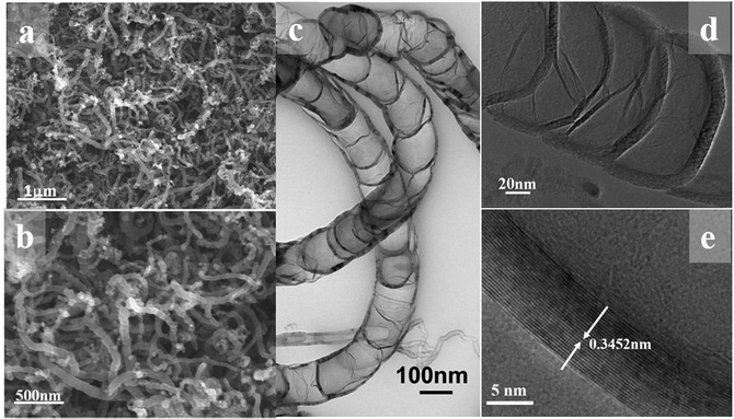
The FESEM image at low magnification in Fig. 1a reveal the one-dimensional feature with high uniformity and length is about several micrometer as shown in Fig. 1b. The bamboo-like structure can be clearly discerned from the TEM observation. As shown in Fig. 1c, the hollow interiors are divided into connected compartments. The hollow compartments in the bamboo-structure tubes are separated at a distance of ca. 50–100 nm by cylinder-shaped graphite layers. The HRTEM image in Fig. 1e reveals that the average interlayer spacing of B-CNTs, both for the tube wall and bamboo knot, is 0.3452 nm, which is in good agreement with the separation of (002) plane of hexagonal graphite. The morphological characterization indicates that the hollow bamboo knots which are closed pores in B-CNTs. These structure are not accessible for N2 in surface area measurement, the BET surface area for B-CNTs only is 22.674 m2 g−1. The nitrogen sorption isotherm and corresponding pore size distribution curve of the B-CNTs are shown in Fig. S2.† The isotherm is type IV curve, characteristic of mesoporous materials.24,25 The unclosed adsorption and desorption branches of the isotherm of B-CNTs at low relative pressure may be related to the swelling effect, or the limited access of nitrogen molecules to the pores.26In order to get an insight into the structure of B-CNTs, X-ray powder diffraction (XRD), Raman spectroscopy and energy dispersive spectroscopy (EDS) measurements were performed. Fig. 2a displays the XRD patterns of B-CNTs. As observed from the patterns, two diffraction peaks at 2θ around 25.8° and 43° can be easily indexed as (002) and (100) plane of the hexagonal phase graphite (JCPDS no. 41-1487), whereas the 2θ = 44.1°, 51.4° and 75.8° can be assigned to (111), (200) and (220) diffraction plane of the face-centered cubic Ni (JCPDS no. 04-0850), which may be derived from the catalysts.27 This result shows that the nickel catalyst, especially the nickel particles encapsulated with carbon layers, remained as nickel particles rather than nickel oxide in the B-CNTs.28,29
Raman scattering has been proved to be an essential tool to characterize carbon materials. As shown in Fig. 2b, two peaks (∼1342 cm−1 and 1571 cm−1) in the wave number range of 1000–2000 cm−1 can be clearly observed, and attributed to the A1g vibration mode of the disordered carbon (D-band) and the E2g vibration mode of the ordered graphitic carbon (G-band), respectively.30 The G-band is stronger than that of the D-band (IG/ID = 1.72), reflects a higher level of graphitization of B-CNTs.31,32 The EDS measurement of B-CNTs shown in Fig. 2c confirms that the B-CNTs are composed of carbon element.
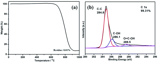
TGA was performed to quantitatively examine the compositional characterization of the B-CNTs (Fig. 3a). As can be seen, 8.01% of the sample is left after 900 °C. That means that the nickel composition is nearly 8.01%, including both nickel catalysts and residual nickel in the B-CNTs structure. The data also shows a good purity of the B-CNTs in the arc process. Moreover, the XPS spectra was carried out to further characterize the internal bonding of the B-CNTs. The C 1s spectra of the B-CNTs ranged from 280 to 296 eV (Fig. 3b) which possessed three peaks at 284.8, 286.1, and 289.5 eV, corresponding to sp2 C groups, hydroxyl groups, and carboxyl groups, respectively.33 The atomic percentage of carbon is calculated to be about 99.31%, suggesting that the surface atomic concentration of non-carbon species is very low. The O 1s and Ni 2p spectra of the B-CNTs is shown in Fig. S3.† The noise level of the low intensity peaks appears to be due to the powder-type samples.29 In view of the above mentioned results, we considered that the most of nickel in the samples existed as nickel nanoparticles encapsulated inside B-CNTs, negligible amount of the nickel was in the state of NiO.
The forming process of coal-derived B-CNTs was discussed in the previous report.21,34,35 The basic units of coal molecular released a large number of aromatic fragments under the arc plasma conditions. These fragments would deposit and dissolve on the surface of catalyst, which might be in liquid, quasi-liquid or solid state under the reaction conditions. And following that, the wall of carbon nanotubes was formed by the fragments' surface diffusion and nucleation process. The constant supply of aromatic fragments would further lead to the propagation of wall. Meanwhile, the growth of carbon nanotube wall prompted the catalyst to move forward, when the moving speed is faster than the speed of generation of carbon nanotube wall, the new compartment would start to grow. The formation of compartments would be repeated if there was a moderate rate of movement between carbon wall and catalyst particle, and the B-CNTs were formed finally.
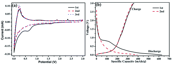
In order to access the benefit of the bamboo-structure CNTs as electrodes, we have studied the electrochemical performance of the B-CNTs for their potential use as anode materials in LIBs. As shown in Fig. 4a, it can be observed from CV curves that the redox peaks of carbon nanotubes are located at 0.25 V for anodic scan, and 0.6 V for cathodic scan. The location of peaks matches well with charge–discharge plot. Moreover, it is remarkable that the CV curves almost overlap after the first cycle, which may be due to the benefit of a stable solid electrolyte interphase SEI film formed on the surfaces and had little effects on the capacities in proceeding cycles. Meanwhile the SEI film can prevent direct contact of the B-CNTs with the electrolyte during subsequent charge–discharge cycles, thus leading to a high coulombic efficiency (≥96%) and the stable and superior reversibility of the sample. Fig. 4b shows the initial and the second charge/discharge voltage profiles of the B-CNTs at a current density of 25 mA g−1. There was a clear discharge plateau at around 0.75 V, indicating that a protective solid surface film was formed on the two electrode surfaces due to the electrolyte being irreversibly reduced.36 The oxidation peak located at about 1.8 V is associated with the partial decomposition of the SEI films, while the main oxidation peak located at ca. 2.3 V is considered to originate from the conversion of Ni into NiO.37,38 For the second cycles, the potential plateau is disappeared which is consistent with the CV results. A high initial discharge capacity of 628.7 mA h g−1 is calculated based on the active material. Despite the irreversible loss of the first cycle, the capacity still remain higher than that of the theoretical value of graphite, owing to the structure feature of B-CNTs.
 | ||
| Fig. 4 (a) The cyclic voltammetry curve, (b) charge/discharge curves in the 1st and 2nd cycle of coal-derived B-CNTs electrode. | ||
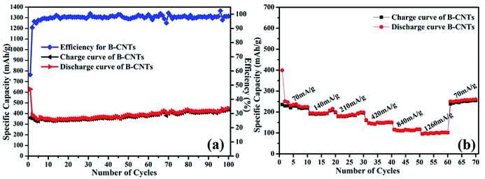
The cyclability of B-CNTs is shown in Fig. 5a. The B-CNTs electrode exhibits a high reversible specific capacity of 450.1 mA h g−1 after 100 cycles. Furthermore, the coulombic efficiency of the B-CNTs rapidly increases from 57.3% for the first cycle to about 96% after five cycles and remains nearly 99% thereafter. For comparison, cycling performance and capacity of carbonaceous anodes reported in previous works are listed in Table 1. It can be clearly seen that the as-prepared B-CNTs show a better cyclability and stability compared to recent reports.6,39–43 The rate capability of Li ion batteries using the B-CNTs anode was also investigated. As shown in Fig. 5b, the charge–discharge rates for the B-CNTs electrodes are substantially increased from 70 mA g−1 to 1260 mA g−1. Remarkably, the discharge specific capacity can be recovered to >250 mA h g−1 when the rate is returned to 70 mA g−1, which is even higher than the specific capacity obtained in the initial 10 cycles. The phenomenon of a gradual capacity increase during cycling is common in many carbonaceous materials.44–46 The Nyquist plots for the B-CNTs in fresh coin cells and a Nyquist plot for the B-CNTs after a CV were tested (see Fig. S4†). The charge transfer resistance is reduced after cyclic voltammetry due to the activation of electrode materials.47
 | ||
| Fig. 5 (a) Cycling performance of B-CNTs electrode at a current density of 25 mA g−1; (b) rate performance of the B-CNTs electrode at different current densities. | ||
| Typical materials | Current density (mA g−1) | First capacity (mA h g−1) | Cycle number | Remaining capacity (mA h g−1) | First coulombic efficiency (%) | Ref. |
|---|---|---|---|---|---|---|
| SWNTs | 50 | 942 | 60 | 150 | — | 39 |
| 3D CNTs | 37.2 | 580 | 4 | 310 | — | 40 |
| Q-CNTs | 20 | 969 | 30 | 321.2 | 40 | 41 |
| MWNTs | 37.2 | 712 | 20 | 210 | 24.1 | 6 |
| Hierarchical porous carbon | 18.6 | 716 | 20 | 273 | 38.8 | 42 |
| 3D honeycomb carbons | 50 | 1021 | 100 | 257 | 28.7 | 43 |
| B-CNTs | 25 | 628.7 | 100 | 450.1 | 53.7 | This work |
The above results demonstrate that the B-CNTs electrode exhibits a better capacity retention and rate capability. These favorable performances may be in favor of the special structure of B-CNTs and the presence of Ni particles in the structure. There are a large number of defects derived from bending graphite sheets in B-CNTs. The exposed edges plane of graphene sheets of B-CNTs is beneficial for efficient Li insertion.48,49 On the other hand, the Ni could greatly reduce the charge-transfer impedance of the electrode as a conductive agent.50
4. Conclusions
In summary, bamboo-structure CNTs were synthesized from coal through an arc discharge process with Ni–Sm2O3 as catalyst. Benefiting from the structural merits of the special shaped CNTs, the B-CNTs exhibited excellent lithium storage performance in terms of high reversible capacity and excellent rate capability when evaluated as an anode material for LIB. Specifically, a high discharge capacity of 450.1 mA h g−1 was observed even after 100 cycles of charge/discharge. This work may inspire new possibilities to cost-effective synthesis of novel structured carbon nanomaterials for energy storage applications.Acknowledgements
This work is supported by the Ten Thousand Back-up Talent Program (wr2015cx01), the Achievement Transformation Project of Xinjiang province (2016C03007), the National Science Foundation of Xinjiang Uygur Autonomous Region of China (No. 2013211B15) and the National Science Foundation of China (No. U1203292).Notes and references
- P. C. Sun, L. Y. Wu, J. W. Gao, G. A. Cheng, G. Chen and R. T. Zheng, Adv. Mater., 2013, 25, 4938–4943 CrossRef CAS PubMed.
- P. M. Ajayan, Chem. Rev., 1999, 99, 1787–1800 CrossRef CAS PubMed.
- R. H. Baughman, A. A. Zakhidow and W. A. Heer, Science, 2002, 297, 787–792 CrossRef CAS PubMed.
- C. Casas and W. Li, J. Power Sources, 2012, 208, 74–85 CrossRef.
- B. J. Landi, M. J. Ganter, C. D. Cress, R. A. DiLeo and R. P. Raffaelle, Energy Environ. Sci., 2009, 2, 638–654 CAS.
- C. Masarapu, V. Subramanian, H. W. Zhu and B. Q. Wei, Adv. Funct. Mater., 2009, 19, 1008–1014 CrossRef CAS.
- W. W. Lei, S. Liu and W. H. Zhang, RSC Adv., 2017, 7, 224–230 RSC.
- L. M. Dai, D. W. Chang, J. B. Baek and W. Lu, Small, 2012, 8, 1130–1166 CrossRef CAS PubMed.
- X. Xu, H. Tan, K. Xi, S. J. Ding, D. M. Yu, S. D. Cheng, G. Yang, X. Y. Peng, A. Fakeeh and R. V. Kumar, Carbon, 2015, 84, 491–499 CrossRef CAS.
- Y. K. Tang, L. Liu, X. C. Wang, H. J. Zhou, D. Z. Jia, W. Xia, Z. B. Zhao and J. S. Qiu, J. Power Sources, 2016, 319, 227–234 CrossRef CAS.
- X. B. Cheng, G. L. Tian, X. F. Liu, J. Q. Nie, M. Q. Zhao, J. Q. Huang, W. C. Zhu, L. Hu, Q. Zhang and F. Wei, Carbon, 2013, 62, 393–404 CrossRef CAS.
- Y. K. Tang, L. Liu, X. C. Wang, H. J. Zhou and D. Z. Jia, RSC Adv., 2014, 4, 44852–44957 RSC.
- S. Bals, K. J. Batenburg, J. Verbeeck, J. Sijbers and G. V. Tendeloo, Nano Lett., 2007, 7, 3669–3674 CrossRef CAS.
- L. Zhang, J. Wang, Y. Gu, G. Zhao, Q. Qian, J. Li, X. Pan and Z. Zhang, Mater. Lett., 2012, 67, 17–20 CrossRef CAS.
- J. H. Won, H. M. Jeong and J. K. Kang, Adv. Energy Mater., 2017, 7, 1601355 CrossRef.
- K. Xu, Y. Li, F. Yang, W. Yang, L. Zhang, C. Xu, T. Kaneko and R. Hatakeyama, Carbon, 2014, 68, 511–519 CrossRef CAS.
- C. Schwandt, A. T. Dimitrov and D. J. Fray, Carbon, 2012, 50, 1311–1315 CrossRef CAS.
- Y. Wang, L. Liu, M. Li, S. Xu and F. Gao, Biosens. Bioelectron., 2011, 30, 107–111 CrossRef CAS PubMed.
- N. Li, Y. F. Ma, B. Wang, Y. Huang, Y. P. Wu, X. Yang and Y. S. Chen, Carbon, 2011, 49, 5132–5141 CrossRef CAS.
- D. S. Su, The use of natural materials in nanocarbon synthesis, ChemSusChem, 2009, 2, 1009–1020 CrossRef CAS PubMed.
- Y. F. Li, J. S. Qiu, Z. B. Zhao, T. H. Wang, Y. P. Wang and W. Li, Chem. Phys. Lett., 2002, 366, 544–550 CrossRef CAS.
- J. S. Qiu, Z. Y. Wang, Z. B. Zhao and T. H. Wang, Fuel, 2007, 86, 282–286 CrossRef CAS.
- J. S. Qiu, Y. F. Li, Y. P. Wang, T. H. Wang, Z. B. Zhao, Y. Zhou, F. Li and H. M. Cheng, Carbon, 2003, 41, 2170–2173 CrossRef CAS.
- K. X. Wang, M. D. Wei, M. A. Morris, H. S. Zhou and J. D. Holmes, Adv. Mater., 2007, 19, 3016–3020 CrossRef CAS.
- W. Li, D. H. Chen, F. Xia, J. Z. Y. Tan, P. P. Huang, W. G. Song, N. M. Nursam and R. A. Caruso, Environ. Sci.: Nano, 2016, 3, 94–106 RSC.
- M. Rose, W. Bohlmann, M. Sabo and S. Kaskel, Chem. Commun., 2008, 21, 2462–2464 RSC.
- D. W. Wang, F. Li, G. Q. Lu and H. M. Cheng, Carbon, 2008, 46, 1593–1599 CrossRef CAS.
- C. T. Wirth, S. Hofmann and J. Robertson, Diamond Relat. Mater., 2009, 18, 940–945 CrossRef CAS.
- S. H. Bae, K. Karthikeyan, Y. S. Lee and I. K. Oh, Carbon, 2013, 64, 527–536 CrossRef CAS.
- F. B. Su, C. K. Poh, J. S. Chen, G. W. Xu, D. Wang, Q. Li, J. Y. Lin and X. W. Lou, Energy Environ. Sci., 2011, 4, 717–724 CAS.
- L. S. Zhang, W. Li, Z. M. Cui and W. G. Song, J. Phys. Chem. C, 2009, 113, 20594–20598 CAS.
- W. Li, L. S. Zhang, Q. Wang, Y. Yu, Z. Chen, C. Yan Cao and W. G. Song, J. Mater. Chem., 2012, 22, 15342–15347 RSC.
- S. W. Lee, B. M. Gallant, Y. Lee, N. Yoshida, D. Y. Kim, Y. Yamada, S. Noda, A. Yamada and Y. Shao-Horn, Energy Environ. Sci., 2012, 5, 5437–5444 CAS.
- X. Wu, L. X. Wang and D. Z. Jia, Chin. J. Inorg. Chem., 2013, 29, 1842–1848 Search PubMed.
- M. Lim, J. P. Y. Tan, C. Boothroyd, K. P. Loh, E. S. Tok and Y. L. Foo, Nano Lett., 2007, 7, 2234–2238 CrossRef PubMed.
- M. Chen, C. Yu, S. Liu, X. Fan, C. Zhao, X. Zhang and J. Qiu, Nanoscale, 2015, 7, 1791–1795 RSC.
- X. H. Huang, J. P. Tu, X. H. Xia, X. L. Wang and J. Y. Xiang, Electrochem. Commun., 2008, 10, 1288–1290 CrossRef CAS.
- Y. Xia, W. K. Zhang, Z. Xiao, H. Huang, H. J. Zeng, X. R. Chen, F. Chen, Y. P. Gan and X. Y. Tao, J. Mater. Chem., 2012, 22, 9209–9215 RSC.
- J. X. Li, Y. Zhao and L. H. Guan, Electrochem. Commun., 2010, 12, 592–595 CrossRef CAS.
- C. Kang, I. Lahiri, R. Baskaran, W. G. Kim, Y. K. Sun and W. Choi, J. Power Sources, 2012, 219, 364–370 CrossRef CAS.
- J. H. Zhou, H. H. Song, B. C. Fu, B. Wu and X. H. Chen, J. Mater. Chem., 2010, 20, 2794–2800 RSC.
- J. Yi, X. P. Li, S. J. Hu, W. S. Li, L. Zhou, M. Q. Xu, J. F. Lei and L. S. Hao, J. Power Sources, 2011, 196, 6670–6675 CrossRef CAS.
- H. B. Li, W. J. Kang, Y. Yu, J. F. Liu and Y. T. Qian, Carbon, 2012, 50, 4787–4793 CrossRef CAS.
- Z. Chen, Y. Yan, S. Xin, W. Li, J. Qu, Y. G. Guo and W. G. Song, J. Mater. Chem. A, 2013, 1, 11404–11409 CAS.
- X. D. Li, Y. Feng, M. C. Li, W. Li, H. Wei and D. D. Song, Adv. Funct. Mater., 2015, 25, 6858–6866 CrossRef CAS.
- L. Qie, W. M. Chen and Z. H. Wang, et al., Adv. Mater., 2012, 24, 2047–2050 CrossRef PubMed.
- X. F. Sun, Y. L. Xu, P. Ding, G. G. Chen, X. Y. Zheng, R. Zhang and L. Li, J. Power Sources, 2014, 255, 163–169 CrossRef CAS.
- L. Zou, R. T. Lv, F. Y. Kang, L. Gan and W. C. Shen, J. Power Sources, 2008, 184, 566–569 CrossRef CAS.
- X. F. Li, J. Liu, Y. Zhang, Y. L. Li, H. Liu, X. B. Meng, J. L. Yang, D. S. Geng, D. N. Wang, R. Y. Li and X. L. Sun, J. Power Sources, 2012, 197, 238–245 CrossRef CAS.
- S. S. Niu, Z. Y. Wang, T. Zhou, M. L. Yu, M. Z. Yu and J. S. Qiu, Adv. Funct. Mater., 2017, 27, 1605332 CrossRef.
Footnote |
| † Electronic supplementary information (ESI) available. See DOI: 10.1039/c7ra04047d |
| This journal is © The Royal Society of Chemistry 2017 |


