 Open Access Article
Creative Commons Attribution 3.0 Unported Licence
Sandwich-structured rGO/PVDF/PU multilayer coatings for anti-corrosion application
Yuan-Kai Xiaoa,
Wei-Fu Jib,
Kuei-Sen Changc,
Kuei-Ting Hsud,
Jui-Ming Yehb and
Wei-Ren Liu *a
*a
aDepartment of Chemical Engineering at Chung Yuan Christian University (CYCU), Chung Li 32023, Taiwan, Republic of China. E-mail: WRLiu1203@gmail.com
bDepartment of Chemistry at CYCU, Chung Li 32023, Taiwan, Republic of China
cRefining and Manufacturing Research Institute at CPC Corporation, Chiayi City 60051, Taiwan, Republic of China
dDepartment of Chemical Engineering, Army Academy, Taoyuan City 32092, Taiwan, Republic of China
First published on 5th July 2017
Abstract
In this study, we fabricated a novel sandwich structure by combining reduced graphene oxide (rGO), polyvinylidene difluoride (PVDF) and polyurethanes (PU) to construct a composite film for anti-corrosion applications. The corrosion performances of the rGO/PVDF/PU multi-layered coatings on carbon steel were evaluated in 30 wt% boiling sulfuric acid solution for 1 h and 3.5 wt% NaCl electrolyte for electrochemical tests. The results show that the addition of PU and rGO dramatically improves the anti-corrosion performance of the bare PVDF coating and the optimized content of rGO is 7 wt%. The anticorrosion performances of corrosion potential, corrosion current and protection efficiency after protection coating are measured to be −757 mV, 0.1 μA cm−2 and 99%, respectively. The excellent results obtained could be explained by barrier effects, where the hydrophobic property and high-aspect-ratio of rGO in the PVDF matrix inhibit corrosion factors from diffusing into the substrate.
1. Introduction
Corrosion protection is very important technology in the metallic finishing industry. Corrosion is a very costly problem, which has a major impact on the economies of industrial nations. However, corrosion cannot be fully inhibited. Thus, corrosion control strategies focus on slowing the kinetics and/or altering its mechanism. Nowadays, there are different strategies for corrosion protection, including cathodic protection,1,2 protective coatings,3–5 corrosion inhibitors6,7 and other.8–10 Recently, graphene has emerged as a promising building block in polymer matrices on account of its unique geometry and novel physical properties, such as high specific surface area, superior mechanical strength, high aspect ratio, electrical mobility, thermal conductivity and barrier properties.11–18 As reported in the literature, graphene has great application potential in the corrosion protection field. Additionally, there is increasing research interest in related materials, such as GO and rGO.19 GO is the exfoliated product of graphite oxide, which is prepared via a modified Hummers method from graphite power.20 Subsequently, GO can be transformed into rGO via chemical,21,22 thermal,23,24 or electrochemical reduction.25 However, one major challenge in the preparation of graphene is its irreversible agglomeration and restacking as a result of strong van der Waals interaction and the out-of-plane π bond between the individual graphene nanosheets. On the other hand, after the oxidation reaction, oxygen-containing functional groups such as epoxy, hydroxyl, carboxyl and carbonyl groups are located either on the basal plane or on the edge of the single atom thin sheet. The presence of these functional groups causes the GO sheets to be strongly hydrophilic, which allows GO to swell and disperse in various polar solvents readily.26 Chang et al. reported that graphene provides more desirable anti-corrosion properties for polyaniline than clay due to its higher aspect ratio.27 They reported that the well-dispersed graphene displayed remarkable anti-corrosion properties because of enhanced barrier properties.28 Unfortunately, the presence of strong intrinsic van der Waals attraction between the fillers and the absence of bonding between graphene and the polymer matrix pose a substantial obstacle to obtain graphene-based composites with excellent dispersion and compatibility. To a great extent, this impairs the anti-corrosion performance of graphene-based composites. Meanwhile, nanocomposites synthesized containing graphene-based materials such as graphene nanoplates (GNPs), graphene nanosheets (GNSs) and GO display excellent beneficial properties when employed in diverse applications.29–35 Research associated with conductive graphene, which has a relatively high aspect ratio of ∼500, has attracted much interest.36 The lower density and higher aspect ratio of conductive graphene compared with that of non-conductive clay platelets triggered its potential application as an advanced gas barrier polymer nanocomposite.27 Mo et al. reported that functionalized graphene (FG) and functionalized graphene oxide (FGO) were obtained by treating graphene and GO with 3-aminopropyltriethoxysilane (APTES).37 Then, they fabricated a series of PU-based composite coatings reinforced with well dispersed FG and different surface texture densities in the PU matrix which displayed anti-corrosion properties. Singh et al. proved that GO polymer composite coatings are an effective protective shield against the oxidation and corrosion of metal.38 Zhang et al. reported a PVDF/GO solution via a simple blending method.25 The oxygen containing groups in GO platelets allow them to be dispersed in PVDF solution homogeneously and prevent agglomeration, and the GO can be translated to RGO via thermal reduction during the hot-molding process. The enhanced absorption and dielectric property of PVDF/rGO composites were also investigated. Karan et al. demonstrated that the Fe–rGO/PVDF nanocomposite exhibits superior piezoelectric energy harvesting and ferroelectric properties, where a higher proportion of the polar piezoelectric γ-phase of PVDF is achieved by simply using the solvent casting method, which exclusively produced an output voltage of 5.1 V and short circuit current of 0.254 μA without the application of electrical poling.41In our previous studies, we demonstrated that the corrosion protection properties of nano-graphene/epoxy composites coated on metal surfaces are capable of enhancing the corrosion protection of pure metals effectively.39,40 In this study, we further fabricate anticorrosive rGO/PVDF/PU coatings which provide two-fold protection against metal corrosion. In the first step of the protection mechanism, the hydrophobic graphene is proven to display excellent corrosion protection capability. Second, the well-dispersed reduced graphene nanosheets in the PVDF matrix increase the tortuosity of the diffusion pathway of H2O and O2 molecules. The detailed anticorrosion performance of the GPN coated on cold-rolled steel (CRS) is evaluated through a series of electrochemical corrosion measurements in a corrosive medium.
2. Experimental
2.1. Sample preparation
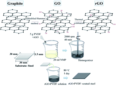
Polyvinylidene difluoride (Kureha, KF9200), N-methyl-2-pyrrolidone (Alfa), sodium nitrate (J. T. Baker), potassium permanganate (SHOWA) and hydrogen peroxide (J. T. Baker) were used as received. Aqueous sulfuric acid and hydrochloric acid were purchased from Echo Chemical Co. Ltd. Graphene nanosheets (SFG44-GNS) prepared from SFG44 synthetic graphite powder (TIMCAL®) were used. The detailed experimental conditions are reported in our previous work.20 The obtained graphene oxide powder was subjected to thermal exfoliation at 1050 °C in air for 30 s. This procedure resulted in few-layer reduced graphene nanosheets. The GNSs were characterized via SEM, X-ray diffraction, Raman spectroscopy, and TEM. A series of rGO/PVDF nanocomposite coatings with 0 wt%, 1 wt% and 7 wt% GNSs in PVDF (denoted as GPN, GPN1 and GPN7, respectively) were fabricated as follows: first, 4 g PVDF was dissolved in 20 g NMP. Then 0.043 g rGO was mixed using a homogenizer for 40 min at room temperature. After mixing, drops of the mixture solution were spread on a stainless steel plate followed by the dipping coating process. Finally, cured GPN membranes were obtained with a thickness of ca. 120 μm at 60 °C overnight in a vacuum oven. Graphene/PVDF nanocomposite coatings with different mass fractions of reduced GNSs were prepared in the same way. The fabrication of the GPNs is illustrated schematically in Fig. 1. The whole process of three-layer coating is described as follow: the PU coating was used as the first coating layer on a steel substrate via the dipping coating method. After drying at ambient temperature for one day, the second layer, PVDF, was spread on the as-prepared substrate by dipping coating. Then it was placed in an oven at 60 °C overnight. Finally, the substrate was coated with the rGO/PVDF nanocomposite in the same way as the previous step. Thus, the multilayer protecting structure of RGO/PVDF/PU was obtained on the steel substrate.2.2. Electrochemical corrosion studies
Electrochemical corrosion measurement was performed on a VoltaLab 50. All electrochemical corrosion measurements were performed in a double-wall jacketed cell covered with a glass plate, in which water was maintained at a constant operational temperature of 25 ± 0.5 °C. The open-circuit potential (OCP) at the equilibrium state of the system was recorded as the corrosion potential (Ecorr in mV versus the saturated calomel electrode (SCE)). Tafel plots were obtained by scanning the potential from −500 to 500 mV above Ecorr at a scan rate of 10 mV min−1. The corrosion current (Icorr) was determined by superimposing a straight line along the linear portion of the cathodic or anodic curve and extrapolating it through Ecorr. The corrosion rate (Rcorr, in milli-inches per year, MPY) was calculated using eqn (1):| Ecorr (MPY) = [0.13Icorr (E.W.)]/[A × d] | (1) |
3. Results and discussion
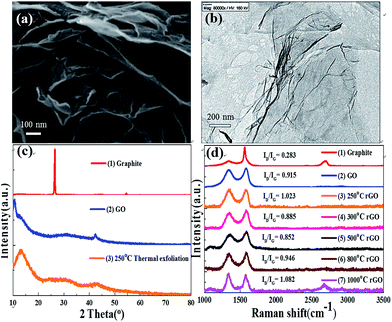
The SEM image in Fig. 2(a) shows that the synthesized rGO are flexible flakes with a rough morphology and thickness in the nanoscale. The thickness of the rGO after thermal treatment was smaller than that of the GO flakes. The decrease in thickness of the rGO nanosheets is due to several factors, including the removal of oxygen-containing functional groups by heating and elimination of the interlamellar water present in graphite oxide which depends on the relative humidity. The TEM images reveal that the synthesized rGO is transparent and very flexible (Fig. 2(b)). Furthermore, there were some folds in the flexible sheets, which indicate that the rGO was very thin. Since all the synthesized materials are nanostructured, embedding them in the PVDF matrix as fillers is likely to enhance the anticorrosion performance of PVDF. Due to the presence of fillers in the coating matrix, rGO serves as a barrier, which enhances the coating impermeability by increasing the tortuosity of the diffusion pathway of molecules in the coating (physical barrier effect). Generally, fillers with a high aspect ratio and large filler-matrix interfacial area are beneficial for increasing the tortuosity of the diffusion pathway.27 The flake-like GPNs are excellent anti-corrosion fillers due to the following reasons. On one hand, the aspect ratio of GPNs is high because the lateral dimension of GPNs is micron-sized.42The XRD patterns of the graphite, GO and rGO are shown in Fig. 2(c). As shown in Fig. 2(c-2), GO has an intense crystalline peak at 10.5°, which corresponds to a d-spacing of 8.42 Å. The interlayer spacing of the GO sheets is attributed to the oxygenated functional groups introduced by the modified Hummers method. The XRD pattern of rGO is shown in Fig. 2(c-3), in which the peak of GO is weakened. The rGO peak at 13.4° corresponds to the d-spacing of 6.6 Å, which is less than that of GO due to the emission of oxygen-containing functional groups.43 The results of the d-spacing demonstrate that the reduction was successful. Raman spectroscopy was implemented to characterize the structure of the synthesized materials. Fig. 2(d) shows the Raman spectra of graphite, GO and rGO. rGO displays a D band at 1350 cm−1 corresponding to the vibration of graphene defects or edges and a G band at 1598 cm−1 which is assigned to the in-phase vibration of the graphite lattice.
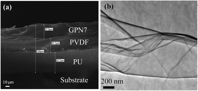
Cross-section SEM was performed to observe the structure of the multiple anti-corrosion layers. Fig. 3(a) shows that there were good connections between the layers and the substrate. The pure PU layer presented in Fig. 3(a) exhibits a smooth and uniform fracture surface without obvious defects, which could also be a great attachment to non-organic steel substrates. On the other hand, when a small amount of rGO was added into the PVDF matrix, a rougher surface and some cracks appeared which were initiated by the interfacial interaction between rGO and the PVDF matrix. Moreover, the PVDF in the middle of the structure acted a thermal buffer layer, reduced to determine graphene dispersed situation in the PVDF matrix and enabled to descript the degree of exfoliation. Fig. 3(b) shows the TEM micrograph of the PVDF composite of graphene with the graphene content of 7 wt%. The gray region of the photograph represents the domain of PVDF matrix and the black lines correspond to the cross section of graphene nanosheets. This indicates that the attachment of carboxylic groups onto the graphene surface effectively enhances the compatibility between reduced-graphene nanosheets and the polymer matrix, which leads to improved dispersion. In addition, the number of graphene layers is less than 10 and the folds appear. The reduced-graphene nanosheets could be described as few-layer graphene.
Graphene is a flat monolayer of carbon atoms tightly packed into a two-dimensional (2D) honeycomb lattice. However, during the reduction process, graphene oxide can easily aggregate into graphite again. In order to prevent this for occurring, we had to optimize the contents of the co-doped polymer slurry. GPN blended with different contents (0, 3, 5, 7, 10 and 13 wt%) of reduced-graphene oxide was boiled in sulfuric acid for 1 h. We measured the weight difference in grams of the samples and the 0 wt% sample and defined the weight difference per unit area (m2) as the weight loss. Fig. 4 shows that the best anti-corrosion performance was observed for GPN7. If the concentration was less than 7 wt%, the amount of graphene was not strong enough to defend the corrosive medium. Sulfuric acid molecules diffuse into the depth of the substrate to destroy the steel easily. On the contrary, when the concentration was over 7 wt%, the probability of aggregation between graphene layers increases. To avoid the aggregation in the slurry, we selected a good dispersion agent for graphene, NMP. NMP is not only a powerful solvent for dispersing SWCNTs,44,45 graphene,46 and GO,47 but also a solvent to dissolve PVDF polymer. In addition, we used the sonication method for 30 min and the assistance of a homogenizer to overcome the aggregation problem. The greater anti-corrosion performance evident in GPN7 was also further analyzed. The inset in Fig. 4 displays the SEM image of the composition optimized rGO/PVDF/PU sample after acid corrosion tests. Compare to the fresh coating shown in Fig. 3(a), the structure of GPN7 changed from a dense structure to a porous structure. In comparison, the PVDF and PU layers remained dense even after heavy corrosion tests in 30 wt% boiling sulfuric acid solution for 1 h. The results confirm that the three-layer sandwich structure of rGO/PVDF/PU efficiently protects the substrate from acid corrosion.
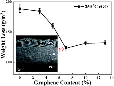 | ||
| Fig. 4 Mass loss of composite membranes with different contents of rGO, PVDF and rGO–PVDF. Inset: SEM image of the sample after the corrosion tests. | ||
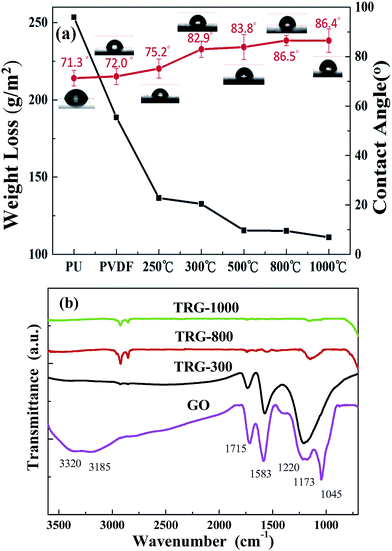
It is generally believed that a higher contact angle value denotes a more hydrophobic surface.48 The above results indicate that the surface hydrophobic property depends on the presence of the functionalized groups containing carbon–oxygen bonds in graphene. The enhancement of the hydrophobic property prevents the absorption of water through the coatings. Fig. 5(a) shows the change in the water contact angle with the addition of rGO at different reduction temperatures under Ar. As the reduction temperature increases, the more functionalized groups containing oxygen vaporize into CO2, which causes the graphene to become hydrophobic and enhances the blocking capacity of the coating. The contact angle of a water droplet on the sample surface was increased from ∼72° for the PVDF surface to ∼86.4° for GPN7s by tuning the reduction temperature of graphene. The water repellent ability of the GPN coatings is a very important parameter, which was simultaneously determined during the sulfuric test. The result indicates that the weight loss decreased from 188.7 to 115.2 g m−2 which improved the anti-corrosion efficiency by about 39%. The higher reduction temperature resulted in a better hydrophobic phenomenon. Fig. 5(b) shows FITR spectra of GO under different reduction temperatures. Obviously, with an increase in reduction temperature from 300 °C, 800 °C to 1000 °C, the corresponding oxygen-containing functional groups decreased. Thus, the surface properties of the GPN layer could be easily tuned by the reduction temperature.
Fig. 6(a) shows the PU, PVDF and GPN7 composite coatings, where the left three samples displayed resistance to the sulfuric acid. According to the test, although GPN7 had the best anti-corrosion performance, there were some defects on the edges of the steel substrates. The GPN7 membrane peeled off from the substrate because of the weak interaction. On the other hand, the PU coating was still intact and in good shape as determined from is physical properties. There were no obvious cracks on its surface structure, but its chemical stability was not as good as GPN7. On the basis of the corrosion test, we combined the advantages of PU and GPN7 and built a new structure of two layers with the same thickness. Fig. 6(a) demonstrates that by using the structured technique, the anti-corrosion performance improved evidently. In order to overcome the high temperature system, the structure must endure thermal expansion tension. We integrated the three membranes and built composite sandwich structures to determine the optimization permutation, and the results are shown in Fig. 6(b). We used two types of additives, GO and rGO as obstacles in the PVDF matrix. It is obviously seen that there were good blocking effects when the GPN7 membrane was on the outside. Moreover, it also had a good performance because the PU polymer played the role of a primer. From the physical properties of the sandwich structures we successfully determined the optimal sandwich structure.
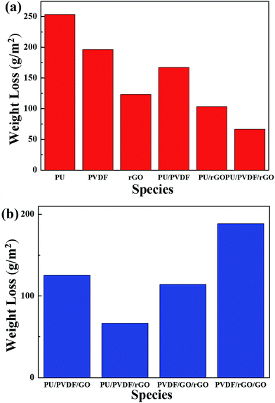 | ||
| Fig. 6 (a) Anti-corrosion properties of each composite membrane and the structured layers and (b) anti-corrosion properties of the sandwich structure layers by arrangement. | ||
On the basis of a series of electrochemical measurements (i.e., corrosion potential, polarization resistance, and corrosion current measured in a corrosive medium) we concluded that the GPN7 coating is superior at protecting the CRS electrode against corrosion than the common PU and PVDF coatings. The Tafel polarization curves of the bare substrate, pure PVDF, GPN1 and GPN7 composite coatings exposed to 3.5 wt% NaCl solution are displayed in Fig. 7. Information about the corrosion current can be obtained by extrapolating the Tafel plots from both the cathodic and anodic polarization curves for the respective corrosion processes.49,50 Extrapolating the cathodic and anodic polarization curves to their point of intersection provides both the corrosion potential (Ecorr) and the corrosion current (Icorr). In general, a lower Icorr value represents a lower corrosion dynamic rate. Corrosion protection studies were performed on samples with 10 ± 1 μm thick coatings that were immersed in a corrosive medium for 40 min. The protection efficiency (η) of the coatings on the substrate was calculated from the Icorr values according to eqn (2):51
 | (2) |
 and Icorr are the corrosion current densities of the bare and coated substrate, respectively. The Tafel plots for the sample-coated CRS electrode gave a corrosion potential of Ecorr = −883, −803 and −757 mV for the PVDF, GPN1 and GPN7 coatings, respectively, which was more positive than that for the bare CRS electrode, where Ecorr = −924 mV. Moreover, the corrosion current of the PVDF, GPN1-coated and GPN7-coated CRS electrodes was ca. 12.62, 0.32 and 0.10 μA cm−2, respectively, which was significantly lower than that of the bare CRS electrode (147.91 μA cm−2). The corresponding Icorr decreased considerably when we used the GPN-coated bare CRS electrode with the additive of reduced graphene oxide to produce hydrophobic properties. Moreover, the corrosion potential of the GPN7-coated CRS electrode was more positive than that of the GPN1-coated CRS electrode, as Ecorr increased from −803 to −757 mV (vs. SCE). These electrochemical measurement results show that the GPN7 coating provided better protection against corrosion for the CRS electrode than the other coatings.
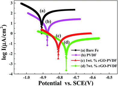 | ||
| Fig. 7 Tafel plots for (a) bare steel, (b) PVDF-coated, (c) 1 wt% rGO–PVDF coated and (d) 7 wt% rGO–PVDF coated CRS electrodes measured in 3.5 wt% NaCl aqueous solution. | ||
Dielectric spectroscopy, which is also known as impedance spectroscopy or electrochemical impedance spectroscopy (EIS), is used to measure the dielectric properties of a medium and express them as a function of frequency.52,53 EIS was also used to examine the difference in the activity between the surface of the bare CRS electrode and the PVDF- or GPN-coated electrodes. Impedance is a complex resistance when alternate current flows through a circuit consisting of capacitors or a combination of circuits.54 EIS measurements result in currents over a wide range of frequencies. Complex nonlinear least-squares procedures available in numerous EIS-data-fitting computer programs could be used to fit the model to the experimental data in order to obtain the Randles circuit parameters. For the simulation studies, the corrosion of the metal was modeled using an equivalent circuit (called a Randles circuit), as illustrated in Fig. 9, which consists of a double-layer capacitor connected in parallel with a charge-transfer resistor and in series with an electrolyte solution resistor. The impedance (Z) depends on the charge-transfer resistance (Rct), the solution resistance (Rs), the capacitance of the electrical double layer, and the frequency of the AC signal (ω) as follows:
 | (3) |
The fitted data fit well to all the experimental electrochemical data. The high-frequency intercept is equal to the solution resistance and the low-frequency intercept is equal to the sum of the solution and charge transfer resistances.55 In general, a larger semicircle diameter (charge transfer resistance) represents a lower corrosion rate. Fig. 8 shows the Nyquist plots of the four measured samples. The first sample (a) is uncoated CRS. The series of samples denoted as (b), (c) and (d) represent CRS coated by PVDF, GPN1 and GPN7, respectively. The charge transfer resistances of all the samples, as determined by subtracting the intersection of the high-frequency end from the low-frequency end of the semicircle arc with the real axis, are 710.2, 898.5, 1105 and 1453 Ω cm2, respectively. The EIS Bode plots (impedance vs. frequency) of all the samples are shown in Fig. 9. Zreal is a measure of corrosion resistance.56 A low Zreal value could be caused by very high capacitance and/or very low resistance of the coating.57,58 Also, the capacitance value is related to the extent to which water penetrates the coating.59
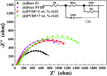 | ||
| Fig. 8 Nyquist plots of (a) bare steel, (b) PVDF-coated, (c) 1 wt% rGO–PVDF coated, and (d) 7 wt% rGO–PVDF coated CRS electrodes (■ experimental data and—fitted data). | ||
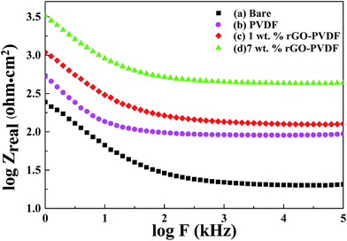 | ||
| Fig. 9 Bode plots for (a) bare, (b) PVDF-coated, (c) 1 wt% rGO–PVDF coated, and (d) 7 wt% rGO–PVDF coated CRS electrodes. | ||
In the case of the Bode plots, the value of Zreal at the lowest frequency also represents the corrosion resistance. The Bode magnitude plots for the uncoated CRS and CRS coated by PVDF, GPN1 and GPN7 show Zreal values of 20.37, 94.19, 127.35, and 434.51 Ω cm2, respectively, at the low frequency region. These results clearly demonstrate that the GPN7 coating protects the CRS electrode against corrosion better than the PVDF and GPN1 coatings. The increase in impedance for the GPN7-coated electrode can be attributed to the hydrophobicity and barrier effects of GNSs dispersed in the composites of the coating. The hydrophobicity of GPN7 compared to that of PVDF and GPN1 may result from the low wettability and dispersed graphene in the PVDF matrix which increase the tortuosity of the corrosive media diffusion pathway (lower diffusion length), as shown in Fig. 10.60–63
 | ||
| Fig. 10 Schematic representation of the hydrophobic surface and oxygen following a tortuous path through PVDF and RPC materials. | ||
Table 1 lists the Ecorr, Icorr, thickness and protection efficiency (PEF%) reported in previous work. The protection efficiency was utilized to evaluate the anticorrosive performance of the coatings using eqn (4).
 | (4) |
| Sample | Ecorra (mV) | Icorr (μA cm−2) | Protection efficiency (PEF%) | Thickness (μm) | Reference |
|---|---|---|---|---|---|
| a Saturated calomel electrode was employed as the reference electrode. | |||||
| 7 wt% rGO–PVDF | −757 | 0.1 | 99.9% | 120 | This work |
| EPGN1 | −432 | 0.15 | 98.9% | 20 | 28 |
| PTC-11 | −502 | 0.26 | 97.8% | 10 | 64 |
| PAGCs | −537 | 0.38 | 97.4% | 29 | 27 |
| PEI/G1 | −10.7 | 0.15 | 99.1% | 65 | 65 |
| 5 wt% RGO/PANI | −714 | 12.14 | 79.3% | 50 | 66 |
In order to well understand the mechanism of anticorrosion for the rGO–PVDF coatings, the results are attributed to the barrier effects of the materials. Well dispersed graphene layer materials were incorporated into the PVDF coating (i.e. GPN1 and GPN7) which increased the diffusion pathways for reactive chemicals (H2SO41 and Cl−) which contributed to a significant enhancement in the corrosion protection of the metallic substrate compared with that of neat PVDF coating. Moreover, GPN7 has a better anticorrosive performance than that of GPN1, with increase in the amount of graphene from 1 wt% to 7 wt%. This excellent result is attributed to fact that a higher content of graphene added into the polymer coating could provide longer diffusion pathways and promote the enhancement of the corrosion protection of the metallic substrate compared with that of the GPN1 coating, as shown in Fig. 10.
4. Conclusions
In this study, we successfully converted graphite into exfoliated-GO via a modified Hummer's method. After thermal reduction by treating the exfoliated-GO with Ar, the reduced graphene nanosheets displayed an improved hydrophobic property to prevent corrosion. As an effective building block, the graphene additive comprehensively enhanced the anti-corrosion properties of the PVDF composite coating due to the obstructive and barrier properties it provided. Also, the optimized additive content was 7 wt%. As the content of rGO was further increased in excess of the optimized additive amount, the anti-corrosion performance of the PVDF composite coatings was weakened. This is because it contributed to a growing number of aggregates across the whole PVDF composite coating and shortened the diffusion path. Finally, we successfully presented a novel PU/PVDF/rGO composite and the sandwich structure demonstrates excellent anti-corrosion effects for metal protection due to its strong mechanical properties.Acknowledgements
This research was financially supported by the Ministry of Science and Technology (MOST 105-2622-E-033-003-CC2 and MOST 104-2628-E-033-002-MY3).Notes and references
- G. Shen, Y. Chen and C. Lin, Thin Solid Films, 2005, 489, 130–136 CrossRef CAS.
- H. Yun, J. Li, H. B. Chen and C. J. Lin, Electrochim. Acta, 2007, 52, 6679–6685 CrossRef CAS.
- B. Wessling, Adv. Mater., 1994, 6, 226–228 CrossRef CAS.
- P. A. Kilmartin, L. Trier and G. A. Wright, Synth. Met., 2002, 131, 99–109 CrossRef CAS.
- A. F. Frau, R. B. Pernites and R. C. Advincula, Ind. Eng. Chem. Res., 2010, 49, 9789–9797 CrossRef CAS.
- M. Quraishi and J. Rawat, Mater. Chem. Phys., 2002, 73, 118–122 CrossRef CAS.
- T. Söylev and M. Richardson, Constr. Build. Mater., 2008, 22, 609–622 CrossRef.
- K. Kendig, M. Hon and L. Warren, Prog. Org. Coat., 2003, 47, 183–189 CrossRef.
- A. Kumar, L. Stephenson and J. Murray, Prog. Org. Coat., 2006, 55, 244–253 CrossRef CAS.
- C. Suryanarayana, K. C. Rao and D. Kumar, Prog. Org. Coat., 2008, 63, 72–78 CrossRef CAS.
- M. J. Allen, V. C. Tung and R. B. Kaner, Chem. Rev., 2009, 110, 132–145 CrossRef PubMed.
- D. R. Dreyer, R. S. Ruoff and C. W. Bielawski, Angew. Chem., Int. Ed., 2010, 49, 9336–9344 CrossRef CAS PubMed.
- A. K. Geim and K. S. Novoselov, Nat. Mater., 2007, 6, 183–191 CrossRef CAS PubMed.
- K. P. Loh, Q. Bao, P. K. Ang and J. Yang, J. Mater. Chem., 2010, 20, 2277–2289 RSC.
- C. N. R. Rao, A. K. Sood, K. S. Subrahmanyam and A. Govindaraj, Angew. Chem., Int. Ed., 2009, 48, 7752–7777 CrossRef CAS PubMed.
- W. Ma, L. Wu, D. Zhang and S. Wang, Colloid Polym. Sci., 2013, 291, 2765–2773 CAS.
- H. He and C. Gao, ACS Appl. Mater. Interfaces, 2010, 2, 3201–3210 CAS.
- H. J. Song and N. Li, Appl. Phys. A:, 2011, 105, 827–832 CrossRef CAS.
- D. Fan, C. Zhang, J. He, R. Hua, Y. Zhang and Y. Yang, J. Mater. Chem., 2012, 22, 18564–18571 RSC.
- W. S. Hummers and R. E. Offeman, J. Am. Chem. Soc., 1958, 80, 1339 CrossRef CAS.
- D. R. Dreyer, S. Park, C. W. Bielawski and R. S. Ruoff, Chem. Soc. Rev., 2010, 39, 228–240 RSC.
- H. Bai, C. Li and G. Shi, Adv. Mater., 2011, 23, 1089–1115 CrossRef CAS PubMed.
- R. Larciprete, S. Fabris, T. Sun, P. Lacovig, A. Baraldi and S. Lizzit, J. Am. Chem. Soc., 2011, 133, 17315–17321 CrossRef CAS PubMed.
- Y. Xu, Q. Wu, Y. Sun, H. Bai and G. Shi, ACS Nano, 2010, 4, 7358–7362 CrossRef CAS PubMed.
- X. J. Zhang, G. S. Wang, W. Q. Cao, Y. Z. Wei, M. S. Cao and L. Guo, RSC Adv., 2014, 4, 19594–19601 RSC.
- S. Stankovich, D. A. Dikin, G. H. Dommett, K. M. Kohlhaas, E. J. Zimney, E. A. Stach, S. Stankovich, D. A. Dikin, G. H. Dommett, K. M. Kohlhaas, E. J. Zimney and E. A. Stach, Nature, 2006, 442, 282–286 CrossRef CAS PubMed.
- C. H. Chang, T. C. Huang, C. W. Peng, T. C. Yeh, H. I. Lu, W. I. Hung, C. J. Weng, T. I. Yang and J. M. Yeh, Carbon, 2012, 50, 5044–5051 CrossRef CAS.
- K. Chang, C. Hsu, H. Lu, W. Ji, C. Chang and W. Li, et al., eXPRESS Polym. Lett., 2014, 8, 243–255 CrossRef.
- C. Bao, L. Song, C. A. Wilkie, B. Yuan, Y. Guo and Y. Hu, et al., J. Mater. Chem., 2012, 22, 16399–16406 RSC.
- J. R. Potts, O. Shankar, L. Du and R. S. Ruoff, Macromolecules, 2012, 45, 6045–6055 CrossRef CAS.
- X. Jiang and L. T. Drzal, J. Power Sources, 2012, 218, 297–306 CrossRef CAS.
- M. Li, X. Huang, C. Wu, H. Xu, P. Jiang and T. Tanaka, J. Mater. Chem., 2012, 22, 23477–23484 RSC.
- B. K. Kim, M. W. Jang, H. C. Park, H. M. Jeong and E. Y. Kim, J. Polym. Sci., Part A: Polym. Chem., 2012, 50, 1418–1423 CrossRef CAS.
- S. R. Prabakar, Y. H. Hwang, E. G. Bae, D. K. Lee and M. Pyo, Carbon, 2013, 52, 128–136 CrossRef.
- S. R. Prabakar, Y. H. Hwang, B. Lee, K. S. Sohn and M. Pyo, J. Electrochem. Soc., 2013, 160, A832–A837 CrossRef CAS.
- Z. Xu and M. J. Buehler, ACS Nano, 2010, 4, 3869–3876 CrossRef CAS PubMed.
- M. Mo, W. Zhao, Z. Chen, Q. Yu, Z. Zeng and X. Wu, et al., RSC Adv., 2015, 5, 56486–56497 RSC.
- B. P. Singh, B. K. Jena, S. Bhattacharjee and L. Besra, Surf. Coat. Technol., 2013, 232, 475–481 CrossRef CAS.
- Z. Yu, H. Di, Y. Ma, Y. He, L. Liang and L. Lv, et al., Surf. Coat. Technol., 2015, 276, 471–478 CrossRef CAS.
- Z. Yu, H. Di, Y. Ma, L. Lv, Y. Pan and C. Zhang, et al., Appl. Surf. Sci., 2015, 351, 986–996 CrossRef CAS.
- S. K. Karan, D. Mandal and B. B. Khatua, Nanoscale, 2015, 7, 10655–10666 RSC.
- H. Wang, Q. Hao, X. Yang, L. Lu and X. Wang, Nanoscale, 2010, 2, 2164–2170 RSC.
- Q. Shao, J. Tang, Y. Lin, J. Li, F. Qin and J. Yuan, et al., J. Power Sources, 2015, 278, 751–759 CrossRef CAS.
- C. Furtado, U. Kim, H. Gutierrez, L. Pan, E. Dickey and P. C. Eklund, J. Am. Chem. Soc., 2004, 126, 6095–6105 CrossRef CAS PubMed.
- S. Giordani, S. D. Bergin, V. Nicolosi, S. Lebedkin, M. M. Kappes and W. J. Blau, et al., J. Phys. Chem. B, 2006, 110, 15708–15718 CrossRef CAS PubMed.
- Y. Hernandez, V. Nicolosi, M. Lotya, F. M. Blighe, Z. Sun and S. De, et al., Nat. Nanotechnol., 2008, 3, 563–568 CrossRef CAS PubMed.
- J. Paredes, S. Villar-Rodil, A. Martinez-Alonso and J. Tascon, Langmuir, 2008, 24, 10560–10564 CrossRef CAS PubMed.
- C. Zhou, X. Lu, Z. Xin, J. Liu and Y. Zhang, Prog. Org. Coat., 2013, 76, 1178–1183 CrossRef CAS.
- A. Mitra, Z. Wang, T. Cao, H. Wang, L. Huang and Y. Yan, J. Electrochem. Soc., 2002, 149, B472–B478 CrossRef CAS.
- D. E. Beving, A. M. McDonnell, W. Yang and Y. Yan, J. Electrochem. Soc., 2006, 153, B325–B329 CrossRef CAS.
- S. Banerjee, A. Mishra, M. M. Singh, B. Maiti, B. Ray and P. Maiti, RSC Adv., 2011, 1, 199–210 RSC.
- Y. D. Liu, F. F. Fang and H. J. Choi, Langmuir, 2010, 26, 12849–12854 CrossRef CAS PubMed.
- Y. D. Liu, B. J. Park, Y. H. Kim and H. J. Choi, J. Mater. Chem., 2011, 21, 17396–17402 RSC.
- S. M. Park and J. S. Yoo, Anal. Chem., 2003, 75, A455–A461 Search PubMed.
- A. Amirudin and D. Thieny, Prog. Org. Coat., 1995, 26, 1–28 CrossRef CAS.
- F. Zucchi, V. Grassi, A. Frignani, C. Monticelli and G. Trabanelli, J. Appl. Electrochem., 2006, 36, 195–204 CrossRef CAS.
- M. B. Kannan, D. Gomes, W. Dietzel and V. Abetz, Surf. Coat. Technol., 2008, 202, 4598–4601 CrossRef CAS.
- A. S. Hamdy, E. El-Shenawy and T. El-Bitar, Int. J. Electrochem. Sci., 2006, 1, 171–180 CAS.
- G. Reinhard, P. Simon and U. Rammelt, Prog. Org. Coat., 1992, 20, 383–392 CrossRef CAS.
- I. H. Tseng, Y. F. Liao, J. C. Chiang and M. H. Tsai, Mater. Chem. Phys., 2012, 136, 247–253 CrossRef CAS.
- J. R. Potts, D. R. Dreyer, C. W. Bielawski and R. S. Ruoff, Polymer, 2011, 52, 5–25 CrossRef CAS.
- S. Morimune, T. Nishino and T. Goto, ACS Appl. Mater. Interfaces, 2012, 4, 3596–3601 CAS.
- P. Podsiadlo, A. K. Kaushik, E. M. Arruda, A. M. Waas, B. S. Shim and J. Xu, et al., Science, 2007, 318, 80–83 CrossRef CAS PubMed.
- K. C. Chang, W. F. Ji, C. W. Li, C. H. Chang, T. L. Chuang, J. M. Yeh and W. R. Liu, eXPRESS Polym. Lett., 2014, 8(12), 908–919 CrossRef.
- H. Alhumade, A. Abdala, A. Yu, A. Elkamel and L. Simon, Can. J. Chem. Eng., 2016, 94(5), 896–904 CrossRef CAS.
- K. Cai, S. Zuo, S. Luo, C. Yao, W. Liu, J. Ma, H. Mao and Z. Li, RSC Adv., 2016, 6, 95965–95972 RSC.
| This journal is © The Royal Society of Chemistry 2017 |

