 Open Access Article
Creative Commons Attribution 3.0 Unported Licence
Enhanced charge collection and stability in planar perovskite solar cells based on a cobalt(III)-complex additive†
Yunping Ma‡
a,
Jiandong Fan‡ab,
Cuiling Zhanga,
Hongliang Lia,
Wenzhe Li *b and
Yaohua Mai*ab
aInstitute of Photovoltaics, College of Physics Science and Technology, Hebei University, Baoding, 071002, China. E-mail: yaohuamai@jnu.edu.cn
bInstitute of New Energy Technology, College of Information Science and Technology, Jinan University, Guangzhou, 510632, China. E-mail: li_wz16@jnu.edu.cn
First published on 1st August 2017
Abstract
Chemical doping has emerged as a favourable method for tuning the electrical properties of the hole-transport layer (HTL) in perovskite solar cells. Herein, we demonstrated an efficient dopant, cobalt(III) complex tris[2-((1H-pyrazol-1-yl)-4-tert-butylpyridine)cobalt(III)tris(bis(trifluoromethylsulfonyl)imide)] (FK209), which exhibited concentration distribution characteristics. The interfacial charge collection is demonstrated to be enhanced. We obtained the optimal power conversion efficiency (PCE) of 17.34% by optimizing the Co-complex doping ratio. Moreover, we found that the doping of Co-complex into the HTL significantly improved the stability under a sensitive atmosphere.
Introduction
Perovskite solar cells (PSCs) have been considered to be promising materials due to their ever-increasing power conversion efficiencies, easy manufacture via low temperature processes, and extremely low costs.1–4 To achieve high efficiencies, in addition to a high quality perovskite film, an electron-transport layer (ETL) with high electron mobility and a hole-transport layer (HTL) with high hole mobility are required. 2,2′,7,7′-Tetrakis (N,N-di-p-methoxyphenylamine) 9,9′-spirobifluorene (spiro-OMeTAD) is commonly used as an efficient hole transport material.5–7 Spiro-OMeTAD suffers from both low conductivity and hole mobility in its pristine form, which directly decreases the efficiency.8–11Chemical doping is one of the most useful methods to generate additional charge carriers, which allows for an increase in the charge transport capacity and enhances the conductivity.12 The chemical dopant N(PhBr)3SbCl6 was first introduced to oxidize spiro-OMeTAD, but was rapidly replaced by a more effective additive, lithium bis(trifluoromethanesulfonyl)imide (Li-TFSI).13 Li-TFSI can facilitate the oxidation of spiro-OMeTAD by oxygen in air, which thereby allows an increase in the number of charge carriers in spiro-OMeTAD.14 However, it is difficult to control the amount of the oxidized spiro-OMeTAD and obtain consistent results, which is dependent on various factors including the concentrations of Li+ ions and oxygen gas exposure.15 To solve this problem, a series of dopants such as cobalt complexes FK209,16 and FK102;17 copper salts, CuSCN and CuI;18 silver salt Ag-TFSI;19 and tin salt SnCl4 were carefully studied.20 Among these dopants, Co-complex (FK209) is considered to be a good candidate to improve both the efficiency and reproducibility of the PSCs.21,22 Some studies have focussed on Co-complex (FK209) as an oxidant working on spiro-OMeTAD. However, only a few studies have been reported on its concentration distribution in the film and its interfacial function in devices.
In this study, we investigated the concentration distribution and interfacial functions of Co-complex as a dopant in spiro-OMeTAD. The study shows the effect of the Co-complex dopant on the charge collection and charge transport properties for the perovskite/HTL interface. The charge collection rate and charge recombination were also investigated via PL and EIS measurement. Based on the dopant, the overall device performance was enhanced, with the PCE as high as 17.34% and excellent stability under a sensitive atmosphere.
Experimental
Materials
CH3NH3I was synthesized by an ice-bath solution-processed approach. Typically, 5 mL hydroiodic acid (57 wt% in water, Aldrich) was dropwise added to 25 mL ethanol in a 100 mL beaker. After stirring the mixed solution for 10 min, 6 mL CH3NH2 (33% in ethanol, Aldrich) was added to the obtained solution until the solution turned light yellow. The solution was then stirred for 30 min at room temperature with an aim of obtaining a uniform precursor. After this, the solution was poured into a dish from the beaker and then heated at 100 °C for 2 h to obtain white powders.Solar cell fabrication
Fluorine tin oxide (FTO)-coated glass with a sheet resistance of 14 Ω sq−1 was washed with deionized water, acetone, ethanol, and isopropanol for 10 min under sonication and then treated with oxygen plasma for 5 min. A compact layer of TiO2 was deposited on the FTO substrate by spin-coating a titanium precursor (350 μL titanium(IV) isopropoxide (99.99%, Aldrich)) in a mixed solvent of 2.5 mL ethanol and 2 M HCl in 2.5 mL ethanol at 2000 rpm for 60 s followed by calcination in an hot plate at 500 °C for 30 min. Subsequently, the TiO2-coated FTO substrates were transferred to a nitrogen-filled glovebox and pre-heated at 120 °C for 15 min.The synthesized MAI (0.477 g) was mixed with PbCl2 (0.278 g) in anhydrous N,N-dimethylformamide (1.392 mL) (DMF, 99.8%, Aldrich) under stirring at room temperature for about 30 min to produce a clear CH3NH3PbI3−xClx precursor solution with the concentration of 35 wt%. This prepared solution (100 μL) was then deposited on the cleaned FTO substrate by spin-coating at 2000 rpm for 45 s. The obtained CH3NH3PbI3−xClx film was then annealed at 90 °C for 160 min and then heated to 120 °C for 17 min in a glove box.
The HTL solution was prepared by dissolving 300 mg spiro-OMeTAD (99.5%, Xi'an polymer Light Technology Corp) in 2.91 mL chlorobenzene (99.8%, Aldrich) and then adding the Co-complex (99%, Dyenamo) stock solution (180 mg mL−1 in acetonitrile). In addition, 29 μL tBP (96%, Aldrich) and 126 μL Li-TSFI (98%, Aldrich) stock solution (170 mg mL−1 in acetonitrile) were added as additives. For comparison, the same concentrations of spiro-OMeTAD solution-doped Li-TSFI and tBP were also prepared. The HTM solution was prepared by spin-coating at 3000 rpm for 45 s, and then, the cell was completed by thermally evaporating a 120 nm thick silver layer.
Characterizations
Time-of-flight secondary ion mass spectrometry (ToF-SIMS) measurement was used to profile organic materials for elemental analysis with Ar cluster ions or C60 ions. Impedance spectroscopy measurement was performed using an impedance analyzer (Zahner PP211). Different bias potentials ranging from 0.5 V to 0.9 V were applied to each cell under dark conditions. A voltage perturbation with 10 mV of amplitude was applied at the frequencies between 100 kHz and 0.1 Hz. The measurement results were fitted with the software Z-View. Conductivity measurement of the FTO/HTL/Ag hole only devices was conducted under ambient conditions using a sourcemeter (Agilent B1500A) in a two-point contact setup. Moreover, 400 nm thick different HTLs were deposited by spin-coating on a glass substrate, and then, a 100 nm-thick silver layer was deposited by thermal evaporation through a shadow mask (channel length: 2 mm; channel width: 20 mm). Current–voltage (J–V) characteristics of the perovskite solar cells were measured using a semiconductor device analyzer (Keithley 2601B) and a SAN-EI solar simulator (XES-100S1) with an AM 1.5 G spectrum. The light intensity on the sample was adjusted to 1000 W m−2 using a standard Si cell (RS-ID-4). The scan rate was fixed to 0.15 V s−1. A black mask with an aperture (9 mm2) was placed on the top of the device to control the effective electrode area. PL spectra were obtained by time correlated single photon counting using FLS 920 (Edinburgh Instruments). The experiment was performed with an excitation laser wavelength of 470 nm and monitored at 780 nm emission. Field-emission scanning electron microscopy (SEM) was used to characterize the morphology of the obtained thin film. Both top-down and cross-sectional views were obtained using FEI NovaNanoSEM450. The crystal structure was characterized by a Bruker D8 Advance X-ray diffractometer (XRD) with Cu Kα radiation at 40 kV and 40 mA.Results and discussion
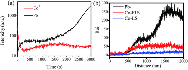
We fabricated the Co-complex and Li-TFSI doped spiro-OMeTAD layer on the perovskite film. The thickness of the spiro-OMeTAD layer is about 400 nm, which is shown in Fig. S1.† The target film was measured by time-of-flight secondary ion mass spectrometry (ToF-SIMS) (Fig. 1). The positions of different layers through the depth profile of the entire device were estimated via detection of the dominant secondary-ion signal for various layers. Note that the concentration of Co+ is higher at 2000–3000 s, and Pb− is growing during the same time period. Because the Co dopant concentration is just 4 mol% in spiro-OMeTAD, the amplitude of the Co-curve is much smaller than that of the Pb-curve. The results indicate that the Co-complex is enriched at the interface between the perovskite and HTL. To further identify this result, we also conducted energy dispersive spectrometer (EDS) measurement, as shown in Fig. 1b. The result is consistent with the ToF-SIMS result.The dopant concentrated at the interface is supposed to influence the charge collection properties. Thus, we have investigated the transfer kinetic process of charge carriers from perovskite to HTL with and without the Co-complex dopant, which have been marked as FLS and LS, respectively. The photoluminescence (PL) measurement was carried out on the glass/perovskite/HTL films. Fig. 2a shows the steady-state PL spectra. We found that the characteristic emission peak of CH3NH3PbI3−xClx was at ∼774 nm, which was in accordance with previous reports.23,24 In the case of the FLS sample, the PL intensity is quenched by nearly 40%, thus demonstrating a more effective charge transport in comparison with that in the FK209 doped HTL.25 Further, time-resolved PL decay curves are shown in Fig. 2b. The faster quenching and shorter lifetime of the excited state are shown and they indicate the shortened rate for charge transfer at the interface between the perovskite and FLS HTL.
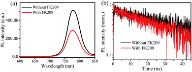 | ||
| Fig. 2 (a) Steady-state photoluminescence spectra of the perovskite thin films with the HTL doped with and without Co-complex dopant and (b) the time-resolved photoluminescence spectra of the HTL. | ||
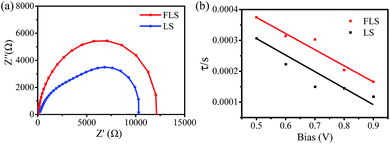
We fabricated the full solar cell devices. The cross-sectional image of the typical devices with a structure of FTO/compacted-TiO2/CH3NH3PbI3−xClx/HTL/Ag is shown in Fig. S1.† The top-down view and XRD patterns of the perovskite film are shown in Fig. S2,† which indicate that the obtained film is homogeneous and has high coverage.26,27 Based on the well-fabricated devices, we investigated the interface performance including the charge transport, recombination, and accumulation for perovskite solar cells by electrical impedance spectroscopy (EIS) measurement.28–31 The Nyquist plots of the devices in Fig. 3a were acquired in the frequency range from 1 Hz to 100 kHz in weak light and under different biases. We have used a two-lumped RC circuit in a series to fit the impedance data, which was generally used in the literature.32,33 The arcs in the high frequency region are mainly attributed to the charge contact resistance through the interface of the c-TiO2/CH3NH3PbI3−xClx/spiro-OMeTAD contact,31,33 with two typical impedance elements of charge contact resistance (Rcon) and geometrical capacitance (C). The arc in the middle frequency region corresponds to the charge recombination process at the compact-TiO2/perovskite or perovskite/HTL interface, where the interfacial recombination resistance (Rrec) and chemical capacitance (Cμ) can be extracted. In addition, the charge recombination lifetime τ (τ = RrecCμ) in the middle frequency region was determined, as shown in Fig. 3b. The device with a Co-complex-dopant exhibited a longer recombination lifetime than the device without the Co-complex-dopant. Thus, the Co-complex doped into HTL significantly improves the charge transport and reduces the charge recombination.
The enhancement of the interfacial properties is supposed to be attributed to the presence of the Co-complex at the interface. Then, we measured the conductivity of the HTL films with different Co-complex concentrations. The conductivities are carefully compared in Fig. 4a and b. The conductivity of pristine spiro-OMeTAD is 3.8 × 10⁻⁸ S cm−1, which is similar to the previous report.34 Surprisingly, with the increasing doping concentration, the curve shows a maximum conductivity of 4.6 × 10⁻⁵ S cm−1, which increases by three orders of magnitude than that of the film without a Co-complex dopant. This result indicates that the doping of the Co-complex into spiro-OMeTAD improves the intrinsic conductivity as the concentration increases to 8 mol%. The dramatic enhancement of the conductivity with the Co-complex dopant is associated with the presence of more holes during the oxidization process of spiro-OMeTAD.
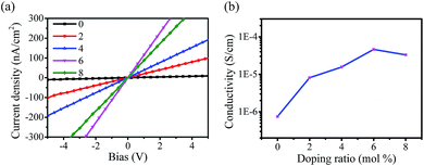 | ||
| Fig. 4 (a) Linear I–V curves for different doping concentrations of the Co-complex and (b) the corresponding conductivity for different doping concentrations of the Co-complex. | ||
We further optimized the power conversion efficiency (PCE) of the PSC devices via controlling the concentration of the Co-complex dopant. The parametric statistical results are shown in Fig. S3a.† The results show that the optimized concentration is 4 mol%. Interestingly, the variation trend of PCE is different from the conductivity evolution with the dopant concentration, which would be associated to the concentration increase at the interface. As shown in Table 1, the open circuit voltage (VOC) and short circuit current density (JSC) were clearly improved when the Co-complex was doped, leading to a substantial improvement in the average PCE from 13.8% to 16.8%. The statistical data of PCEs are obtained from 30 devices of different batches. Fig. 5 shows the J–V curves of the champion cell. The device without the Co-complex dopant showed a comparably low efficiency of 14.59% with a JSC of 21.12 mA cm−2, an VOC of 0.93 V, and a FF of 0.74. Impressively, when the doped concentration of the Co-complex dopant was 4 mol%, the efficiency reached 17.34% with a JSC of 22 mA cm−2, a VOC of 1.02 V, and a FF of 0.77. Although hysteresis still exists, there is an obvious reduction with the Co-complex dopant from 0.37 to 0.26. This may be due to the faster charge transport and fewer defects after Co-complex modified the interface between perovskite and spiro-OMeTAD.35 We observed that the rather higher conversion efficiency of the device with the Co-complex dopant can be ascribed to its higher VOC, JSC, and FF. These results can be attributed to the lower Fermi level with the Co-complex dopant,36 as shown in Fig. S4,† higher conductivity of the HTL at the interface, and faster charge collection. The JSC data acquired from the J–V curve is consistent with the integrated current density of 22 mA cm−2 obtained from the monochromatic incident photon-to-electron conversion efficiency (IPCE) shown in Fig. S3b.†
| Device | Scanning direction | VOC (V) | JSC (mA cm−2) | FF (%) | PCE (%) |
|---|---|---|---|---|---|
| LS | Forward | 0.75 ± 0.05 | 21.0 ± 0.5 | 0.51 ± 0.06 | 8.5 ± 0.7 |
| Reverse | 0.91 ± 0.03 | 20.9 ± 0.4 | 0.72 ± 0.04 | 13.8 ± 1.0 | |
| FLS | Forward | 0.85 ± 0.05 | 21.6 ± 0.5 | 0.63 ± 0.04 | 11.7 ± 1.0 |
| Reverse | 1.01 ± 0.03 | 21.8 ± 0.4 | 0.76 ± 0.02 | 16.8 ± 1.1 |
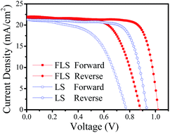 | ||
| Fig. 5 J–V curves obtained under optimized conditions with and without the Co-complex dopant measured under simulated AM 1.5 sunlight of 100 mW cm−2 irradiance. | ||
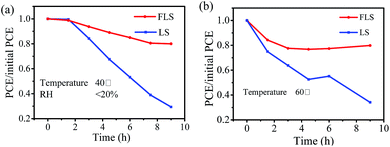
Finally, we investigated the device stability. Fig. 6a shows the light stability under 1 sun AM1.5G illumination in the packing bag at a temperature of 40 °C for 9 hours. The device without the Co-complex dopant shows a poor stability upon light soaking, which retains only about 30% of the initial performance within 9 hours. Conversely, the device with the Co-complex-dopant was much more stable, with a good retention of 80%. Fig. 6b shows the thermal stability under a nitrogen atmosphere at 60 °C and humidity less than 20%. Similarly, the PCE decreased to nearly 30% in 9 hours. With the Co-complex dopant, the PCE was maintained above 80%. We also measured the stability under a humid air atmosphere, as shown in Fig. S5,† and a comparatively good stability was observed. The Co-complex on the perovskite and HTL interface suppresses traps, such that there is less degradation of the device with the Co-complex dopant, which may contribute to the enhancement of interfacial polarity compatibility.
Conclusions
In this study, we employed a Co-complex as a dopant in the spiro-OMeTAD hole transport material. The dopant concentration was shown to be higher in the HTL and perovskite interface, which could thereby enhance the charge carrier collection and transfer. With the extraordinary merits of the modified HTL, we have effectively improved the solar cell efficiency as high as 17.34%, and remarkable device stability has been achieved. Moreover, using of effective chemical doping to tune the charge collection and transport properties is a straightforward method for organic semiconductors, which can be a promising route to fabricate highly efficient and stable PSCs.Acknowledgements
The research was funded by the National Natural Science Foundation of China (No. 51672111), Advanced Talents Program of Hebei Province (No. GCC2014013), Top Young Outstanding Innovative Talents Program of Hebei Province (No. BJ2014009), Natural Science Foundation of Hebei Province (No. F2015201189), and J. Fan thanks for the support of “100 Talents Program of Hebei Province” (E2014100008).References
- M. M. Lee, J. Teuscher, T. Miyasaka, T. N. Murakami and H. J. Snaith, Science, 2012, 338, 643–647 CrossRef CAS PubMed.
- H. S. Jung and N. Park, Small, 2015, 11, 10–25 CrossRef CAS PubMed.
- G. E. Eperon, V. M. Burlakov, P. Docampo, A. Goriely and H. J. Snaith, Adv. Funct. Mater., 2014, 24, 151–157 CrossRef CAS.
- G. C. Xing, N. Mathews, S. Y. Sun, S. S. Lim, Y. M. Lam, M. Gratzel, S. Mhaisalkar and T. C. Sum, Science, 2013, 342, 344–347 CrossRef CAS PubMed.
- S. Kazim, M. K. Nazeeruddin, M. Gratzel and S. Ahmad, Angew. Chem., Int. Ed., 2014, 53, 2812–2824 CrossRef CAS PubMed.
- J. Salbeck, F. Weissörtel and J. Bauer, Macromol. Symp., 1998, 125, 121–132 CrossRef CAS.
- I. Chung, B. Lee, J. He, R. P. H. Chang and M. G. Kanatzidis, Nature, 2012, 485, 486–489 CrossRef CAS PubMed.
- L. Yang, B. Xu, D. Q. Bi, H. N. Tian, G. Boschloo, L. C. Sun, A. Hagfeldt and E. M. J. Johansson, J. Am. Chem. Soc., 2013, 135, 7378–7385 CrossRef CAS PubMed.
- T. Leijtens, I. K. Ding, T. Giovenzana, J. T. Bloking, M. D. McGehee and A. Sellinger, ACS Nano, 2012, 6, 1455–1462 CrossRef CAS PubMed.
- F. Fabregat-Santiago, J. Bisquert, E. Palomares, S. A. Haque and J. R. Durrant, J. Appl. Phys., 2006, 100, 034510 CrossRef.
- R. Schölin, M. H. Karlsson, S. K. Eriksson, H. Siegbahn, E. M. J. Johansson and H. Rensmo, J. Phys. Chem. C, 2012, 116, 26300–26305 Search PubMed.
- H. Xi, X. H. Ma, J. J. Chang, D. Z. Chen, Z. H. Lin, P. Zhong, H. Wang and C. F. Zhang, ACS Omega, 2017, 2, 326–336 CrossRef CAS.
- U. Bach, D. Lupo, P. Comte, J. Moser, F. Weissörtel, J. Salbeck, H. Spreitzer and M. Gratzel, Nature, 1998, 395, 583–585 CrossRef CAS.
- S. Wang, W. Yuan and Y. S. Meng, ACS Appl. Mater. Interfaces, 2015, 7, 24791–24798 CAS.
- A. Abate, T. Leijtens, S. Pathak, J. Teuscher, R. Avolio, M. E. Errico, J. Kirkpatrik, J. M. Ball, P. Docampo, I. McPherson and H. J. Snaith, Phys. Chem. Chem. Phys., 2013, 15, 2572–2579 RSC.
- J. Burschka, F. Kessler, M. K. Nazeeruddin and M. Graetzel, Chem. Mater., 2013, 25, 2986–2990 CrossRef CAS.
- J. Burschka, A. Dualeh, F. Kessler, E. Baranoff, N.-L. CeveyHa, C. Yi, M. K. Nazeeruddin and M. Gratzel, J. Am. Chem. Soc., 2011, 133, 18042–18045 CrossRef CAS PubMed.
- M. Li, Z. K. Wang, Y. G. Yang, Y. Hu, S. L. Feng, J. M. Wang, X. Y. Gao and L. S. Liao, Adv. Energy Mater., 2016, 6, 1601156 CrossRef.
- P. Wang, J. Zhang, Z. B. Zeng, R. J. Chen, X. K. Huang, L. M. Wang, J. Xu, Z. Y. Hu and Y. J. Zhu, J. Mater. Chem. C, 2016, 4, 9003–9008 RSC.
- M. Xu, Y. Rong, Z. Ku, A. Mei, X. Li and H. Han, J. Phys. Chem. C, 2013, 117, 22492–22496 CAS.
- D. Q. Bi, W. G. Tress, M. I. Dar, P. Gao, J. S. Luo, C. Renevier, K. Schenk, A. Abate, F. Giordano, J. C. Baena, J. Decoppet, S. M. Zakeeruddin, M. K. Nazeeruddin, M. Gratzel and A. Hagfeldt, Sci. Adv., 2016, 2, 1501170 Search PubMed.
- K. T. Cho, S. Paek, G. Grancini, C. Roldán-Carmona, P. Gao, Y. Lee and M. K. Nazeeruddin, Energy Environ. Sci., 2017, 10, 621–627 CAS.
- W. Z. Li, W. Zhang, S. V. Reenen, R. J. Sutton, J. D. Fan, A. A. Haghighirad, M. B. Johnston, L. D. Wang and H. J. Snaith, Energy Environ. Sci., 2016, 9, 490–498 CAS.
- N. K. Noel, A. Abate, S. D. Stranks, E. Parrott, V. Burlakov, A. Goriely and H. J. Snaith, ACS Nano, 2014, 8, 9815–9821 CrossRef CAS PubMed.
- Y. Wang, R. Fullon, M. Acerce, C. E. Petoukhoff, J. Yang, C. G. Chen, S. N. Du, S. K. Lai, S. P. Lau, D. Voiry, D. O'Carroll, G. Gupta, A. D. Mohite, S. D. Zhang, H. Zhou and M. Chhowalla, Adv. Mater., 2017, 29, 1603995 CrossRef PubMed.
- W. Z. Li, J. D. Fan, Y. H. Mai and L. D. Wang, Adv. Energy Mater., 2016, 1601433 Search PubMed.
- Y. L. Li, W. H. Sun, W. B. Yan, S. Y. Ye, H. T. Peng, Z. W. Liu, Z. Q. Bian and C. H. Huang, Adv. Funct. Mater., 2015, 25, 4867–4873 CrossRef CAS.
- H. S. Kim, I. Mora-Sero, V. Gonzalez-Pedro, F. FabregatSantiago, E. J. Juarez-Perez, N. G. Park and J. Bisquert, Nat. Commun., 2013, 4, 2242 Search PubMed.
- A. Dualeh, T. Moehl, N. Tetreault, J. Teuscher, P. Gao, M. K. Nazeeruddin and M. Gratzel, ACS Nano, 2014, 8, 362–373 CrossRef CAS PubMed.
- V. Gonzalez-Pedro, E. J. Juarez-Perez, W. S. Arsyad, E. M. Barea, F. Fabregat-Santiago, I. Mora-Sero and J. Bisquert, Nano Lett., 2014, 14, 888–893 CrossRef CAS PubMed.
- E. J. Juarez-Perez, M. Wuβler, F. Fabregat-Santiago, K. LakusWollny, E. Mankel, T. Mayer, W. Jaegermann and I. Mora-Sero, J. Phys. Chem. Lett., 2014, 5, 680–685 CrossRef CAS PubMed.
- A. Pockett, G. E. Eperon, T. Peltola, H. J. Snaith, A. Walker, L. M. Peter and P. J. Cameron, J. Phys. Chem. C, 2015, 119, 3456–3465 CAS.
- W. W. Wang, J. Y. Yuan, G. Z. Shi, X. X. Zhu, S. H. Shi, Z. K. Liu, L. Han, H. Q. Wang and W. L. Ma, ACS Appl. Mater. Interfaces, 2015, 7, 3994–3999 CAS.
- B. Xu, J. Huang, H. Agren, L. Kloo, A. Hagfeldt and L. C. Sun, ChemSusChem, 2014, 7, 3252–3256 CrossRef CAS PubMed.
- J. H. Heo, D. H. Song, H. J. Han, S. Y. Kim, J. H. Kim, D. Kim, H. W. Shin, T. K. Ahn, C. Wolf, T. W. Lee and S. H. Im, Adv. Mater., 2015, 27, 3424–3430 CrossRef CAS PubMed.
- J. Noh, N. J. Jeon, Y. C. Choi, M. K. Nazeeruddin, M. Gratzel and S. I. Seok, J. Mater. Chem. A, 2013, 1, 11842–11847 CAS.
Footnotes |
| † Electronic supplementary information (ESI) available: SEM figures of materials and devices, the statistical IV results. See DOI: 10.1039/c7ra05741e |
| ‡ Yunping Ma and Jiandong Fan contributed equal to this work. |
| This journal is © The Royal Society of Chemistry 2017 |

