 Open Access Article
Creative Commons Attribution 3.0 Unported Licence
Soluble fluorene–benzothiadiazole polymer-grafted graphene for photovoltaic devices†
Junying Hea,
Feng Bao *a,
Shuang Yana,
Fangqing Wenga,
Rui Ma*b,
Yanping Liua and
Hao Dinga
aDepartment of Chemistry, Central China Normal University, Wuhan 430079, China. E-mail: macrobf@gmail.com; Tel: +86-27-63233058
bEngineering Research Center of Nano-Geomaterials of Ministry of Education, China University of Geosciences, Wuhan 430074, China. E-mail: marui.cug@gmail.com; Tel: +86-013971315390
First published on 19th July 2017
Abstract
Herein, a polymer based on fluorene and benzothiadiazole (PFBT) was covalently grafted on brominated graphene (G-PFBT) sheets via Suzuki coupling reaction and characterized by Fourier transform infrared (FTIR), ultraviolet-visible (UV-vis), fluorescence emission (FL), and 1H-NMR spectroscopy. The obtained composite shows good solubility in organic solvents such as THF, DMF, and toluene, which is beneficial for the solution casting of device fabrication. In addition, photoinduced charge transfer was observed between the conjugated polymer donor and graphene acceptor, which was also an advantage of using G-PFBT in solar cells. The open-circuit voltage, short-circuit current density, and fill factor of a photovoltaic device based on G-PFBT are 0.22 V, 1.42 mA cm−2, and 0.26, respectively.
1. Introduction
During the past decade, organic polymer solar cells that offer great potential for environmentally friendly and low-cost manufacturing methods on a large area, light, and flexible substrate have attracted significant attention.1–3 These advantages have led to the achievement of effective efficiencies in organic solar cells although they are still far below those of the inorganic devices based on Si.4 Great progress has been made since the improvement of components in the active layer, the device structure, and fabricating techniques, and the performance of organic solar cells has recently increased dramatically, reaching a power conversion efficiency as high as 10% under an AM1.5G (AM1/4 air mass) simulated solar illumination.5 These record efficiency structures are based on a donor–acceptor system between photoactive materials.6 There is electron transfer from the donor phase to the acceptor phase.7 A major obstacle in the field of donor–acceptor-based systems for photovoltaic applications is the development of novel donor and acceptor polymer or materials to increase the open circuit voltage (Voc) or the short circuit current (Jsc).8A well-known carbon material, graphene, is a single layer of carbon atoms forming a two-dimensional sp2-hybridized sheet, with a large theoretical specific surface area (2630 m2 g−1),9 thermal conductivity (∼5000 W m−1 K−1),10 high Young's modulus (∼1.0 TPa),11 high intrinsic mobility (200![[thin space (1/6-em)]](https://www.rsc.org/images/entities/char_2009.gif) 000 cm2 V−1 s−1),12 optical transmittance (∼97.7%), and good electrical conductivity; it merits attention for applications such as in transparent conductive electrodes, among many other potential applications. Owing to these unique electronic and optical properties, graphene has attracted significant attention from both experimental and theoretical communities in recent years;13,14 moreover, it has been successfully applied in organic photovoltaic devices as an electron acceptor material because of its fundamental electronic properties and semimetallic nature. However, how to improve the solubility and apply its electronic properties in the solid state continue to be the key problem areas. To overcome the abovementioned obstacles, covalent chemical functionalization is a feasible way.15 By introducing organic molecule chains such as P3HT,16 P3OT,17 poly-fluorene,18 etc., not only it becomes soluble in common organic solvents, but also thin films can be obtained from graphene derivatives; moreover, these films have been used as photoactive materials in organic solar cells due to their high conductivity, excellent transparency, and high chemical and thermal stabilities.19
000 cm2 V−1 s−1),12 optical transmittance (∼97.7%), and good electrical conductivity; it merits attention for applications such as in transparent conductive electrodes, among many other potential applications. Owing to these unique electronic and optical properties, graphene has attracted significant attention from both experimental and theoretical communities in recent years;13,14 moreover, it has been successfully applied in organic photovoltaic devices as an electron acceptor material because of its fundamental electronic properties and semimetallic nature. However, how to improve the solubility and apply its electronic properties in the solid state continue to be the key problem areas. To overcome the abovementioned obstacles, covalent chemical functionalization is a feasible way.15 By introducing organic molecule chains such as P3HT,16 P3OT,17 poly-fluorene,18 etc., not only it becomes soluble in common organic solvents, but also thin films can be obtained from graphene derivatives; moreover, these films have been used as photoactive materials in organic solar cells due to their high conductivity, excellent transparency, and high chemical and thermal stabilities.19
In our previous studies, small organic molecules, such as hexylbenzene, thiophene, poly(9,9-dihexylfluorene), and polythiophene, were grafted onto brominated graphene, and a series of conjugated molecule-grafted graphene with good solubility and tunable optical properties was obtained.20,21 Herein, 9,9-dihexylfluoren-2,7-yldiboronic acid was synthesized and covalently attached to graphene by Suzuki coupling reaction with 4,7-dibromo-2,1,3-benzothiadiazole. Additionally, the solubility, optical property, and power conversion efficiency based on G-PFBT composites were also investigated.
2. Experimental
2.1 Materials
Graphite powder, liquid bromine, hydrazine hydrate, trimethylborate, and tetrakis(triphenylphosphine)palladium were purchased from Sinopharm Chemical Reagent Co. Ltd. Moreover, 4,7-dibromo-2,1,3-benzothiadiazole and 2,7-dibromo-9,9-dihexylfluorene were purchased from Alfa Aesar. All other chemicals were of analytical grade, and redistilled water was used throughout the experiment.2.2 Synthesis of brominated graphene
The preparation of brominated graphene (Br-Gra) started from the reduction of graphene oxide (GO), which was prepared by a modified Hummers method. In a direct procedure, 100 mg of graphene was mixed with 4 mL liquid Br2 (12.5 g, 78 mmol) in a 50 mL round bottom flask. The flask was then sealed and sonicated for 4 h at room temperature via ultrasound (80 kHz, 500 W). After this, the mixture was washed with an aqueous solution of NaS2O3 (1 M) and pure H2O, rinsed with methanol, and dried under vacuum to obtain a black solid product.20,22,232.3 Synthesis of 9,9-dihexyl-2,7-dibromofluorene
Herein, 5 g 2,7-dibromofluorene, 4.4 mL 1-bromohexane, 0.1 g tetrabutylammonium bromide, and 110 mL DMSO were loaded to a 250 mL round-bottom flask, and then, 8 mL 50 wt% NaOH was added. After being vigorously stirred at 81 °C for 15 min, the mixture was transferred to an oil-bath preheated at 92 °C and stirred for 24 hours. Subsequently, the mixture was cooled to room temperature, 20 mL H2O was added to terminate the reaction, and then dilute hydrochloric acid was added to adjust the pH to neutral; white precipitate appeared and were filtered with a Teflon filter (0.2 μm). The filter cake was washed with 20 mL dilute HCl, 50 mL H2O, 50 mL NaHCO3 (2 M), 20 mL CH3CH2OH, and a white solid was obtained. Further, the crude product was purified by column separation after being recrystallized twice from ethanol to obtain white prisms. The synthetic route is shown in Scheme 1. Melting point: 66 °C. Fig. 1(a): 1H NMR (400 MHz, chloroform-d) δ 7.53–7.44 (m, 6H), 1.95–1.91 (m, 4H), 1.19–1.14 (m, 4H), −1.04 (m, 8H), 0.81 (t, J = 6.8 Hz, 6H), 0.65–0.57 (m, 4H).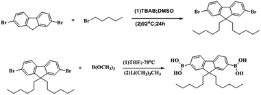 | ||
| Scheme 1 Preparation of 9,9-dihexyl-2,7-dibromofluorene and 9,9-dihexylfluoren-2,7-yldiboronic acid. | ||
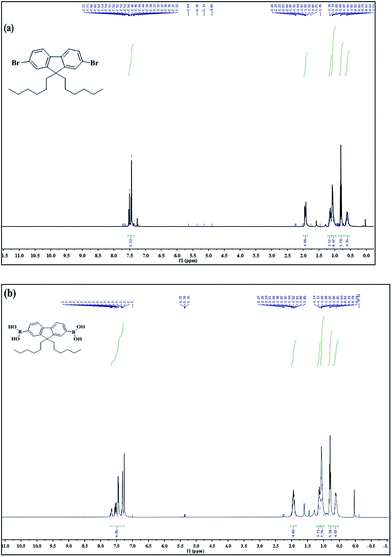 | ||
| Fig. 1 1H-NMR (400 MHz, CDCl3) of 9,9-dihexyl-2,7-dibromofluorene (a) and 9,9-dihexylfluoren-2,7-yldiboronic acid (b). | ||
2.4 Synthesis of 9,9-dihexylfluoren-2,7-yldiboronic acid
In a typical procedure, 2,7-dibromo-9,9-dihexylfluorene (4.14 g, 8.4 mmol) and 50 mL anhydrous THF were added to a 100 mL two-necked round-bottom flask under a nitrogen atmosphere. Then, n-butyl lithium (4.8 mL, 2.5 M) was slowly added at −78 °C. After an hour, anhydrous trimethyl borate (0.56 mL, 5 mmol) was added dropwise to the mixture. After 30 min, the mixture was cooled down to room temperature and stirred overnight. Finally, 20 mL H2O was added to terminate the reaction, and then, the mixture was extracted with diethyl ether and dried with anhydrous magnesium sulfate. After removing the solvent, a white solid was obtained. The synthetic route is shown in Scheme 1. Fig. 1(b): 1H NMR (400 MHz, chloroform-d) δ 7.69–7.29 (m, 6H), 2.00–1.89 (m, 4H), 1.18–1.09 (m, 4H), 1.08–1.04 (m, 8H), 0.79 (t, J = 5.6 Hz, 6H), 0.64–0.60 (m, 4H).2.5 Synthesis of G-PBTH via the Suzuki coupling reaction
Br-Gra was dispersed in 30 mL DMF solvent in a two-necked round-bottom flask equipped with a magnetic bar. Then, 0.412 g sodium carbonate, 0.25 g (0.59 mmol) 9,9-dihexylfluorene-2,7-boronic acid, and 0.1 g tetrabutylammonium bromide were added to the dispersion. The reaction mixture was degassed by purging with nitrogen and evacuating sequentially for three times. Then, 20 mg tetrakis triphenylphosphine palladium, which was dissolved in 10 mL THF, was injected into the reaction mixture. Subsequently, the reaction solution was refluxed for 2 h at 100 °C. Next, 0.09 g (0.59 mmol) 4,7-dibromo-2,1,3-benzothiadiazole in THF (10 mL) solution was injected to the reaction mixture and refluxed for 72 h at the same temperature in a N2 atmosphere. Finally, the mixture was precipitated with a 100 mL mixture of HCl![[thin space (1/6-em)]](https://www.rsc.org/images/entities/char_2009.gif) :
:![[thin space (1/6-em)]](https://www.rsc.org/images/entities/char_2009.gif) methanol = 1
methanol = 1![[thin space (1/6-em)]](https://www.rsc.org/images/entities/char_2009.gif) :
:![[thin space (1/6-em)]](https://www.rsc.org/images/entities/char_2009.gif) 100 and washed with methanol and water. Further purification was conducted by washing with refluxed acetone in a Soxhlet extractor for 2 days and drying under vacuum at room temperature; a brown solid was obtained. Additionally, PFBT was synthesized in the same way as G-PFBT except graphene. The synthetic route is shown in Scheme 2.
100 and washed with methanol and water. Further purification was conducted by washing with refluxed acetone in a Soxhlet extractor for 2 days and drying under vacuum at room temperature; a brown solid was obtained. Additionally, PFBT was synthesized in the same way as G-PFBT except graphene. The synthetic route is shown in Scheme 2.
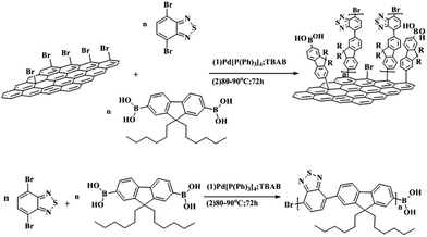 | ||
| Scheme 2 Synthesis of poly(fluorene-benzothiadiazole) (PFBH) and poly(fluorene-benzothiadiazole)-graphene (G-PFBH). | ||
2.6 Fabrication of the solar cells
Polymer solar cells were manufactured according to the following procedure: the ITO-coated glass substrate was first cleaned with detergent, ultrasonicated in acetone and isopropyl alcohol, and subsequently dried in an oven overnight. Highly conducting PEDOT:PSS with the thickness ∼40 nm was spin-cast (3000 rpm) from an aqueous solution. The substrate was dried for 15 min at 120 °C in air and then moved into a glove-box for spin-casting the photoactive layer. The THF solution G-PFBT (60 nm) was then spin-cast at 700 rpm on top of the PEDOT:PSS layer. Subsequently, the device was pumped down in vacuum (<10−7 torr), and a ∼80 nm Al film was deposited on top of the active layer. Thermal annealing was carried out by directly placing the completed device on a digitally controlled hotplate at various temperatures in a glove-box filled with nitrogen gas. After annealing, the device was placed on a metal plate and cooled to room temperature before the measurements were carried out. The structure of the solar cell is shown in Scheme 3.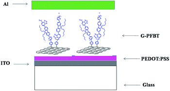 | ||
| Scheme 3 A schematic of the device configuration of hybrid solar cells:31 ITO/PEDOT:PSS/G-PFBT/Al. | ||
2.7 Characterization
Fourier transform infrared (FTIR) and ultraviolet-vis spectroscopy (UV-vis) spectra were obtained using a Perkin-Elmer 983 and S-3100 spectrophotometer, respectively. The 1H-NMR spectra were obtained using a Varian MecryPlus 400NB at room temperature with TMS as the internal standard. Fluorescence emission spectra were obtained using an AB-series 2 luminescence spectrometer. The power conversion efficiencies were measured via an Oriel Sol2AABA solar simulator from American NEWPORT company.3. Results and discussion
3.1 FTIR spectra analysis
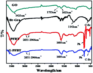
The evidence of successful functionalization following the covalent coupling of the polymer on graphene can be obtained from the FTIR spectra. The FTIR spectra for GO, Br-Gra, PFBT, and G-PFBT are shown in Fig. 2. The FTIR spectrum of GO is characterized by vibrational bands corresponding to the C–O (epoxy) stretching at 1285 cm−1, the O–H-deformation vibration at 1416 cm−1, the benzenoid C![[double bond, length as m-dash]](https://www.rsc.org/images/entities/char_e001.gif) C-stretching vibration at 1625 cm−1, and the C
C-stretching vibration at 1625 cm−1, and the C![[double bond, length as m-dash]](https://www.rsc.org/images/entities/char_e001.gif) O stretching at 1733 cm−1. Compared with that of GO, for Br-Gra, the intensity of the C–O stretching frequency at 1285 cm−1 decreased. Additionally, C–Br bending vibration in Br-Gra can be seen at 561 cm−1. This shows that the reduction of GO is incomplete and the bromination of graphene is successful. In the spectrum of G-PFBT, the bands at 1142 cm−1 and 561 cm−1 can be attributed to the aromatic in-plane C–H bending vibration and C–Br bond in Br-Gra, respectively. Moreover, the presence of PFBT is investigated by the appearance of four absorption bands at 730 cm−1, 1605 cm−1, 2831 cm−1, and 2966 cm−1 associated with the aromatic out-of-plane C–H-bending vibration of the phenyl group, the benzenoid C
O stretching at 1733 cm−1. Compared with that of GO, for Br-Gra, the intensity of the C–O stretching frequency at 1285 cm−1 decreased. Additionally, C–Br bending vibration in Br-Gra can be seen at 561 cm−1. This shows that the reduction of GO is incomplete and the bromination of graphene is successful. In the spectrum of G-PFBT, the bands at 1142 cm−1 and 561 cm−1 can be attributed to the aromatic in-plane C–H bending vibration and C–Br bond in Br-Gra, respectively. Moreover, the presence of PFBT is investigated by the appearance of four absorption bands at 730 cm−1, 1605 cm−1, 2831 cm−1, and 2966 cm−1 associated with the aromatic out-of-plane C–H-bending vibration of the phenyl group, the benzenoid C![[double bond, length as m-dash]](https://www.rsc.org/images/entities/char_e001.gif) C-stretching vibration, symmetric C–H stretch, and aliphatic asymmetric C–H stretch of the alkyl groups of 9,9-dihexylfluorene and benzothiadiazole monomer, respectively. Thus, all these observations confirm the formation of a covalent bond between graphene and PFBT.25
C-stretching vibration, symmetric C–H stretch, and aliphatic asymmetric C–H stretch of the alkyl groups of 9,9-dihexylfluorene and benzothiadiazole monomer, respectively. Thus, all these observations confirm the formation of a covalent bond between graphene and PFBT.25
3.2 UV-vis absorption spectra analysis
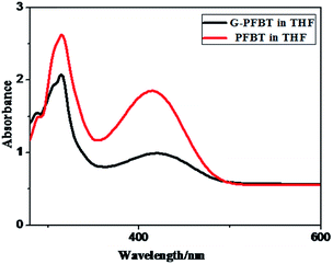
Fig. 3 shows the normalized absorption spectra of PFBT and G-PFBT in the THF solution. Both polymers show broad absorption ranging from 200 nm to 500 nm, which is wider than that of PF and G-PF (from 200 nm to 400 nm).20 The absorption maximum at 416 nm attributable to the π–π* transition was observed for PFBT, which redshifted to about 424 nm upon grafting of PFBT onto graphene in G-PFBT. However, the simple mixture of PFBT and graphene under the same conditions did not display any significant change in the PFBT absorption band. These results for grafted graphene materials again demonstrate covalent bonding between the conjugated system (PFBT) and graphene and indicate that a strong interaction exists between PFBT and graphene in G-PFBT.18,28 The specific interaction probably increases the electron delocalization along the polymer chain, thus leading to the observed red-shift of the optical absorption peak. Obviously, the conjugated polymer has broad absorption of visible light that is desirable for a photoactive material.26To investigate the absorption behavior of the composite film, PFBT and G-PFBT films were prepared by spin-coating from a THF (10 mg mL−1) solution. The normalized UV-vis absorption spectra for thin films of PFBT and G-PFBT are shown in Fig. 4. As expected, the PFBT thin film showed a significant red-shift of the π–π* absorption up to 440 nm from the corresponding solution absorption at 416 nm, most probably attributed to the aggregation of the PFBT rings.26 The absorption band of the G-PFBT film also showed a remarkable red-shift up to 470 nm from the corresponding solution absorption at 424 nm. The graphene-induced enhancement in electron delocalization along the chemically grafted PFBT chains was also observed in the G-PFBT film, as evidenced by about 30 nm red-shift in the absorption band of the G-PFBT film as compared to that of the PFBT film.
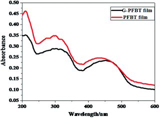 | ||
| Fig. 4 UV-vis absorption spectra of the PFBT and G-PFBT solid film prepared by spin-coating on quartz plates. | ||
The observed redshifts for the π–π* absorption band of G-PFBT in both the solution and the film upon grafting of PFBT on graphene indicate enhanced electron delocalization through charge transfer with the chemically conjugated graphene sheet to reduce the band gap energy.16 This suggested that the grafted graphene G-PFBT material was successfully synthesized and showed potential for applications in photovoltaic devices.
As shown in Fig. 3, the absorption band edge of G-PFBT and PFBT is 500 nm, according to the formula of bandgap energy gap: Eg = hc/eλ = 2.48 eV. This indicates excellent performance of semiconductor materials that can be widely used in optoelectronic devices.27
3.3 Fluorescence emission spectra analysis
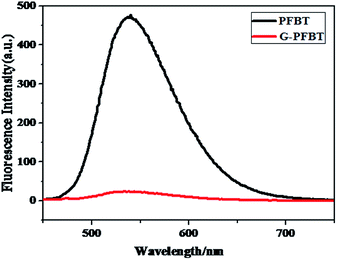
To further confirm successful covalent grafting of PFBT on Br-Gra sheets, photoluminescence measurement was carried out in the solution state for pure PFBT and G-PFBT composite.26 The fluorescence spectra of G-PFBT and PFBT measured in THF were compared, as shown in Fig. 5, by normalizing the π–π* absorption peak. It is clearly shown that with the introduction of graphene, the photoluminescence intensity of G-PFBT is remarkably reduced. The intensity at 540 nm was quenched by 95% as compared to that of PFBT, which again indicates that PFBT was grafted on the Br-Gra sheet and suggests a strong molecular interaction between PFBT and graphene.29 The completely quenched emission in G-PFBT indicated an effective electron or energy transfer between PFBT and graphene.30 These results were also discovered by Kian Ping Loh.25 A study on PFBT and graphene shows that it is very likely that graphene can act as an active electron-accepting material for photovoltaic applications.31,323.4 Solubility of the PFBT and G-PFBT
As shown in Fig. 6, PFBT and G-PFBT exhibit yellow and green color in THF, respectively. Compared with Br-Gra,20 G-PFBT displayed much better solubility in common organic solvents such as THF and toluene. The change in the observed color indicates that there is a strong interaction between the excited state of PFBT and graphene in the hybrids. This can be ascribed to the electron and energy transfer between two conjugated systems, which is facilitated by the direct linkage mode of the two moieties via the C–C bonds. The intermolecular donor–acceptor interaction between two moieties may involve charge transfer from the aryl group to graphene.24 Moreover, PFBT and G-PFBT can be readily processed to form smooth and pinhole-free films upon spin-coating from a THF solution. Accordingly, it is obvious that favorable solubility in solvents as well as the π-conjugated structure make graphene an ideal candidate for various applications.15,16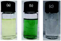 | ||
| Fig. 6 Images of PFBT (a), G-PFBT (b); 5 mg of PFBT and G-PFBT dispersed in 10 mL of THF; 5 mg of Br-Gra (c) dispersed in 10 mL H2O. | ||
3.5 Photovoltaic performances of the solar cell
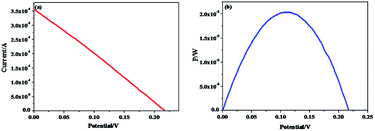
As shown in Fig. 7, G-PFBT polymer photovoltaic cells with the structure of ITO/PEDOT:PSS (40 nm)/G-PFBT (60 nm)/Al (80 nm) were fabricated. Scheme 3 shows the structure of the polymer solar cell together with the chemical structure of its components.34 The charge-separation layer for the cell is a bulk heterojunction composite of poly(fluorene-benzothiadiazole)-graphene (G-PFBT).5,35 Fig. 7(a) shows the current–voltage (I–V) curve for photovoltaic cell, and Fig. 7(b) shows the power–voltage (P–V) curve for the cell. Upon 80 mW cm−2 (AM1.5G) illumination, however, an open-circuit voltage (Voc) of 0.22 V and short-circuit current density (Jsc) of 1.42 mA cm−2 was observed. As per the graph shown in Fig. 7(b), Pmax was found to be 2 × 10⁻⁵ W; according to eqn (1), we can calculate FF = 0.26. According to eqn (2), overall power conversion of 0.1% was obtained for the device.7,36Fill factor (FF) was calculated using the following equations:
 | (1) |
The power conversion efficiency (η) has been calculated using the equation:
 | (2) |
As we can see, the power conversion efficiency for the device is slightly low. There may be two aspects of explanation: on the one hand, it is difficult to obtain a homogeneous film via direct spin coating in the solution process, and there is interlayer mixing that affects the adequacy and integrity of the network formed by the electron donor–acceptor system, thereby affecting the charge transfer process and ultimately affecting the performance of the entire device.33 On the other hand, graphene easily aggregates in the solution state; after accumulation, most of the surface disappears and its unique characteristics no longer exist. Thus, the photoelectric properties of the polymer will be affected.16 However, G-PFBT forms a system of an electron donor–acceptor network itself, which is connected by a covalent bond between PFBT and graphene, resulting in an increase in the surface area of electron donor–acceptor network in the active layer and improvement of the separation efficiency of photogenic excitation. This is significant for the study of optics devices. Furthermore, the relatively low power conversion efficiency for the device indicates considerable space for further improvement in the device performance.
4. Conclusions
In summary, conjugated PFBT has been covalently grafted on graphene sheets successfully via Suzuki coupling reaction. Results of the UV spectroscopy revealed that the Eg of G-PFBT was 2.48 eV, similar to the band gap of semiconductors. Photoinduced charge transfer and good solubility were observed for the composite G-PFBH, which were favorable for photovoltaic device. Solar cell based on G-PFBH exhibits a Voc, Jsc, FF, and overall power conversion efficiency of 0.22 V, 1.42 mA cm−2, 0.26, and 0.1%, respectively. This study not only develops the application of conjugated polymer-grafted graphene materials, but also provides guidance for the optimization of photovoltaic devices.Acknowledgements
This work was supported by the Fundamental Research Funds for the Central Universities (CUGL100407, CUG120118), the National Natural Science Foundation of China (50903077), the Natural Science Foundation of Hubei Province (2010BFA022, 2011CDA035), and the Public Service Project of the Chinese Ministry of Land and Resources (201311024).References
- H. Hoppe and N. S. Sariciftci, Organic solar cells: an overview, J. Mater. Res., 2004, 19(7), 1924–1945 CrossRef CAS.
- M. Drees, H. Hoppe and C. Winder, et al., Stabilization of the nanomorphology of polymer–fullerene “bulk heterojunction” blends using a novel polymerizable fullerene derivative, J. Mater. Chem., 2005, 15(48), 5158–5163 RSC.
- C. T. Barry and M. J. F. Jean, Polymer–fullerene composite solar cells, Angew. Chem., Int. Ed., 2008, 47(1), 58–77 CrossRef PubMed.
- G. Yu, J. Gao and J. C. Hummelen, et al., Polymer photovoltaic cells – enhanced efficiencies via a network of internal donor–acceptor heterojunctions: enhanced efficiencies via a network of internal donor–acceptor heterojunctions, Science, 1995, 270(5243), 1789–1791 CAS.
- J. You, L. Dou and K. Yoshimura, et al., A polymer tandem solar cell with 10.6% power conversion efficiency, Nat. Commun., 2013, 4(1446), 66–78 Search PubMed.
- Y. Liang, D. Feng and Y. Wu, et al., Highly efficient solar cell polymers developed via fine-tuning of structural and electronic properties, J. Am. Chem. Soc., 2009, 131(22), 7792–7799 CrossRef CAS PubMed.
- J. Yuan, J. Gu and G. Shi, et al., High efficiency all-polymer tandem solar cells, Sci. Rep., 2016, 6, 1–7 CrossRef PubMed.
- P. A. Troshin, H. Harald and R. Joachim, et al., Material solubility–photovoltaic performance relationship in the design of novel fullerene derivatives for bulk heterojunction solar cells, Adv. Funct. Mater., 2015, 19(5), 779–788 CrossRef.
- K. S. Novoselov, A. K. Geim and S. V. Morozov, et al., Electric field effect in atomically thin carbon films, Science, 2004, 306(5696), 666–669 CrossRef CAS PubMed.
- K. S. Novoselov, S. V. Morozov and T. M. G. Mohinddin, et al., Electronic properties of graphene, Rev. Mod. Phys., 2007, 83(10), 1248–1252 Search PubMed.
- K. I. Bolotin, K. J. Sikes and Z. Jiang, et al., Ultrahigh electron mobility in suspended graphene, Solid State Commun., 2008, 146(9–10), 351–355 CrossRef CAS.
- Y. Zhu, S. Murali and W. Cai, et al., Graphene and graphene oxide: synthesis, properties, and applications, Adv. Mater., 2010, 22(35), 3906–3924 CrossRef CAS PubMed.
- S. V. Morozov, K. S. Novoselov and M. I. Katsnelson, et al., Giant intrinsic carrier mobilities in graphene and its bilayer, Phys. Rev. Lett., 2008, 100(1), 145–150 CrossRef PubMed.
- C. Lee, X. Wei and J. W. Kysar, et al., Measurement of the elastic properties and intrinsic strength of monolayer graphene, Science, 2008, 321(5887), 385–388 CrossRef CAS PubMed.
- Q. Su, S. Pang and V. Alijani, et al., Composites of graphene with large aromatic molecules, Adv. Mater., 2009, 21(31), 3191–3195 CrossRef CAS.
- D. Yu, Y. Yang and M. Durstock, et al., Soluble P3HT-grafted graphene for efficient bilayer-heterojunction photovoltaic devices, ACS Nano, 2010, 4(10), 5633–5640 CrossRef CAS PubMed.
- M. C. Arenas, N. Mendoza and H. Cortina, et al., Influence of poly3-octylthiophene (P3OT) film thickness and preparation method on photovoltaic performance of hybrid ITO/CdS/P3OT/Au solar cells, Sol. Energy Mater. Sol. Cells, 2010, 94(1), 29–33 CrossRef CAS.
- M. Svensson, F. Zhang and S. C. Veenstra, et al., High-performance polymer solar cells of an alternating polyfluorene copolymer and a fullerene derivative, Adv. Mater., 2003, 15(12), 988–991 CrossRef CAS.
- Q. Liu, Z. Liu and X. Zhang, et al., Organic photovoltaic cells based on an acceptor of soluble graphene, Appl. Phys. Lett., 2008, 92(223303), 1–3 Search PubMed.
- J. Gao, F. Bao and Q. Zhu, et al., Attaching hexylbenzene and poly(9,9-dihexylfluorene) to brominated graphene via Suzuki coupling reaction, Polym. Chem., 2013, 4(5), 1672–1679 RSC.
- Y. Yao, J. Gao and F. Bao, et al., Covalent functionalization of graphene with polythiophene through a Suzuki coupling reaction, RSC Adv., 2015, 5(53), 42754–42761 RSC.
- J. F. Colomer, R. Marega and H. Traboulsi, et al., Microwave-assisted bromination of double-walled carbon nanotubes, Chem. Mater., 2009, 21(20), 4747–4749 CrossRef CAS.
- J. F. Friedrich, S. Wettmarshausen and S. Hanelt, et al., Plasma-chemical bromination of graphitic materials and its use for subsequent functionalization and grafting of organic molecules, Carbon, 2010, 48(13), 3884–3894 CrossRef CAS.
- Z. B. Liu, Y. F. Xu and X. Y. Zhang, et al., Porphyrin and fullerene covalently functionalized graphene hybrid materials with large nonlinear optical properties, J. Phys. Chem. B, 2009, 113(29), 9681–9686 CrossRef CAS PubMed.
- A. Midya, V. Mamidala and J. X. Yang, et al., Synthesis and superior optical-limiting properties of fluorene–thiophene–benzothiadiazole polymer-functionalized graphene sheets, Small, 2010, 6(20), 2292–2300 CrossRef CAS PubMed.
- J. Hou, Z. Tan and Y. Yan, et al., Synthesis and photovoltaic properties of two-dimensional conjugated polythiophenes with bi(thienylenevinylene) side chains, J. Am. Chem. Soc., 2006, 128(14), 4911–4916 CrossRef CAS PubMed.
- J. Pei, J. Tao and Y. Zhou, et al., Efficiency enhancement of polymer solar cells by incorporating a self-assembled layer of silver nanodisks, Sol. Energy Mater. Sol. Cells, 2011, 95(12), 3281–3286 CrossRef CAS.
- Y. Liang, D. Wu and X. Feng, et al., Dispersion of graphene sheets in organic solvent supported by ionic interactions, Adv. Mater., 2009, 21(17), 1679–1683 CrossRef CAS.
- Y. Suzuki, A. Kazuhito Hashimoto and K. Tajima, Synthesis of regioregular poly(p-phenylenevinylene)s by Horner reaction and their regioregularity characterization, Macromolecules, 2007, 40(18), 6521–6528 CrossRef CAS.
- J. Zou, L. Liu and H. Chen, et al., Dispersion of pristine carbon nanotubes using conjugated block copolymers, Adv. Mater., 2008, 20(11), 2055–2060 CrossRef CAS.
- Z. Liu, Q. Liu and Y. Huang, et al., Organic photovoltaic devices based on a novel acceptor material: graphene, Adv. Mater., 2008, 20(20), 3924–3930 CrossRef CAS.
- Z. Yang, X. Shi and J. Yuan, et al., Preparation of poly(3-hexylthiophene)/graphene nanocomposite via in situ reduction of modified graphite oxide sheets, Appl. Surf. Sci., 2010, 257(1), 138–142 CrossRef CAS.
- J. Y. Kim, K. Lee and N. E. Coates, et al., Efficient tandem polymer solar cells fabricated by all-solution processing, Science, 2007, 317(5835), 222–225 CrossRef CAS PubMed.
- S. E. Shaheen, C. J. Brabec and N. S. Sariciftci, et al., 2.5% efficient organic plastic solar cells, Appl. Phys. Lett., 2001, 78(6), 841–843 CrossRef CAS.
- T. Kim, J. H. Kim and T. E. Kang, et al., Flexible, highly efficient all-polymer solar cells, Nat. Commun., 2015, 6, 1–7 Search PubMed.
- H. Wei, Y. H. Chao and C. Kang, et al., High-efficiency large-bandgap material for polymer solar cells, Macromol. Rapid Commun., 2015, 36(1), 84–89 CrossRef CAS PubMed.
- S. Lu, S. S. Sun and X. Jiang, et al., In situ 3-hexylthiophene polymerization onto surface of TiO2, based hybrid solar cells, J. Mater. Sci.: Mater. Electron., 2010, 21(7), 682–686 CrossRef CAS.
Footnote |
| † Electronic supplementary information (ESI) available: The process of power conversion efficiency measurement. See DOI: 10.1039/c7ra05937j |
| This journal is © The Royal Society of Chemistry 2017 |

