 Open Access Article
Manganese dioxide core–shell nanostructure to achieve excellent cycling stability for asymmetric supercapacitor applications
Quanbing Liua,
Juan Yangb,
Rongfang Wang *b,
Hui Wangb and
Shan Ji*ac
aSchool of Chemical Engineering and Light Industry, Guangdong University of Technology, Guangzhou 510006, China. E-mail: jissshan@126.com
bInstitute of Chemical Engineering, Qingdao University of Science and Technology, Qingdao, 266042, China
cCollege of Biological, Chemical Science and Chemical Engineering, Jiaxing University, Jiaxing, 314001, China
First published on 3rd July 2017
Abstract
This study presents a facile and low-cost method to prepare core–shell nano-structured β-MnO2@δ-MnO2, in which β-MnO2 nano-wires act as the cores to form 3D networks and δ-MnO2 as the shells. A uniform hierarchical β-MnO2@δ-MnO2 core–shell structure can be obtained after layered structured δ-MnO2 is deposited on the surface of the needle-like β-MnO2 particles via a simple wet chemistry method at room temperature. The as-prepared materials were physically and electrochemically characterized by nitrogen isotherm analysis, X-ray diffraction, scanning electron microscopy, transmission electron microscopy and potentiostatically/galvanostatically. Under our conditions, the electrochemical results showed that the specific capacitance of β-MnO2@δ-MnO2 was ∼200 F g−1 and the specific capacitance retention was almost 100% after 5000 cycles at a current density of 1 A g−1 in 1 M LiOH electrolyte. The excellent cycling stability of β-MnO2@δ-MnO2 showed that the new material has great potential for use in electrochemical supercapacitors, and the facile wet chemistry method used to synthesize β-MnO2@δ-MnO2 could be a promising method to produce highly stable MnO2-based electrode materials in large batches.
1. Introduction
High-performance supercapacitors have received enormous interest as promising Energy Storage Devices (ESDs) for mobile electronics, backup power supplies and electric vehicles due to their high power density, fast charge/discharge capability and long cycle life.1–4 Electrochemical supercapacitors using MnO2 as electrode materials have attracted significant attention; this is due to the fact that they possess high theoretical capacitance, large electrode potential window, and are low-cost, non-toxic and environmentally benign in comparison to those using ruthenium oxides or other transition metal oxide electrodes.5–8 MnO2 of various crystallographic polymorphs (such as α-, β-, δ-, γ- and ε-MnO2) consist of MnO6 units in which each Mn4+ is surrounded by six oxygen atoms.9 It was found that polymorphs consisting of MnO6 octahedra are interlinked yielding various structures with different tunnels or interlayers.10 Moreover, the charge storage in transition metal oxides is a multi-step process involving electrolyte ion transfer on the interface of the electrode/electrolyte and the intercalation/deintercalation of cations. Recent studies showed that materials possessing two-dimensional (2D) layered structure and wide interlayer spacing are ideal electrode materials for electrochemical supercapacitors, providing promising features, e.g. favouring the transport of electrolyte ions and the intercalation/deintercalation processes, leading to highly efficient ESDs.11The capacitance properties of MnO2 strongly rely upon the intercalation/deintercalation of cations into or from its structure in aqueous electrolytes, indicating that structures with large size tunnels or interlayers result in better capacitance performance.10 Among all these MnO2 polymorphs, δ-MnO2 with edge-shared MO6 octahedra have shown to exhibit decent electrochemical performances, making it a promising electrode material for electrochemical supercapacitors;10,12,13 this is due to the fact that this polymorph is a two-dimensional layer-structured material with a relatively large interlayer distance (∼7.0 Å). Recently, many studies have focused on routes and techniques for the preparation of δ-MnO2. For example, Li et al. reported that δ-MnO2 synthesized by a microwave-hydrothermal method under low pressure exhibited a specific capacitance of 210 F g−1 at a current density of 200 mA g−1 in a 1.0 M Na2SO4 electrolyte.14 Ji et al. deposited hierarchical δ-MnO2 nano-sheets directly onto a nickel foam substrate using a one-pot chelation-mediated aqueous method, and the as-prepared material exhibited a relatively high capacitance of 325 F g−1 at a current density of 1 A g−1.15 Zhang et al. synthesized δ-MnO2/holey graphene hybrid fibre by activating graphene fibre in a H3PO4 solution, followed by the deposition of δ-MnO2 on its surface.16 The electrochemical results showed that the obtained material exhibited a large specific capacitance of 245 F g−1 at a current density of 1 A g−1 in a 1 M Na2SO4 solution. Although many efforts have been devoted to the preparation of δ-MnO2 material for electrochemical supercapacitors, it still remains a challenge to obtain δ-MnO2 with good cycling capability and stability. This is because (a) these 2D layered nano-structures often result in low electronic properties due to the poor contacts between each other and (b) their crystal structures are not stable under the electrochemical reactions.17,18
In order to improve the cycling stability and achieve better electrochemical performance of δ-MnO2, an alternative and promising way is to develop hierarchical structures using different types of metal oxides. One-dimensional (1D) MnO2 nano-sized materials can provide reliable electrical contact between the 1D nano-sized MnO2 particles due to the formation of the three-dimensional (3D) network.17 A hierarchical structure combining a 1D β-MnO2 with a 2D δ-MnO2 could result in better electrochemical performances due to (a) the good electrical conductivity of the 1D structure and, (b) the high surface area for ion adsorption on the 2D architecture improving the diffusion of the charge carriers. Also, there are many rooms in such hierarchical structure which can effectively buffer any volume change during intercalation/deintercalation of cations.19
In this study, the authors present a facile and low-cost approach for producing hierarchical core–shell structured mixed phase manganese oxides, consisting of β-MnO2 nano-wires acting as the core to form 3D networks and δ-MnO2 covered on its surface as the shell. In this investigation, the authors had for objective to produce a particle architecture that combines layered structure δ-MnO2 supported on β-MnO2 nano-wires. Through this unusual structural design, the obtained core–shell structured manganese oxide exhibited both high cycling stability and high electrochemical performance.
2. Experimental
2.1 Preparation of the samples
All reagents were of analytic grade (AR) and double-distilled water was used all throughout the experiments. To prepare the 1D β-MnO2 nano-wires, 8 mmol of MnSO4 and 8 mmol of (NH4)2SO4 were added to 60 mL H2O under intense stirring (magnetic stirrer). Then this solution was transferred to a 100 mL Teflon-lined stainless-steel autoclave and heated at 120 °C for 12 h. The autoclave was cooled to room temperature, and the product was filtered, washed with water and dried at 80 °C for 12 h. The resultant material was made of 1D β-MnO2 nano-wires.To prepare β-MnO2@δ-MnO2, 60 mg of the as-prepared 1D β-MnO2 nano-wires was added to 30 mL of 0.41 mmol MnSO4 solution and ultrasonicated for 10 min using an ultrasonic bath operating at 40 kHz. The obtained mixture was dropwise added to 20 mL of 0.28 KMnO4 solution and then kept at room temperature for 30 min. Then the product was collected (centrifuge), filtered, washed with water, and finally dried at 80 °C for 12 h. The obtained product was made of β-MnO2@δ-MnO2.
For comparison purposes, pure δ-MnO2 was also prepared and the detail procedure is as follows: 30 mL of 0.41 mmol MnSO4 was dropwise added to 20 mL of 0.28 KMnO4 solution. The reaction was further allowed to proceed at room temperature for 30 min. The obtained pure δ-MnO2 was filtered, washed with water and dried at 80 °C for 12 h.
2.2 Physical characterizations
XRD patterns were recorded on a Shimadzu XD-3A (Japan) using filtered Cu-Kα radiation (λ = 0.15418 nm) generated at 40 kV and at 30 mA. Scans for 2θ values were recorded at 4° min−1. Scanning electron microscopy (SEM) images were obtained using a Carl Zeiss Ultra Plus. Transmission electron microscopy (TEM) high angle annular dark field scanning transmission electron microscopy (STEM) images and selected area electron diffraction (SAED) patterns of the catalysts were obtained using a JEOL (JEM-2000 FX) microscope operating at 200 kV. Line-scan energy dispersive spectroscopy (EDS) in the STEM mode was used for elemental composition analysis. The sorption isotherms were obtained on a Quantachrome Autosorb-1 volumetric analyzer. Specific surface areas were determined by the Brunauer–Emmett–Teller (BET) method.2.3 Electrochemical characterizations
Cyclic voltammograms (CV) and galvanostatic charge/discharge experiments on the as-prepared materials were carried out in a three-electrode electrochemical cell. The working electrode (WE) consisted of a film (1 cm2) containing β-MnO2@δ-MnO2 (10 mg), carbon black and poly(tetrafluoroethylene) with a mass ratio of 80![[thin space (1/6-em)]](https://www.rsc.org/images/entities/char_2009.gif) :
:![[thin space (1/6-em)]](https://www.rsc.org/images/entities/char_2009.gif) 10
10![[thin space (1/6-em)]](https://www.rsc.org/images/entities/char_2009.gif) :
:![[thin space (1/6-em)]](https://www.rsc.org/images/entities/char_2009.gif) 10, pressed into the Ni foam current collectors. An Hg/HgO (1.0 M KOH) reference electrode (REF) and an activated carbon counter electrode (CE) was used in all experiments in 1 mol L−1 LiOH electrolyte. CV experiments were performed on a CHI 650D electrochemical workstation. Galvanostatic charge/discharge tests were carried out on a Neware Battery Tester (BTS6.0, Neware Technology Company, Guangdong, China).
10, pressed into the Ni foam current collectors. An Hg/HgO (1.0 M KOH) reference electrode (REF) and an activated carbon counter electrode (CE) was used in all experiments in 1 mol L−1 LiOH electrolyte. CV experiments were performed on a CHI 650D electrochemical workstation. Galvanostatic charge/discharge tests were carried out on a Neware Battery Tester (BTS6.0, Neware Technology Company, Guangdong, China).
3. Results and discussion
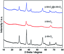
Fig. 1 shows the powder X-ray diffraction (XRD) patterns of β-MnO2, δ-MnO2 and β-MnO2@δ-MnO2. The XRD pattern of β-MnO2 shows the typical peak dispersion indexed to β-MnO2 tetragonal phase (Joint Committee on Powder Diffraction Standards [JCPDS] Card 24-0735), in which no peaks related to other types of MnO2 or amorphous MnO2 are observed, indicative of the formation of highly pure and crystalline β-MnO2. The diffraction peaks of δ-MnO2, synthesized at room temperature, are exhibited at angles of 37.2° and 67.2° which are ascribed to (111) and (021) planes of δ-MnO2 (JCPDS Card: 42-1317) respectively. However, these peaks are small and weak, indicating that the as-prepared δ-MnO2 particles are small and poorly crystalline. Similar XRD patterns of δ-MnO2 were also found in the literature where the δ-MnO2 samples were prepared at low temperature.15,20,21 In the case of β-MnO2@δ-MnO2, its XRD pattern shows no obvious difference from β-MnO2, for example the peaks resemble to those associated to a β-MnO2 structure indicating that a small amount of δ-MnO2 was formed on the surface of β-MnO2.Scanning electron microscope (SEM) and transmission electron microscope (TEM) images of β-MnO2 and β-MnO2@δ-MnO2 are shown in Fig. 2(A). shows that the as-prepared β-MnO2 particles are needle-like in shape and have a size of ca. 2–5 μm in length by direct statistic observation. The figure also shows that there is no presence of other forms of particles, indicating that highly pure β-MnO2 with uniform morphology was formed, which is in very good agreement with the XRD results. SEM image of δ-MnO2 is shown in Fig. 2(C), which comprise irregular particles and many particles aggregated into large particles. As shown in Fig. 2(B), a uniform hierarchical β-MnO2@δ-MnO2 core–shell structure was formed after the δ-MnO2 was deposited on the surface of β-MnO2 via the simple wet chemistry method at room temperature. From the figure, it can be seen that the δ-MnO2 is hardly formed in the spaces between the β-MnO2 nano-wires, implying that the formation of δ-MnO2 preferentially occurs on the surface of β-MnO2 nano-wires resulting in an uniform β-MnO2@δ-MnO2 core–shell structure. Fig. 2(E) shows a typical TEM image of β-MnO2@δ-MnO2. The figure shows that the β-MnO2 has a uniform nanowire structure with a diameter of ca. 70 nm. It can also be seen that δ-MnO2 was uniformly distributed on the surface of β-MnO2 nano-wires with a thickness of ca. 30 nm. However, there is no obvious evidence of boundaries between the β-MnO2 core and δ-MnO2 shell, showing that an intimate contact between these two different phases of MnO2 exists. On the edge of the δ-MnO2 shell, ultra-thin δ-MnO2 nano-sheets are found and expected to provide improved electrochemical properties. Fig. 2(F) shows a detailed microstructure of the core and shell of β-MnO2@δ-MnO2, in which the atomic plane arrangement of β-MnO2 is clearly present, but with the absence of an atomic plane in the shell of δ-MnO2. This finding further confirms that the δ-MnO2 grown on the surface of β-MnO2 is small and is of a poor crystalline structure. It is also observed that the δ-MnO2 shell with layered structure was formed on the surface of β-MnO2 nano-wires. Such a layered structure is expected to facilitate the intercalation/deintercalation of cations into and from the electrode materials resulting in an improved electrochemical capacitance performance.
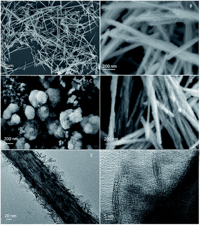 | ||
| Fig. 2 SEM images of β-MnO2 (A), β-MnO2@δ-MnO2 (B), δ-MnO2 (C) and β-MnO2@δ-MnO2 after 5000 cycles (D), TEM image of β-MnO2@δ-MnO2 (E) and HRTEM image of β-MnO2@δ-MnO2 (F). | ||
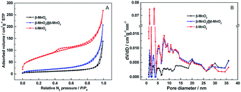
The porous structures of β-MnO2, δ-MnO2 and β-MnO2@δ-MnO2 were evaluated by N2 isotherm analysis (Fig. 3 and Table 1). The nitrogen adsorption–desorption isotherms of β-MnO2, shows a type II isotherm (as defined by the International Union of Pure and Applied Chemistry (IUPAC)) with a sharp capillary condensation step at a relative high pressure (P/P0 > 0.85). An hysteresis loop between adsorption and desorption curve could be considered as an H4-type, indicating a relatively large pore size, which could be due to the slit-shaped gap among the MnO2 crystals.22 The isotherm of β-MnO2@δ-MnO2 also exhibits type II with a hysteresis loop at a high relative pressure, indicating that the as-prepared material is of a mesoporous nature. The isotherms of δ-MnO2 is a mixed type in the IUPAC classification with a type I at a relative low pressure and a type II with an hysteresis loop at a relative intermediate and high pressure.23 At the initial part, there is an obvious uptake at a low relative pressure, which is a characteristic of a microporous structure. As shown in Fig. 3(B), the pore size distributions calculated from the Barrett–Joyner–Halenda (BJH) method show that the pore size distributions of δ-MnO2 and β-MnO2@δ-MnO2 are in the mesopore size range with a few micropores present. The BET surface area of δ-MnO2 was found to be 248.91 m2 g−1, which is ∼8 times higher than that of 1D β-MnO2 (30.06 m2 g−1). After δ-MnO2 was grown on the surface of needle-like 1D β-MnO2, the BET surface area of β-MnO2@δ-MnO2 was determined to be 56.44 m2 g−1, which is almost twice as high as that of β-MnO2, but still much lower than that of δ-MnO2, due to the presence of a thin layer of δ-MnO2 grown on β-MnO2.
| Samples | BET (m2 g−1) | Pore volume (cm3 g−1) |
|---|---|---|
| β-MnO2 | 30.06 | 0.214 |
| β-MnO2@δ-MnO2 | 56.44 | 0.321 |
| δ-MnO2 | 248.91 | 0.414 |
The electrochemical performance of the as-prepared β-MnO2, δ-MnO2 and β-MnO2@δ-MnO2 was evaluated by cyclic voltammetry (CV) and galvanostatic charge–discharge experiments in a three-electrode cell configuration and in 1 mol L−1 LiOH electrolyte. Fig. 4(A) shows the CVs of the β-MnO2, δ-MnO2 and β-MnO2@δ-MnO2 electrodes at a scan rate of 5 mV s−1 in 1.0 M LiOH solution and at room temperature. The figure shows that the CVs for the three samples exhibit a quasi-rectangular shape, typical of a pseudo-capacitive behaviour, with pairs of redox peaks corresponding to the reversible Faradaic redox reactions. The charge storage of MnO2-based electrodes results from the adsorption/desorption and the intercalation/deintercalation of cations or protons of the electrolyte.11 The morphology, crystal structure and surface area play an important role in storing the charges. The current response on δ-MnO2 is the highest among these three electrodes, suggesting that the high surface area and the layered structure favour the intercalation/deintercalation process as well as the adsorption/desorption occurring on the surface. On the β-MnO2@δ-MnO2 electrode, the current response is higher than that of the β-MnO2 electrode, indicating additional capacitive contribution from δ-MnO2 after it had been deposited on the surface of β-MnO2. Fig. 4(C) and (D) show the CVs of β-MnO2, δ-MnO2 and β-MnO2@δ-MnO2 electrodes carried out over the potential range of −0.15 to +0.60 V vs. Hg/HgO at various scan rates (5–100 mV s−1). When the scan rate increases from 5 to 100 mV s−1, the CVs of β-MnO2 still retain a quasi-rectangular shape, even though the Faradaic process revolves around the electrochemical behaviour of β-MnO2 in 1 M LiOH electrolyte, implying that the adsorption/desorption process dominates the charge storage process in β-MnO2. In the case of δ-MnO2 and β-MnO2@δ-MnO2, due to the layered structure of β-MnO2, the Faradaic process contributed proportionately more to the charge storage than the electrical double-layer capacitance. Therefore, with increasing the scan rate, the CVs of δ-MnO2 and β-MnO2@δ-MnO2 exhibit a distortion/change from quasi-rectangular shape due to electrode polarization. At fast scan rates, there is barely time for some Li+ ions to intercalate into the MnO2 structure due to the polarization of the desolvation process of Li+ ions, resulting in the CVs deviating from the quasi-rectangular shape.24
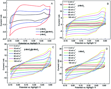 | ||
| Fig. 4 (A) CVs of β-MnO2, δ-MnO2 and β-MnO2@δ-MnO2 electrodes at scan rate of 5 mV s−1 and (B–D) their corresponding CVs at various scan rates (5–100 mV s−1) in 1 M LiOH. | ||
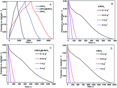
Fig. 5 shows the galvanostatic charge–discharge curves of the β-MnO2, δ-MnO2 and β-MnO2@δ-MnO2 at a current density of 50 mA g−1. All three electrodes present non-linear charge curves, asymmetric to their corresponding discharge curves (as shown in Fig. 5(A)), which is commonly and typically observed for pseudo-capacitive materials.25 The charge–discharge curves exhibit a quasi-plateau over the potential range from +0.3 to +0.5 V vs. Hg/HgO. This quasi-plateau could originate from the intercalation/deintercalation of Li+ into or from MnO2 structure which is consistent with the CV curves. The specific capacitance (Cs) values derived from the discharge curves were calculated using the following equation:
 | (1) |
The effect of the current density on the specific capacitance of β-MnO2, δ-MnO2 and β-MnO2@δ-MnO2 is shown in Fig. 6. It is clearly evident from the figure that the Cs for all three samples gradually decreased when the current densities increased from 0.05 to 5 A g−1. At the low current densities, all three electrodes show relatively high capacitance since the electrolyte ions have enough time to move to the interface of the electrode/electrolyte and take part to the intercalation/deintercalation process. At a current density of 5 A g−1, only a small portion of the material close to the surface can be utilized for storing the charge. The Cs of β-MnO2, δ-MnO2 and β-MnO2@δ-MnO2 at a current density of 5 A g−1 retain 38.4, 34.8 and 37.2 of their initial values at a current density of 0.1 A g−1, indicating that these three electrodes have similar rate capabilities.
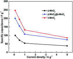 | ||
| Fig. 6 Specific capacitance of β-MnO2, δ-MnO2 and β-MnO2@δ-MnO2 at different current densities in 1 M LiOH electrolyte. | ||
Cycling stability is another critical requirement for high-performance supercapacitor. The cycling life tests for β-MnO2, δ-MnO2 and β-MnO2@δ-MnO2 were measured over 5000 continuous charge–discharge cycles between −0.15 to +0.6 V vs. Hg/HgO at a current density of 1 A g−1 as shown in Fig. 7.
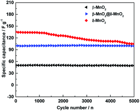 | ||
| Fig. 7 Cycling stability of β-MnO2, δ-MnO2 and β-MnO2@δ-MnO2 at a current density of 1 A g−1 in 1 M LiOH electrolyte. | ||
In the case of δ-MnO2, the Cs gradually decreases with increasing cycling numbers. After 5000 cycles, ca. 75% of its initial capacitance is retained. Compared to δ-MnO2, β-MnO2 and β-MnO2@δ-MnO2 show excellent cycling stability. After 5000 cycles, the specific capacitance retention of β-MnO2@δ-MnO2 is almost unchanged, and the coulombic efficiency of β-MnO2 is almost 100% (98.9%) as shown in Fig. 8, suggesting that the 1D β-MnO2 pocesses superior cycling stability and the hierarchical core–shell structured β-MnO2@δ-MnO2 using 1D β-MnO2 as backbones, retain the cycling stability of the 1D β-MnO2. The stability of β-MnO2@δ-MnO2 is also much greater than that of other reported MnO2-based electrode materials, such as NiCo2O4-doped carbon nanofiber@MnO2 core–sheath nanostructures,28 mesoporous MnO2/carbon aerogel composite,29 δ-MnO2 nanospheres14 and MnO2 core–shell nanowires.30 In terms of charge storage mechanism in MnO2-based electrodes,24 the charge storage process is based upon the adsorption/desorption of electrolyte ions, accompanied by redox conversion between Mn4+ and Mn3+. Based on this mechanism, the excellent cyclability of β-MnO2@δ-MnO2 could be attributed to the fact that the Faradic redox process occurred near the electrode surface, which in turns may not possibly cause serious modification in the crystal structure and morphology of the electrode material. The cycling stability testing causes negligible damage on the structure of β-MnO2@δ-MnO2, resulting in the excellent cycling stability. Although the surfaces of both β-MnO2@δ-MnO2 and δ-MnO2 were covered by layered structure δ-MnO2, β-MnO2@δ-MnO2 exhibits much better stability than δ-MnO2 since 1D β-MnO2 can serve as a stable structural supportive backbone, which could reduce the structural damage during the reversible Faradaic redox reactions occurring in MnO2. Meanwhile, synergistic effects between core–shell structured manganese oxides with different structures and dimensions could be another reason resulting in the improved cycling stability. The excellent cyclability of β-MnO2@δ-MnO2 of the core–shell structure offers a promising target structure for future research.
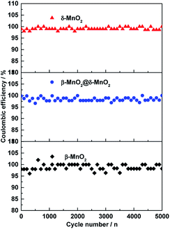 | ||
| Fig. 8 Coulombic efficiency of β-MnO2, δ-MnO2 and β-MnO2@δ-MnO2 electrodes for 5000 cycles at a current density of 1 A g−1. | ||
The Nyquist plots of the electrochemical impedance spectroscopy (EIS) of β-MnO2, δ-MnO2 and β-MnO2@δ-MnO2 electrodes are present in Fig. 9(A). All plots show semicircles at the higher frequency region and straight lines at the lower frequency region. The diameters of the semicircles in the high-frequency represent the Faradic charge transfer resistance of the redox reactions at the electrode–electrolyte interface. It can be observed from Fig. 9(A) that the charge transfer resistance of β-MnO2@δ-MnO2 is lower than that of β-MnO2 and δ-MnO2, suggesting that the charge transfer is the fastest one among these three samples. The straight lines on the EIS spectra correspond to the ion diffusion process in the bulk of the active mass in the low-frequency region. The slope (of the straight line) of β-MnO2 is larger than that of β-MnO2@δ-MnO2 and δ-MnO2, indicating that the ion diffusion resistance on β-MnO2 is the smallest among the three samples. The slope of β-MnO2@δ-MnO2 is slightly higher than that of δ-MnO2, suggesting that β-MnO2 can provide faster ion diffusion in the bulk of the active mass and faster Faradic charge transfer on the interface of electrode–electrolyte when core–shell structured β-MnO2@δ-MnO2 is formed. Fig. 9(B) shows the EIS curves of β-MnO2@δ-MnO2 before and after 5000 cycles. It can be observed that semicircles at the higher frequency region are quite similar, indicating, after 5000 cycles, the charge transfer resistance of β-MnO2@δ-MnO2 almost didn't change. The slope of β-MnO2@δ-MnO2 is slightly smaller than that of β-MnO2@δ-MnO2 after 5000 cycles, suggesting that the ion diffusion resistance on β-MnO2@δ-MnO2 after 5000 cycles only increase a little bit. The EIS results clearly show that the structure of β-MnO2@δ-MnO2 is very stable in 1 M LiOH electrolyte. The SEM image of β-MnO2@δ-MnO2 after 5000 cycles (shown in Fig. 2(D)) also confirms its structural stability.
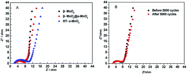 | ||
| Fig. 9 (A) Electrochemical impedance spectroscopy (EIS) curves of β-MnO2, δ-MnO2 and β-MnO2@δ-MnO2; (B) EIS curves of β-MnO2@δ-MnO2 before and after 5000 cycles. | ||
4. Conclusions
In summary, a hierarchical β-MnO2@δ-MnO2 core–shell structure with β-MnO2 nano-wires as cores and layered structure δ-MnO2 as shells were synthesized via a simple wet chemical method. Compared to δ-MnO2 and β-MnO2, β-MnO2@δ-MnO2 shows excellent cycling stability. The capacitance retention of β-MnO2@δ-MnO2 is almost unchanged with coulombic efficiency values close to 100% after 5000 cycles. It was found that the excellent cycling stability of β-MnO2@δ-MnO2 arises from synergistic effects between the core–shell structured manganese oxides with different structures/dimensions and the 1D β-MnO2 used as a stable structural supportive backbone, which could reduce the structural damage during the reversible Faradaic redox reactions occurring in MnO2. Therefore the as-prepared β-MnO2@δ-MnO2 offers a new promising cathode candidate material for alkali supercapacitors.Acknowledgements
The authors would like to thank the National Natural Science Foundation of China (51362027, 21363022, 21606050 and 51661008) for financially supporting this work.References
- A. Gambou-Bosca and D. Bélanger, Electrochim. Acta, 2016, 201, 20–29 CrossRef CAS.
- T. Wang, F. Dong and Y. X. Zhang, Mater. Lett., 2016, 171, 319–322 CrossRef CAS.
- G. He, M. Qiao, W. Li, Y. Lu, T. Zhao, R. Zou, B. Li, J. A. Darr, J. Hu, M.-M. Titirici and I. P. Parkin, Adv. Sci., 2017, 4, 1600214 CrossRef PubMed.
- M. Huang, F. Li, F. Dong, Y. X. Zhang and L. L. Zhang, J. Mater. Chem. A, 2015, 3, 21380–21423 CAS.
- S. J. Zhu, J. Q. Jia, T. Wang, D. Zhao, J. Yang, F. Dong, Z. G. Shang and Y. X. Zhang, Chem. Commun., 2015, 51, 14840–14843 RSC.
- J. Shao, X. Zhou, Q. Liu, R. Zou, W. Li, J. Yang and J. Hu, J. Mater. Chem. A, 2015, 3, 6168–6176 CAS.
- W. Li, J. Wang, G. He, L. Yu, N. Noor, Y. Sun, X. Zhou, J. Hu and I. P. Parkin, J. Mater. Chem. A, 2017, 5, 4352–4358 CAS.
- Z.-S. Wu, W. Ren, D.-W. Wang, F. Li, B. Liu and H.-M. Cheng, ACS Nano, 2010, 4, 5835–5842 CrossRef CAS PubMed.
- M. H. Alfaruqi, J. Gim, S. Kim, J. Song, D. T. Pham, J. Jo, Z. Xiu, V. Mathew and J. Kim, Electrochem. Commun., 2015, 60, 121–125 CrossRef CAS.
- S. Devaraj and N. Munichandraiah, J. Phys. Chem. C, 2008, 112, 4406–4417 CAS.
- S. Bag and C. R. Raj, J. Mater. Chem. A, 2016, 4, 8384–8394 CAS.
- A. M. Kannan, S. Bhavaraju, F. Prado, M. M. Raja and A. Manthiram, J. Electrochem. Soc., 2002, 149, A483–A492 CrossRef CAS.
- J. Cao, Q. Mao, L. Shi and Y. Qian, J. Mater. Chem., 2011, 21, 16210 RSC.
- B. Ming, J. Li, F. Kang, G. Pang, Y. Zhang, L. Chen, J. Xu and X. Wang, J. Power Sources, 2012, 198, 428–431 CrossRef CAS.
- M. Pang, G. Long, S. Jiang, Y. Ji, W. Han, B. Wang, X. Liu and Y. Xi, Electrochim. Acta, 2015, 161, 297–304 CrossRef CAS.
- J. Zhang, X. Yang, Y. He, Y. Bai, L. Kang, H. Xu, F. Shi, Z. Lei and Z.-H. Liu, J. Mater. Chem. A, 2016, 4, 9088–9096 CAS.
- J. Zhu, W. Shi, N. Xiao, X. Rui, H. Tan, X. Lu, H. H. Hng, J. Ma and Q. Yan, ACS Appl. Mater. Interfaces, 2012, 4, 2769–2774 CAS.
- T. T. Truong, Y. Liu, Y. Ren, L. Trahey and Y. Sun, ACS Nano, 2012, 6, 8067–8077 CrossRef CAS PubMed.
- S. W. Lee, B. M. Gallant, H. R. Byon, P. T. Hammond and Y. Shao-Horn, Energy Environ. Sci., 2011, 4, 1972–1985 CAS.
- G. Zhu, H. Li, L. Deng and Z.-H. Liu, Mater. Lett., 2010, 64, 1763–1765 CrossRef CAS.
- X. Zhang, X. Chang, N. Chen, K. Wang, L. Kang and Z.-h. Liu, J. Mater. Sci., 2012, 47, 999–1003 CrossRef CAS.
- Z. Jia, J. Wang, Y. Wang, B. Li, B. Wang, T. Qi and X. Wang, J. Mater. Sci. Technol., 2016, 32, 147–152 Search PubMed.
- S. Brunauer, L. S. Deming, W. E. Deming and E. Teller, J. Am. Chem. Soc., 1940, 62, 1723–1733 CrossRef CAS.
- Q. Qu, P. Zhang, B. Wang, Y. Chen, S. Tian, Y. Wu and R. Holze, J. Phys. Chem. C, 2009, 113, 14020–14027 CAS.
- K. Wang, C. Zhao, S. Min and X. Qian, Electrochim. Acta, 2015, 165, 314–322 CrossRef CAS.
- Y. Hu, J. Wang, X. Jiang, Y. Zheng and Z. Chen, Appl. Surf. Sci., 2013, 271, 193–201 CrossRef CAS.
- J. An, X. Peng, S. Xu, Z. Xu and J. Wang, RSC Adv., 2015, 5, 97080–97088 RSC.
- F. Lai, Y.-E. Miao, Y. Huang, T.-S. Chung and T. Liu, J. Phys. Chem. C, 2015, 119, 13442–13450 CAS.
- G.-R. Li, Z.-P. Feng, Y.-N. Ou, D. Wu, R. Fu and Y.-X. Tong, Langmuir, 2010, 26, 2209–2213 CrossRef CAS PubMed.
- X. Zhang, J. Ma, W. Yang, Z. Gao, J. Wang, Q. Liu, J. Liu and X. Jing, CrystEngComm, 2014, 16, 4016 RSC.
| This journal is © The Royal Society of Chemistry 2017 |

