 Open Access Article
A simple and convenient method to fabricate new types of phytic acid–metal conversion coatings with excellent anti-corrosion performance on the iron substrate†
Ru Yana,
Xiang Gaob,
Wei Hea,
Rui Guoa,
Ruonan Wua,
Zhuangzhi Zhaoa and
Houyi Ma *a
*a
aKey Laboratory of Colloid and Interface Chemistry of State Education Ministry, School of Chemistry and Chemical Engineering, Shandong University, Jinan 250100, China. E-mail: hyma@sdu.edu.cn; Fax: +86-531-88564464; Tel: +86-531-88364959
bKey Laboratory of Marine Environmental Corrosion and Bio-fouling, Institute of Oceanology, Chinese Academy of Sciences, Qingdao 266071, China
First published on 22nd August 2017
Abstract
A simple and practical method was developed to prepare a series of phytic acid (PA)–metal complex coatings on iron substrate by directly immersing the iron samples in the mixed solutions containing PA and metal ions. The key technologies of fabricating PA–metal complex coatings include: (i) anchoring of PA molecules onto the iron surface via complexation with Fe2+ ions dissolved from the iron substrate, and (ii) layer-by-layer deposition of PA–metal complexes on the PA/Fe2+ bottom layer through the bridging effect of additive metal ions. The present method was applicable to the film-forming process of a variety of metal ions, such as Zn2+, Ca2+, Co2+ and Ni2+, and the as-prepared PA–metal complex coatings were defined as PA–M conversion coatings (M = Zn2+, Ca2+, Co2+ and Ni2+ herein). Due to the strong coordination ability, PA molecules may be self-assembled on the iron surface, forming a layer of organic thin film (here defined as PA film), without the help of additive metal ions. However, the comparison between PA film and PA–M coatings shows that PA–M coatings were much thicker (over 15 μm) and denser and also possessed much stronger anti-corrosion performance compared to the PA film. The present study provides a new path for the fabrication of environmentally-friendly PA-based chemical conversion coatings and further broadens the application range of PA in metal surface pretreatment.
1. Introduction
Corrosion prevention of iron and steels has always been the focus of intensive fundamental and applied research. The corrosion of iron and steels not only brings severe damage to the national economy but also causes environmental pollution and human injury.1–3 Consequently, various anti-corrosion methods have been developed to slow the corrosion rate of steel parts or products in different corrosive environments.4–6 Among them, chemical conversion coating, i.e. a multifunctional, protective surface layer on a metal substrate that is created by chemical reaction between the metal and a chemical solution, is playing an irreplaceable role in the corrosion protection of metals as a major means for metal surface pretreatment. The two most widely used chemical conversion coatings are chromate conversion coating and phosphate conversion coating.7–11 Taking the conventional phosphate coating as an example, it is typically used as a foundation for further coatings or painting. This requires the conversion coating to provide not only the protective effect on the corrosion of metal substrate but also the strong adhesion between the paint/coating and the substrate. However, due to the high toxicity of hexavalent chromium to ecological environment and human health as well as the serious phosphorus pollution caused by the discharge of the inorganic phosphates, the development of environmentally-friendly conversion coatings as substitutes for the conversional ones has become international consensus.7,8 Several chromium- and phosphate-free alternatives, such as sol–gel coatings,12,13 conductive polymer coatings,14 ZrO2-based nano ceramic conversion coatings and rare earth-based films,7,15,16 have come up in this situation although their overall performance and durability need to be improved in comparison with those of chromium and phosphate conversion coatings.In view of the above-mentioned facts, some researchers have turned their attention to natural, nontoxic, and multifunctional compounds and tried to use them as green film-forming substances to construct environmentally-friendly chemical conversion coatings with excellent anti-corrosive performance. Because of nontoxicity, unique molecular structure and especially the strong binding affinity to some important minerals, such as iron, zinc, and calcium, phytic acid (PA) has attracted researchers' special attention in the field of metal surface treatment for a long time.7,17,18 As we know, PA is a natural, water-soluble organic compound extracted from foodstuff and contains 24 oxygen atoms, 12 hydroxyl groups and 6 phosphate carboxyl groups in its molecule. Such structure enable it to possess very strong chelating ability for many metal ions like Fe3+, Al3+, Mg2+, Cu2+, Zn2+ and Ca2+.7,18,19 It is expected that PA is able to produce a corrosion protective film through chelation with the dissolved metal ions. It is reported that PA was used as a green corrosion inhibitor to protect copper, iron and Mg–Li alloys against corrosion.17–21 Unfortunately, the PA thin films formed on the surface of Mg and Al alloy showed relatively poor anticorrosion ability when they served as protective barrier layers.22 More recently, our group has found that PA can work as an corrosion inhibitor for the iron under acidic conditions while as a film former on the iron surface under neutral conditions.18 The results showed that PA did not show the strong inhibition effectiveness in two conditions.18 Meanwhile, in what way PA molecules construct the corrosion protective film has remained unclear and controversial so far. And what is more, there have been few reports concerning the self-assembly of PA molecules on the iron surface at present.
Recently, some reports about the fabrication of functional coatings on solid substrates based on the continuous deposition of the complexes of multifunctional ligands with metal ions, such as dopa–Fe complexes,23 the complexes of tannic acid or phytic acid with Fe(III) ions,24,25 have caused our great attention. With reference to the film-forming mechanism, herein we developed a new self-assembly method of PA/Mn+ (metal ions) complexes onto the iron substrate in an aqueous solution and further used it to fabricate new PA–M chemical conversion coatings on the iron substrate. The present study and obtained results are helpful for better understanding how to design and fabricate new types of conversion coatings with the strong corrosion resistance properties.
2. Experimental section
2.1 Materials and chemical reagents
Iron plate samples (50 mm × 50 mm × 0.4 mm) were purchased from Changan Gangde Co., Ltd and the main compositions (at%) were listed in Table 1. Before the experiment, iron plate specimens were cleaned, polished with 1200 grit emery sandpapers, rinsed with ultrapure water and ethanol, and dried in flow of N2.| Element | C | Al | Si | S | Mn | Fe |
|---|---|---|---|---|---|---|
| at% | 0.70 | 0.37 | 0.14 | 0.14 | 0.30 | 98.35 |
Phytic acid (PA) aqueous solution (50 wt%) was obtained from Aldrich Ltd. Zn(NO3)2·6H2O, Ca(NO3)2·4H2O, Co(NO3)2·6H2O, Ni(NO3)2·6H2O, sodium chloride and sodium hydroxide were obtained from Sinopharm Chemical Reagent Co., Ltd. All aqueous solutions used here were prepared using ultrapure water (electrical resistivity: ∼18 MΩ cm).
2.2 Fabrication of PA-based thin films
The dilute PA solution of 5 μg L−1 was prepared by diluting 50 wt% PA solution with ultrapure water. Then pH value of the dilute PA solution was adjusted from about 1.5 to 6 by adding NaOH solution in order to meet the requirement for preparing high-quality PA film on the iron substrate. The PA solution with pH = 6 was used as the film-forming solution for the preparation of the PA thin film. An iron sample was immersed in the film-forming solution for 10 min, and then taken out from the solution, washed with ultrapure water for 2 min, followed by drying at room temperature. In this way, the PA thin film was formed on the iron substrate.For the preparation of PA–M coatings (M = Zn2+, Ca2+, Co2+ and Ni2+), a set of metal nitrate solutions of 5 mmol L−1 (specifically Zn(NO3)2, Ca(NO3)2, Co(NO3)2 and Ni(NO3)2 solutions) were prepared by dissolving appropriate amount of solid nitrate in 1 L of ultrapure water respectively. Then a series of mixed solutions of 5 μg L−1 PA and 2.5 mmol L−1 metal nitrate were prepared by mixing the same volume of 10 μg mL−1 PA solution and 5 mmol L−1 metal nitrate solution. After the pH value of each mixed solution was adjusted to 6 by using NaOH solution, the film-forming solution for preparing PA–M coatings was obtained. By following the above-mentioned film-forming procedure, the PA–M coatings (M = Zn2+, Ca2+, Co2+ and Ni2+) were directly formed on the iron substrate.
2.3 Surface analysis and characterization
The ATR-FTIR spectra of PA-based coating coated iron samples were carried out using a Bruker TENSOR 27 FTIR in wave number range of 500–4000 cm−1. The X-ray photoelectron spectroscopy (XPS) measurements were performed using a Perkin Elmer PHI 5300 system fitted with an Mg Kα X-ray source and analyzed by XPS software (XPS peak 4.1) with a reference value 284.5 eV (C–C/C–H). A field emission scanning electron microscope (FESEM) equipped with energy dispersive spectrometer (EDS) was used to investigate the surface morphologies and elemental compositions ratio of all samples. Cross-sectional SEM images were obtained to evaluate film thickness and growth mode of PA-based films. All SEM measurements were implemented in a JSM-6390LV SEM (JEOL, Japan) instrument. AFM images were obtained using a Nanoscope IIIa AFM with a fixed flexible micro cantilever under tapping mode.2.4 Electrochemical measurements
HZ-7000 and CHI 604C electrochemical workstations were used to conduct electrochemical impedance spectroscopy (EIS) and polarization curve measurements, respectively. Electrochemical tests were carried out in conventional three-electrode test cell with 3.5 wt% NaCl solution as the electrolyte solution. The untreated or treated iron samples directly worked as the working electrode, a platinum plate as the counter electrode and Ag–AgCl electrode (EEGs) as reference electrode. EIS measurement was performed with a sinusoidal wave of ±5 mV amplitude in the frequency range from 100 kHz to 50 mHz. Polarization curves were recorded by scanning the potential from cathodic side to anodic side at a slow sweep speed of 0.2 mV s−1. The electrodes were stabilized for several minutes in the electrolyte solution before tests to attain stable open-circuit potentials (OCPs).3. Results and discussion
3.1 FTIR and XPS studies of PA film and PA–M coatings
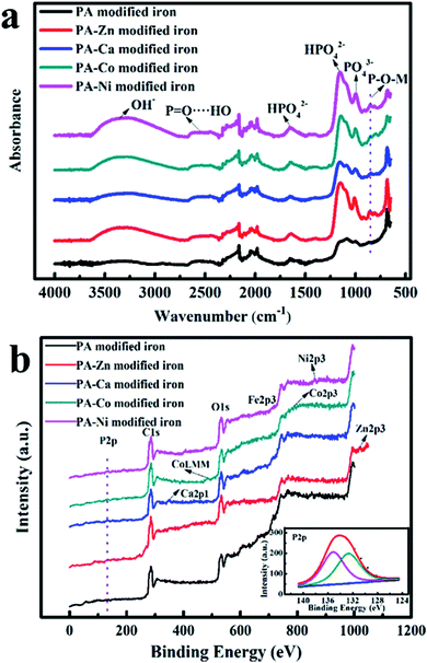
On the basis of the ATR-FTIR and XPS results, functional groups and chemical compositions of PA-based coatings were analyzed and determined. As shown in Fig. 1a, the iron plate samples coated by PA-based coatings all displayed the characteristic peaks from phytic acid molecules. The characteristic peaks at 1638 cm−1, 1153 cm−1 and 1001 cm−1 were assigned to phosphate group and phosphate hydrogen group, respectively.7 The peaks around 2500 cm−1 were related to P![[double bond, length as m-dash]](https://www.rsc.org/images/entities/char_e001.gif) O⋯HO.26 A series of broad peaks around 3300 cm−1 were attributed to hydroxyl stretching vibrations and the peak positions shifted towards low wavenumbers due to the formation of intermolecular hydrogen bonds. In particular, a series of new peaks located at 861.5 cm−1 assigned to P–O–M (M represents the metal ions that coexisted with PA) bonds emerged, which provided the direct evidences for the formation of metal phytates.27
O⋯HO.26 A series of broad peaks around 3300 cm−1 were attributed to hydroxyl stretching vibrations and the peak positions shifted towards low wavenumbers due to the formation of intermolecular hydrogen bonds. In particular, a series of new peaks located at 861.5 cm−1 assigned to P–O–M (M represents the metal ions that coexisted with PA) bonds emerged, which provided the direct evidences for the formation of metal phytates.27
For the iron modified by the PA film, P–O–M (P–O–Fe) bonds originated from the complexation of phytic molecules with the dissolved iron ions under acid condition. In addition, all peaks for the PA film modified iron were relatively weak, so we can assume that only a small amount of PA molecules were absorbed onto the surface of iron substrate and the resulting PA film was very thin.
According to the XPS spectra shown in Fig. 1b, each PA–M (M = Zn2+, Ca2+, Co2+, Ni2+) coating contained the coexisting metal ions and revealed the intense signal related to P element. This indicates that metal ions participated in the formation process for the PA–M coatings. For the iron covered with the PA film, the signal of P element was almost invisible and the signal from the iron element was the most intense (see Fig. S1†). It also shows from one side that only a few PA molecules anchored on the iron surface. According to the previous report, the Fe 2p peak at about 723.3 eV was associated with Fe2+.28 Another two peaks located at around 713 eV and 725.7 eV were assigned to Fe3+ bound to phosphate group.28,29 In addition, the inset in Fig. 1b showed that high resolution spectra of P element for the PA film-modified iron. The high resolution P 2p spectrum may be decomposed into two peaks. The peak located at 132.7 eV was corresponding to phosphate groups in phytate,30 and another peak centered at 135.0 eV was associated with phosphorus in iron polyphosphates.31 Therefore, PA film was formed through a chelation reaction between phytic molecules and dissolved iron ions, followed by the formation of intermolecular hydrogen bonds.
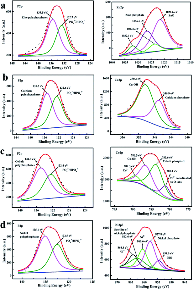
Similarly, high resolution XPS spectra of major elements (P and the coexisting metals) for different PA–M coatings (see Fig. 2) were fitted to better understand the surface compositions of PA–M coatings. The high-resolution P 2p spectra for all the PA–M coatings consisted of two main components: one peak located at higher binding energy was attributed to metal polyphosphates (135.5 eV for zinc polyphosphates, 135.3 eV for calcium polyphosphates, 134.9 eV for cobalt polyphosphates, and 135.1 eV for nickel polyphosphates); another peak centered at lower binding energy was related to phosphate groups in phytic acid molecules.30,31
The high resolution spectra of the coexisting metal elements were also analyzed. The measured high resolution Zn 2p spectrum could be fitted by four parts. One was at 1021.6 eV, and others were located at 1023.6 eV, 1026.6 eV and 1032.1 eV, respectively. The peak centered at 1021.6 eV was assigned to zinc oxide,32 other peaks were located at higher binding energies than the peak position of zinc oxide. The difference was in accordance with the formation of a zinc phosphate network that is more ionic than a zinc oxide network.33 Specifically, the binding energy value of 1023.6 eV can be compared with the corresponding BE value of 1024.1 eV, as reported for Zn(His)2 (zinc complex with histidine ligand), wherein Zn atoms were tetrahedrally surrounded by the oxygen atoms.32 Similarly, the binding energy value of 1026.6 eV can be compared with that of about 1026 eV for Zn5IP6 (Zn(II) metal complex Na3Zn5(C6H6O24P6)OH·9H2O).34 Therefore, the peaks located at 1023.6 eV, 1026.6 eV and 1032.1 eV originated from the coordination of oxygen and zinc atoms, indicating that zinc atoms were the state of coexistence of complex and oxide. The measured high resolution Ca 2p spectrum was fitted with two components: Ca 2p3/2 at 346.9 eV and Ca 2p1/2 at 350.3 eV, which were agreed well with that of hydroxyapatite (consist of two parts: apatite and hydroxyl).35,36 Therein, the Ca 2p3/2 at 346.9 eV was the characteristic of calcium ions bounded with a phosphate group. Therefore, compared with the hydroxyapatite, the PA–Ca coating consisted of Ca2+ bound to the phosphate group from phytic acid molecules and hydroxyl component from P–OH. The high resolution Co 2p spectrum was resolved into the four signals centered at 781.1 eV, 783.6 eV, 786.5 eV and 789.3 eV, respectively. The component at 781.1 eV was attributed to the characteristics of Co2+ that coordinated to O ions.37 The peak located at 783.6 eV was assigned to the presence of cobalt phosphate.38 Meanwhile, the peak centered at 786.5 eV was ascribed to the Co–OH and the peak at 789.3 eV was the satellite of Co2+.37,39 The high resolution Ni 2p3 spectrum observed was fitted with up to five components. The resolved Ni 2p3 peak located at the lowest binding energy of 854.6 eV was ascribed to the Ni in nickel oxide.40 The peak at 857.8 eV with a satellite at 862.6 eV was the characteristics of nickel phosphate.41 The remaining two peaks at higher binding energy were assigned to Ni2+.42,43 It was worth noticing that metal polyphosphates (metal phytate) were generated and supposed to be major components for all PA–M coatings. Maybe the coexisting metal oxide or hydroxide was included into the coatings.
3.2 SEM and AFM characterizations
SEM measurement was carried out to study the differences in surface morphology between the naked iron and the iron coated with PA-based coatings (Fig. 3). Meanwhile, cross-sectional images were also given to observe the changes of film thickness under the conditions of existence of PA and different metal ions (see Fig. 4 and S4†). It was observed that there were some small holes on the surface of the iron sample covered with the PA film. This phenomenon was also observed from a mica sheet modified with the PA film (Fig. S5†) by AFM. It is roughly determined that the PA film was very thin with a thickness of 0.56 μm. The PA-based coatings became denser with the help of coexisting metal ions, as shown in Fig. 3c–f. Therein, a large number of spherical particles appeared on the surface of the iron sample covered with the PA–Ca coating compared to the naked iron. It is inferred that the lamellar structure based on calcium phytate was firstly formed on the iron substrate, which can provide massive hydroxyl groups and induce spherical particles to grow on its surface. This situation is very similar to the formation process of polydopamine-assisted hydroxyapatite.44 At last the lamellar structure was fully and uniformly covered by the spherical particles, as indicated by Fig. S2.† In addition, EDS elemental analysis and mapping were performed for all the PA-based coatings. Each metal element corresponding to the PA–M coating was uniformly dispersed into the coating within a relatively wide range (see the insets in Fig. 3c–f). EDS elemental analyses showed that, in contrast with EDS spectrum of the PA film, the signal of P element significantly increased in intensity but that of Fe element from the metal substrate greatly reduced after the iron surface was coated with the PA–M coatings, especially in the case of PA–Zn coating (See Fig. S3†). It is obvious that PA–M coatings are much thicker and denser than the PA film so that the iron signal from the substrate is strongly blocked.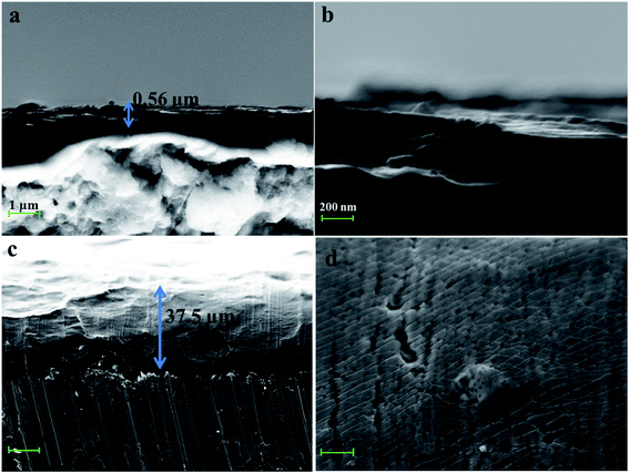 | ||
| Fig. 4 Cross-sectional SEM images of the iron samples coated with the PA film (a and b) and the PA–Zn coating (c and d). | ||
The cross-sectional SEM images of PA–M coatings further confirmed the above inference (see Fig. 4). The presence of coexisting metal ions in the film-forming solutions greatly increased the thickness of PA-based coatings, without question. All PA–M coatings were over 15 μm thick, 30 times more than the thickness of PA film. Therein, the thickness of PA–Zn coating was about 37.5 μm. Moreover, the cross-sectional topography for the PA film was quite different from that of PA–M coatings. For the PA film, whole layer structure was an integrated structure; but for every PA–M coating, the coating was constructed in layer-by-layer mode. Metal ions acted as the bridging or crosslinking agent, greatly promoting the growth of the PA–M coating in three dimensional directions.
Based on above SEM observations, it is concluded that the PA film is thin and porous compared to the PA–M coatings. It is possible that corrosive ions readily penetrate the PA film and cause the corrosion of metal substrate. By contrast, when PA coexisted with metal ions (Zn2+, Ca2+, Co2+ and Ni2+ herein), metal ions served as crosslinking agents to connect more PA molecules, thereby making the PA–M coatings become denser and thicker. As-fabricated PA–M coatings are expected to have the better corrosion resistance.
AFM measurements were performed to evaluate the differences in surface roughness between the naked iron and the iron coated by PA-based coatings, as shown in Fig. 5. Based on roughness analysis, the root-mean-square (RMS) roughness values showed obvious changes after the iron surface was covered by the PA-based coatings. For the naked iron, the roughness value of RMS was 4.40 nm. After being covered by PA-based coatings, the RMS roughness values became larger at different levels (e.g. 6.43 nm for PA film, 11.2 nm for PA–Zn coating, 5.99 nm for PA–Ca coating, 8.38 nm for PA–Co coating and 5.56 nm for PA–Ni coating). The increase of roughness values is very beneficial for enhancing adhesion strength between the PA-based conversion layers and top coatings in painting system.
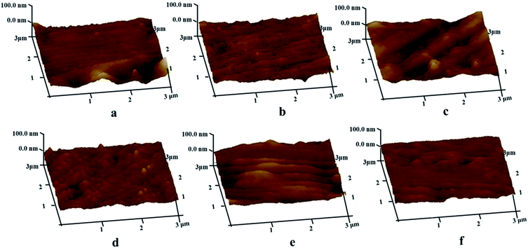 | ||
| Fig. 5 AFM images of the naked iron (a) and the iron coated with the PA film (b), PA–Zn coating (c), PA–Ca coating (d), PA–Co coating (e) and PA–Ni coating (f). | ||
3.3 Anticorrosion performances
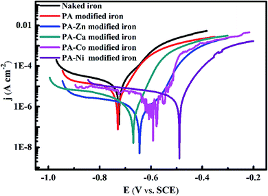 | ||
| Fig. 6 Polarization curves of the naked iron, PA film modified iron and PA–M (M = Zn2+, Ca2+, Co2+, Ni2+) coatings modified iron electrodes in 3.5 wt% NaCl solution. | ||
Corrosion potential (Ecorr), corrosion current density (icorr) and other electrochemical parameters involved in the corrosion process, such as anodic Tafel slope (ba), were acquired by using the Tafel extrapolation method. Meanwhile, protection efficiencies (PE, expressed as η) of all PA-based coatings were calculated according to the following equation:
| Samples | Ecorr (mV) | ba (mV dec−1) | Icorr (A cm−2) | η (%) |
|---|---|---|---|---|
| Naked iron | −725 | 83.25 | 1.820 × 10⁻⁵ | — |
| PA modified iron | −729 | 63.87 | 1.120 × 10⁻⁶ | 38.46 |
| PA–Zn modified iron | −645 | 54.92 | 8.156 × 10⁻⁷ | 95.52 |
| PA–Ca modified iron | −669 | 49.21 | 1.056 × 10⁻⁶ | 94.19 |
| PA–Co modified iron | −592 | 42.18 | 2.443 × 10⁻⁶ | 86.57 |
| PA–Ni modified iron | −489 | 62.35 | 5.026 × 10⁻⁶ | 72.38 |
In view of the similar impedance behavior, impedance behavior of the naked iron and the PA film modified iron can be modeled by two equivalent circuits with the same form but different physical meaning shown in Fig. 8a. In this circuit, Rs represents the solution resistance, Rct charge-transfer resistance, and CPEdl is a constant phase element (CPE) that is used as the substitute for pure capacitor to fit more exactly the depressed capacitive loop. For the naked iron, the CPE may stand for the double-layer capacitance at the iron/solution interface. However, for the PA film modified iron, the CPE// contained the contributions from the capacitance of PA film and the double-layer capacitance at the iron/solution interface.
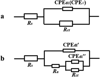 | ||
| Fig. 8 Equivalent circuits used for fitting impedance behavior of the iron electrodes before (a) and after being coated with the PA film (a) and PA–M coatings (b). | ||
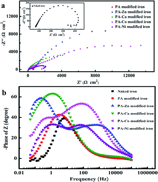
When coexisting metal ions participated in the film-forming process, the great changes of the impedance behavior were observed from the corresponding Nyquist and Bode spectra. The Nyquist spectra for the PA–M coating modified iron electrodes show a large capacitive loop in complex plane and the size of capacitive loop is dependent on the coexisting metal ion in the film-forming solution. Bode impedance spectra indicate more clearly that the corrosion process of iron substrate involved two time constant for each PA–M coating modified electrode, including PA–Ca modified electrode, although its time constant in high frequency seemed not obvious. As compared with the naked iron electrode, the new time constant appeared in high frequency region, which was associated with the relaxation process of the film resistance and the double-layer capacitance at the defective sites. The impedance behavior of PA–M coating modified electrode can be interpreted with the equivalent circuit shown in Fig. 8b. In this circuit, Rs and Rct have the same physical meaning as what they represent in the circuit shown in Fig. 8a. Ra stands for the film resistance, CPE′dl is corresponding to coating capacitance and CPE′′dl is associated with double-layer capacitance at the iron/solution interface.
On the basis of the two equivalent circuits, the values of elements were required by fitting the impedance data and listed in Table 3. Meanwhile, the protection efficiency (PE) of each PA-based coating was calculated according to the following formula:
| Samples | Rs (Ω cm2) | Ra (Ω cm2) | CPE′dl | Rct (Ω cm2) | CPE′′dl (CPEdl CPE//) | η (%) | ||
|---|---|---|---|---|---|---|---|---|
| Y0 (Ω−1 cm−2 sn) | n | Y0 (Ω−1 cm−2 sn) | n | |||||
| Naked iron | 72.05 | — | — | — | 385.7 | 2.797 × 10⁻³ | 0.84 | |
| PA modified iron | 60.61 | — | — | — | 645.3 | 2.293 × 10⁻³ | 0.90 | 40.46 |
| PA–Zn modified iron | 52.67 | 1010.7 | 7.124 × 10⁻⁴ | 0.58 | 25![[thin space (1/6-em)]](https://www.rsc.org/images/entities/char_2009.gif) 300 300 |
1.275 × 10⁻³ | 0.85 | 98.54 |
| PA–Ca modified iron | 59.40 | 106.9 | 8.845 × 10⁻⁴ | 0.85 | 8452.8 | 2.802 × 10⁻³ | 0.82 | 95.49 |
| PA–Co modified iron | 72.47 | 2734.3 | 3.645 × 10⁻⁴ | 0.71 | 12![[thin space (1/6-em)]](https://www.rsc.org/images/entities/char_2009.gif) 265 265 |
2.049 × 10⁻³ | 0.78 | 97.37 |
| PA–Ni modified iron | 71.79 | 996.1 | 1.549 × 10⁻³ | 0.60 | 2400.2 | 2.275 × 10⁻³ | 0.79 | 88.64 |
3.4 Film-forming mechanism for the PA–M coatings
PA molecule, as a multifunctional ligand containing 6 phosphate carboxyl groups and 12 hydroxyl groups, can be anchored onto the iron surface in the manner of self-assembly based on the complexation effect. In more specific terms, a PA molecule is able to complex the Fe2+ ions dissolved from the iron substrate in aqueous solution and further adsorbs onto the iron surface. Meanwhile, intermolecular hydrogen bonds are starting to form. In this way, thin and porous PA film can be directly formed on the iron surface.When PA and metal ions coexist in the same solution, the film-forming mechanism of PA on the iron substrate is greatly changed. Fig. 9 shows a schematic diagram for the formation of PA–M (M = Zn2+, Ca2+, Co2+, Ni2+) coatings on the iron substrate. In the mixed solution of PA and metal ions, PA molecules may complex the coexisting metal ions to form the metal phytate complex with the lamellar structure. Once an iron sample (e.g. iron plate) is immersed in the film-forming solution, some PA molecules will firstly anchor on the iron substrate in the pattern of self-assembly mentioned above, forming PA bottom layer, and then more PA molecules will deposit on the bottom layer through the chelating reaction between phytic molecules and the designated metal ions. Finally, the thicker and denser PA–M coatings, mainly composed of metal phytate complexes with the lamellar structure, spontaneously form on the iron substrate through the layer-by-layer growth. At the same time, metal oxides or hydroxides may be included into the PA–M coating due to the existence of oxygen in the film-forming solution. The present film-forming mechanism is very applicable to illustrating the formation of PA–Zn, PA–Co and PA–Ni coatings and partially suitable for describing the formation of PA–Ca coating since there are some spherical particles on the lamellar structure.
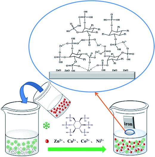 | ||
| Fig. 9 Schematic diagrams for the formation of the PA–M (M = Zn2+, Ca2+, Co2+, Ni2+) coatings on the iron substrates. | ||
Seeing that the as-prepared PA–M coatings possess the excellent anticorrosion performance and the newly developed film-forming method is simple, convenient, and applicable to many metal ions, the present study opens a new path to fabricate environmentally-friendly chemical conversion coatings.
4. Conclusion
A series of PA–M (M = Zn2+, Ca2+, Co2+ and Ni2+) chemical conversion coatings with good anticorrosion performances were directly formed on the iron substrate by taking full advantage of the strong binding affinity of PA to the iron surface and the layer-by-layer growth of PA–M complexes on the PA primer through the bridging effect of metal ions (M) in the film-forming solution. As compared with thin and porous PA film, the PA–M coatings are denser and thicker, which gives them excellent anticorrosion properties, especially for the PA–Zn coating. Because the film former, PA, is natural nontoxic compound and the film-forming process of PA–M coatings is simple and environment-friendly, the new PA–M conversion coatings are expected to work as the substitutes for chromate and phosphate coatings and will find wide application in the surface pretreatment of iron and steels.Conflicts of interest
There are no conflicts to declare.Acknowledgements
The authors are grateful for the support from the National Natural Science Foundation of China (21373129 and 21673130).References
- C. Wang, F. Jiang and F. Wang, Corros. Sci., 2004, 46, 75–89 CrossRef CAS.
- T. T. Isimjan, T. Wang and S. Rohani, Chem. Eng. J., 2012, 210, 182–187 CrossRef CAS.
- X. Li, R. Kind, X. Yuan, I. Wölbern and W. Hanka, Nature, 2004, 427, 827–829 CrossRef CAS PubMed.
- M. Hino, K. Murakami, A. Saijo and T. Kanadani, Mater. Trans., 2008, 49, 924–930 CrossRef CAS.
- M. Yadav, D. Behera, S. Kumar and P. Yadav, Chem. Eng. Commun., 2014, 202, 303–315 CrossRef.
- Y. Feng and Y. F. Cheng, Chem. Eng. J., 2017, 315, 537–551 CrossRef CAS.
- H. Shi, E.-H. Han, F. Liu and S. Kallip, Appl. Surf. Sci., 2013, 280, 325–331 CrossRef CAS.
- W. Zhou, D. Shan, E.-H. Han and W. Ke, Corros. Sci., 2008, 50, 329–337 CrossRef CAS.
- H. Huo, Y. Li and F. Wang, Corros. Sci., 2004, 46, 1467–1477 CrossRef CAS.
- G. Y. Li, J. S. Lian, L. Y. Niu, Z. H. Jiang and Q. Jiang, Surf. Coat. Technol., 2006, 201, 1814–1820 CrossRef CAS.
- D. Weng, R. Wang and G. Zhang, Met. Finish., 1998, 96, 54–57 CrossRef CAS.
- M. L. Zheludkevich, R. Serra, M. F. Montemor, I. M. M. Salvado and M. G. S. Ferreira, Surf. Coat. Technol., 2006, 200, 3084–3094 CrossRef CAS.
- H. Shi, F. Liu and E. Han, Mater. Chem. Phys., 2010, 124, 291–297 CrossRef CAS.
- K. Kamaraj, V. Karpakam, S. Syed Azim and S. Sathiyanarayanan, Synth. Met., 2012, 162, 536–542 CrossRef CAS.
- M. Dabala, L. Armelao, A. Buchberger and I. Calliari, Appl. Surf. Sci., 2001, 172, 312–322 CrossRef CAS.
- M. J. Paterson, D. G. McCulloch, P. J. K. Paterson and B. Ben-Nissan, Thin Solid Films, 1997, 311, 196–206 CrossRef CAS.
- Y. Chen, S. Zhao, B. Liu, M. Chen, J. Mao, H. He, Y. Zhao, N. Huang and G. Wan, ACS Appl. Mater. Interfaces, 2014, 6, 19531–19543 CAS.
- X. Gao, C. Zhao, H. Lu, F. Gao and H. Ma, Electrochim. Acta, 2014, 150, 188–196 CrossRef CAS.
- X. Cui, Q. Li, Y. Li, F. Wang, G. Jin and M. Ding, Appl. Surf. Sci., 2008, 255, 2098–2103 CrossRef CAS.
- L. Gao, C. Zhang, M. Zhang, X. Huang and X. Jiang, J. Alloys Compd., 2009, 485, 789–793 CrossRef CAS.
- C. Hao, R.-H. Yin, Z.-Y. Wan, Q.-J. Xu and G.-D. Zhou, Corros. Sci., 2008, 50, 3527–3533 CrossRef CAS.
- F. Pan, X. Yang and D. Zhang, Appl. Surf. Sci., 2009, 255, 8363–8371 CrossRef CAS.
- M. J. Harrington, A. Masic, N. Holten-Andersen, J. H. Waite and P. Fratzl, Science, 2010, 328, 216–220 CrossRef CAS PubMed.
- H. Ejima, J. J. Richardson, K. Liang, J. P. Best, M. P. van Koeverden, G. K. Such, J. Cui and F. Caruso, Science, 2013, 341, 154–157 CrossRef CAS PubMed.
- L. Li, G. Zhang and Z. Su, Angew. Chem., 2016, 128, 9239–9242 CrossRef.
- J. G. Speight, Lange's handbook of chemistry, McGraw-Hill, New York, 2005 Search PubMed.
- X. Chen, G. Zeng, T. Gao, Z. Jin, Y. Zhang, H. Yuan and D. Xiao, Electrochem. Commun., 2017, 74, 42–47 CrossRef CAS.
- T. Ghoshal, T. Maity, J. F. Godsell, S. Roy and M. A. Morris, Adv. Mater., 2012, 24, 2390–2397 CrossRef CAS PubMed.
- R.-R. Zhao, B.-Y. Lan, H.-Y. Chen and G.-Z. Ma, Ionics, 2012, 18, 873–879 CrossRef CAS.
- J. Zhang, Z. Zhao, Z. Xia and L. Dai, Nat. Nanotechnol., 2015, 10, 444–452 CrossRef CAS PubMed.
- F. Mangolini, A. Rossi and N. D. Spencer, J. Phys. Chem. C, 2012, 116, 5614–5627 CAS.
- P. Gerstel, R. C. Hoffmann, P. Lipowsky, L. P. H. Jeurgens, J. Bill and F. Aldinger, Chem. Mater., 2006, 18, 179–186 CrossRef CAS.
- R. K. Brow, J. Non-Cryst. Solids, 1996, 194, 267–273 CrossRef CAS.
- U. Rodriguesfilho, S. Vazjr, M. Felicissimo, M. Scarpellini, D. Cardoso, R. Vinhas, R. Landers, J. Schneider, B. McGarvey and M. Andersen, J. Inorg. Biochem., 2005, 99, 1973–1982 CrossRef CAS PubMed.
- F. Balas, J. Pérez-Pariente and M. Vallet-Regí, J. Biomed. Mater. Res., Part A, 2003, 66, 364–375 CrossRef CAS PubMed.
- J. L. Ong, C. A. Hoppe, H. L. Cardenas, R. Cavin, D. L. Carnes, A. Sogal and G. N. Raikar, J. Biomed. Mater. Res., 1998, 39, 176–183 CrossRef CAS PubMed.
- B. Cao, G. M. Veith, J. C. Neuefeind, R. R. Adzic and P. G. Khalifah, J. Am. Chem. Soc., 2013, 135, 19186–19192 CrossRef CAS PubMed.
- R. K. Meruva and M. E. Meyerhoff, Anal. Chem., 1996, 68, 2022–2026 CrossRef CAS PubMed.
- N. Fradette and B. Marsan, J. Electrochem. Soc., 1998, 145, 2320–2327 CrossRef CAS.
- S. Chen, L. Brown, M. Levendorf, W. Cai, S. Ju, J. Edgeworth, X. Li, C. W. Magnuson, A. Velamakanni, R. D. Piner, J. Kang, J. Park and R. S. Ruoff, ACS Nano, 2011, 5, 1321–1327 CrossRef CAS PubMed.
- M. Ledendecker, S. Krick Calderón, C. Papp, H.-P. Steinrück, M. Antonietti and M. Shalom, Angew. Chem., Int. Ed., 2015, 54, 12361–12365 CrossRef CAS PubMed.
- M. C. Biesinger, B. P. Payne, A. P. Grosvenor, L. W. M. Lau, A. R. Gerson and R. S. C. Smart, Appl. Surf. Sci., 2011, 257, 2717–2730 CrossRef CAS.
- Y. Wang, C. Xie, D. Liu, X. Huang, J. Huo and S. Wang, ACS Appl. Mater. Interfaces, 2016, 8, 18652–18657 CAS.
- J. Ryu, S. H. Ku, H. Lee and C. B. Park, Adv. Funct. Mater., 2010, 20, 2132–2139 CrossRef CAS.
Footnote |
| † Electronic supplementary information (ESI) available: Additional experimental data involved with XPS, SEM, EDS and AFM measurements of both PA and PA–M coatings were presented. See DOI: 10.1039/c7ra06186b |
| This journal is © The Royal Society of Chemistry 2017 |

