 Open Access Article
Cr2O3/carbon nanosheet composite with enhanced performance for lithium ion batteries
Zhiqin Cao * and
Chengyang Zuo
School of Materials Engineering, Pan Zhihua University, Pan Zhihua 617000, China. E-mail: 591828998@qq.com
First published on 17th August 2017
Abstract
A Cr2O3/carbon nanosheet composite is directly synthesized by solution combustion synthesis using chromium nitrate as the chromium source and glucose as the carbon source. The Cr2O3/carbon nanosheet composite serving as an anode material for lithium ion batteries has been studied, exhibiting higher cycling and rate performance than pure Cr2O3. The carbon in the composite not only inhibits the growth of Cr2O3 particles, but also improves the electrical conductivity of Cr2O3 and buffers the volume change during the lithium ion insertion/extraction process, which enhances the electrochemical performance.
1. Introduction
Due to their superior properties such as high energy density, long cycle life, no memory effect and environmental friendliness, lithium ion batteries (LIBs) have been widely used in portable electronic devices (e.g., laptops and mobile phones), hybrid vehicles and clean energy storage.1–4 In order to search for new electrode materials with high-capacity and rate capability for LIBs, several transition metal oxides have been intensively studied, such as Co3O4, Fe3O4, NiO, MnO2 and SnO2.5–11 The theoretical specific capacities of metal oxides usually range from 700 to 1000 mA h g−1 between 0.001 and 3.0 V vs. Li/Li+, which is much higher than that of commercial graphite (370 mA h g−1). Among various transition metal oxides that are prospective electrodes for LIBs, Cr2O3 has attracted considerable attention due to its low cost, high theoretical capacity (∼1058 mA h g−1) and relatively low lithium insertion potential (1.085 V).12–15 Unfortunately, the practical application of Cr2O3 in LIBs is still hindered with problems of low electrical conductivity and severe volume change during cycles, which result in a rapid capacity fading and the end of cycle life.16,17 Many strategies have been used to solve these problems, including the preparation of nano-materials, mesoporous materials, and carbon composites.18–22 Among these strategies, carbon composites has been widely studied since carbon could not only cushion the stress from volume change of active materials and maintain the structure integrity of electrode during cycles, but also prevent the agglomeration metal oxide nanoparticles. Ya Fu et al.23 have prepared Cr2O3/carbon nanocomposites by directly carbonizing the glycine–CrCl3 gel precursor and the prepared Cr2O3 nanoparticles were embedded in carbon sheets which exhibit superior cycling and rate performances than pure Cr2O3 as lithium-ion battery anode materials. Syed Mustansar Abbas et al.24 synthesized chromium oxide (Cr2O3) nanoparticles and carbon nanotubes (CNTs) by in situ chemical co-precipitation method and this study offers a possibility of improving lithium ion storage of Cr2O3 nanoparticles by using CNTs buffering matrix. Ling-Yan Jiang et al.25 synthesized Cr2O3–C composite nanospheres by a facile soft-template assisted method and indicated that the carbon in the composite can improve the lithium storage capacity dramatically. Therefore, Cr2O3 and carbon composite can be expected to show enhanced performance for LIBs.Herein, this work describe a novel strategy for the preparation of Cr2O3/carbon nanosheet composite by solution combustion synthesis (SCS). Solution combustion synthesis is typically a redox based reaction that takes place in a homogeneous aqueous solution of oxidizing (e.g., metal nitrates) and reducing agents (fuels).26–29 In this work, the oxidizing agent is chromium nitrate and the reducing agents is glycine. In order to induce the carbon into the products, the glucose is used as carbon source. This method is very facile and effective for preparing Cr2O3/carbon nanosheet composite in high yield. On the basis of the crystal structure, morphology and the comparative of the Cr2O3 is also presented and discussed. The electrochemical properties of the as-prepared Cr2O3/carbon nanosheet composite as LIBs anode materials are also investigated.
2. Experimental
2.1 Synthesis
The products were prepared by solution combustion synthesis. All the chemicals (analytical reagent grade) used for solution combustion synthesis were commercially purchased. The carbon/Cr2O3 nanosheet composite was prepared by using chromium nitrate [Cr(NO3)3·9H2O], glycine [NH2CH2COOH] and glucose [C6H12O·H2O] as starting materials. Briefly, chromium nitrate (10 g), glycine (7.5 g) and glucose (5 g) were dissolved in 150 mL deionized water under stirring to obtain a redox mixture. The mixture was filled in a 500 mL glass, and was heated in air on an electrical furnace whose temperature could be controlled. And the temperature was controlled at 300 °C. It took about 10 minutes to take place the redox reaction. The pure Cr2O3 particles were also prepared for comparison. Briefly, chromium nitrate (10 g) and glycine (7.5 g) were dissolved in 150 mL deionized water under stirring to obtain a redox mixture. The experimental phenomenon were similar with the previous reports.13,30 All of the products were directly synthesized by the solution combustion synthesis without any further process.2.2 Characterization
The products were analyzed by X-ray diffractometer using Cu-Kα radiation (λ = 0.1542 nm, Rigaku D/max-RB12). The X-ray photoelectron spectroscopy (XPS) analysis was carried out using AXIS Ultra DLD spectrometer equipped with an Al Kα X-ray source and electrostatic hemispherical electron analyzer. The differential scanning calorimetry (DSC) were performed from ambient temperature to 800 °C in air at a heating rate of 10 °C min−1 using a TGA/DSC type instrument (MettlerToledo, Switzerland). The morphology and particle size of products were observed by scanning electron microscopy (SEM, JSM-5600) and transmission electron microscopy (TEM, Tecnai G2 F30 S-TWIN).2.3 Electrochemical measurements
Electrochemical of the electrode material was performed using Cr2O3/carbon nanosheet composite as a working electrode and lithium metal as a counter electrode. The working electrode was fabricated by mixing the active materials with acetylene black (AB) and a binder, poly(vinylidene fluoride) (PVDF), at weight ratios of 40![[thin space (1/6-em)]](https://www.rsc.org/images/entities/char_2009.gif) :
:![[thin space (1/6-em)]](https://www.rsc.org/images/entities/char_2009.gif) 40
40![[thin space (1/6-em)]](https://www.rsc.org/images/entities/char_2009.gif) :
:![[thin space (1/6-em)]](https://www.rsc.org/images/entities/char_2009.gif) 20. The mixture was dispersed in the NMP solvent to form slurry and uniformly pasted on the Cu foil with a blade. A non-aqueous solution of 1 M LiPF6 was dissolved in a 1
20. The mixture was dispersed in the NMP solvent to form slurry and uniformly pasted on the Cu foil with a blade. A non-aqueous solution of 1 M LiPF6 was dissolved in a 1![[thin space (1/6-em)]](https://www.rsc.org/images/entities/char_2009.gif) :
:![[thin space (1/6-em)]](https://www.rsc.org/images/entities/char_2009.gif) 1 (volume/volume) mixture of ethylene carbonate (EC) and dimethyl carbonate (DMC). The cells were charged and discharged on a land test system (Land CT2001A) in a voltage window of 0.01–3 V at 25 °C. For the high rate testing, the charge/discharge current gradually increased from 0.1 to 0.2, 0.5, 1, 2, 5 and 10C, and then decreased to 1C and 0.1C, step by step. Electrochemical impedance spectroscopy (EIS) were tested by an electrochemistry workstation (CHI618D) at a scanning rate of 0.5 mV s−1. EIS were measured by applying an AC voltage of 10 mV amplitude over the frequency range between 100 kHz and 10 mHz at room temperature.
1 (volume/volume) mixture of ethylene carbonate (EC) and dimethyl carbonate (DMC). The cells were charged and discharged on a land test system (Land CT2001A) in a voltage window of 0.01–3 V at 25 °C. For the high rate testing, the charge/discharge current gradually increased from 0.1 to 0.2, 0.5, 1, 2, 5 and 10C, and then decreased to 1C and 0.1C, step by step. Electrochemical impedance spectroscopy (EIS) were tested by an electrochemistry workstation (CHI618D) at a scanning rate of 0.5 mV s−1. EIS were measured by applying an AC voltage of 10 mV amplitude over the frequency range between 100 kHz and 10 mHz at room temperature.
3. Results and discussion
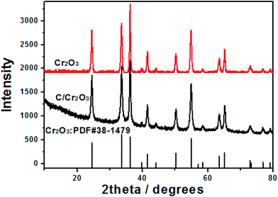
Fig. 1 shows the XRD patterns of products prepared by SCS. All the peaks can be index the eskolaite structure (JCPDS no. 38-1479) with the lattice parameters: a = 4.959 Å, b = 4.959 Å, c = 13.594 Å. No impurity phase is detected either in Cr2O3 and Cr2O3/carbon, indicating the carbon in the Cr2O3/carbon composite is amorphous. According to the Scherrer's formula:31,32 β = kλ/L![[thin space (1/6-em)]](https://www.rsc.org/images/entities/char_2009.gif) cos
cos![[thin space (1/6-em)]](https://www.rsc.org/images/entities/char_2009.gif) θ, where λ is the X-ray wavelength (k = 0.154 nm), L is the average crystallite size, k is the shape factor, β is the full width at half maximum, and θ is Bragg angle in degree, the average crystalline size of Cr2O3 and Cr2O3/carbon composites sample is calculated to be about 23.4 and 19.0 nm, respectively. The results imply the carbon in the composite would hinder the particle to growth. Many researches have been indicated that the carbon in the products prepared by SCS can inhibit the growth of nano-oxides.33,34 The composition of the Cr2O3/carbon is further characterized by XPS and the results are shown in Fig. 2. In the survey scan XPS spectrum of the Cr2O3/carbon composites, the peaks of Cr 2p, O 1s, N 1s and C 1s are observed, implying the existence of Cr, O, N and C elements in the composite. The weight content of the Cr, O, N and C elements evaluated by the XPS are 25.2%, 44.1%, 3.96% and 26.8%, respectively. In Fig. 2b, the peaks located at 586.4 and 576.9 eV are assigned to Cr 2p1/2 and Cr 2p3/2, respectively.35 In Fig. 2c, the deconvoluted C 1s peaks at 288.9, 287.6, 286.5, 284.7 eV are correspond to the O–C
θ, where λ is the X-ray wavelength (k = 0.154 nm), L is the average crystallite size, k is the shape factor, β is the full width at half maximum, and θ is Bragg angle in degree, the average crystalline size of Cr2O3 and Cr2O3/carbon composites sample is calculated to be about 23.4 and 19.0 nm, respectively. The results imply the carbon in the composite would hinder the particle to growth. Many researches have been indicated that the carbon in the products prepared by SCS can inhibit the growth of nano-oxides.33,34 The composition of the Cr2O3/carbon is further characterized by XPS and the results are shown in Fig. 2. In the survey scan XPS spectrum of the Cr2O3/carbon composites, the peaks of Cr 2p, O 1s, N 1s and C 1s are observed, implying the existence of Cr, O, N and C elements in the composite. The weight content of the Cr, O, N and C elements evaluated by the XPS are 25.2%, 44.1%, 3.96% and 26.8%, respectively. In Fig. 2b, the peaks located at 586.4 and 576.9 eV are assigned to Cr 2p1/2 and Cr 2p3/2, respectively.35 In Fig. 2c, the deconvoluted C 1s peaks at 288.9, 287.6, 286.5, 284.7 eV are correspond to the O–C![[double bond, length as m-dash]](https://www.rsc.org/images/entities/char_e001.gif) O, C
O, C![[double bond, length as m-dash]](https://www.rsc.org/images/entities/char_e001.gif) C, C–O and C–C groups, respectively.36 In Fig. 2d, the N 1s peak could be divided into four peaks located at 401, 399, 398.0 eV, which correspond to the –NH–, –NO– and –N
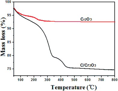
C, C–O and C–C groups, respectively.36 In Fig. 2d, the N 1s peak could be divided into four peaks located at 401, 399, 398.0 eV, which correspond to the –NH–, –NO– and –N![[double bond, length as m-dash]](https://www.rsc.org/images/entities/char_e001.gif) groups, respectively.37,38 Research has confirmed that the N-doped carbon composite was favorable to improvement of the electrochemical performance.39 The content of carbon in the products were further calculated by TG curves. The experiments were carried out from room temperature to 800 °C at a heating rate of 10 °C min−1 in air. As shown in Fig. 3, the content of carbon is ∼7.2% for Cr2O3 and ∼27.6% for Cr2O3/carbon, respectively, which was consistent with the XPS results. The carbon in the Cr2O3 is due to the decomposed of some glycine. The addition carbon in the Cr2O3/carbon is attribute to the carbon derived form the glucose.
groups, respectively.37,38 Research has confirmed that the N-doped carbon composite was favorable to improvement of the electrochemical performance.39 The content of carbon in the products were further calculated by TG curves. The experiments were carried out from room temperature to 800 °C at a heating rate of 10 °C min−1 in air. As shown in Fig. 3, the content of carbon is ∼7.2% for Cr2O3 and ∼27.6% for Cr2O3/carbon, respectively, which was consistent with the XPS results. The carbon in the Cr2O3 is due to the decomposed of some glycine. The addition carbon in the Cr2O3/carbon is attribute to the carbon derived form the glucose.
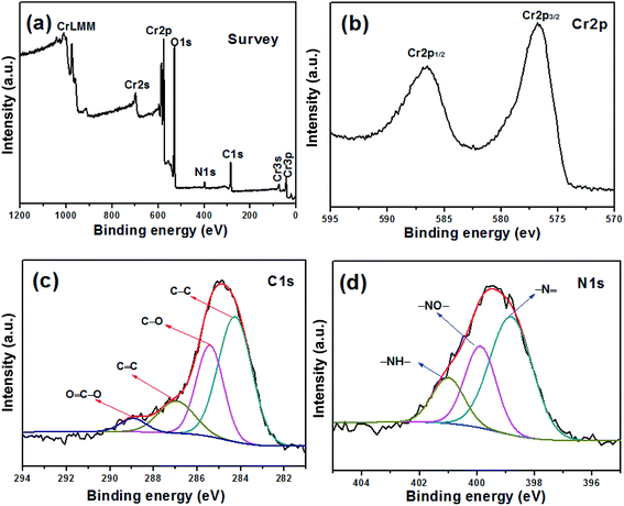 | ||
| Fig. 2 XPS spectra of Cr2O3/carbon: (a) survey scan, (b–d) high resolution spectra of Cr 2p, C 1s and N 1s. | ||
Fig. 4a shows the SEM images of the Cr2O3/carbon composite. It is obvious that the products has sheet structure. The sheet structure is attribute to the glucose which can lead to the formation of nanosheet microstructure.40 The energy dispersive spectra (EDS) elemental mapping of the selected area obtained on SEM results (Fig. 4b–d) clearly reveal that a uniform distribution Cr, O and C elements. The magnification of the SEM shown in Fig. 4e exhibits some pores in the sheet which is formed by the gases liberated during the reactions.
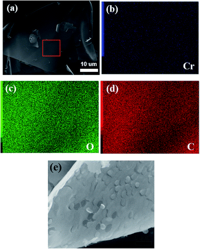 | ||
| Fig. 4 (a) SEM micrographics of Cr2O3/carbon; (b–d) EDS element mapping data of precursor; (e) SEM micrographics of precursor. | ||
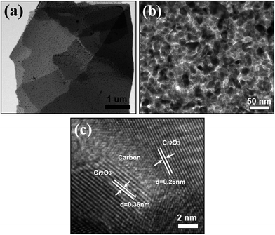
The Cr2O3/carbon composite was further characterized by TEM. As shown in Fig. 5a and b, the Cr2O3 particles with size less than 20 nm was uniformly embedded on the carbon sheet. In the HRTEM image (Fig. 5c, the typical lattice fringe spacing are measured to be 0.36 and 0.26 nm, corresponding to the (012) and (104) crystal plane of Cr2O3. The carbon sheet form interconnected and continuous network with Cr2O3 particles, which is a special feature of the composites. This is essential to maintain the internal electronic contact of particles during the charging and discharging process, especially for insulating electrode materials with high capacity.
The charge/discharge curves of the Cr2O3/carbon for the first three cycles obtained at the current density of 100 mA h g−1 in the voltage window of 0.01–3.0 V (vs. Li/Li+) are presented in Fig. 6. It can be seen that the first and second specific discharge capacity of the mesoporous Cr2O3 nanoparticles is as high as 1680 mA h g−1 and 1042 mA h g−1, respectively. The first discharge capacity is larger than the theoretical capacity of 1058 mA h g−1, which can be due to the SEI (solid electrolyte interphase) layer forming by the decomposed electrolyte at low voltage and further lithium insertion via interfacial charging at the metal/Li2O interfaces.41,42 Moreover, there is a plateau at 0.7 V only for the initial discharge capacities. It is assigned to the irreversible reductive decomposition of the electrolyte forming the SEI layer. The overlap of the second and the third discharge curves shows that the Cr2O3 sheet structure electrode is stable during these cycles.
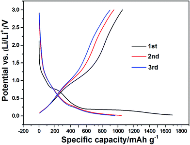 | ||
| Fig. 6 The first three charge/discharge curves of Cr2O3/carbon at a current density of 100 mA g−1, in the 0.01–3.0 V voltage range. | ||
Fig. 7a shows the cycle performance of Cr2O3 and Cr2O3/carbon evaluated at 0.1C. Without the carbon as substrate, the capacity of Cr2O3 decreased rapidly to 500 mA h g−1 after 20 cycles. On the contrary, Cr2O3/carbon shows better cycling stability and higher specific capacity retention than Cr2O3. Even after 55 cycles, the reversible capacity of Cr2O3/carbon is stable and still retains at 710 mA h g−1. Fig. 7b shows the cycle performance of Cr2O3/carbon evaluated at 0.5C and 1C. The reversible capacity of Cr2O3/carbon is 410 mA h g−1 and 360 mA h g−1, respectively.
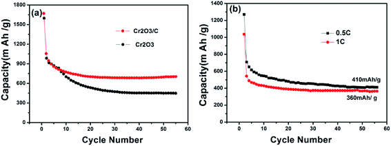 | ||
| Fig. 7 (a) Cycle performance of Cr2O3 and Cr2O3/carbon at 0.1C rate; (b) cycle performances of Cr2O3/carbon at 0.5C rate and 1C. | ||
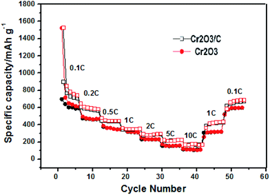
As expected, the cycle performance of the Cr2O3 and Cr2O3/carbon with varied current rates are revealed in Fig. 8. The Cr2O3/carbon delivers a reversible capacity of 705, 560, 439, 358, 290, 215 and 169 mA h g−1 at a current rate of 0.1, 0.2, 0.5, 1, 2, 5 and 10C, respectively. When the current rate is returns to 0.1C, and Cr2O3/carbon still a reversible capacity of 694 mA h g−1 is obtained. In contrast, the only delivers a reversible capacity of 582, 441, 331, 305, 225, 155 and 121 mA h g−1 at a current rate of 0.1, 0.2, 0.5, 1, 2, 5 and 10C respectively. It is obvious that the Cr2O3/carbon exhibits better rate capability than Cr2O3. It is believed that the carbon in the Cr2O3/carbon nanosheet composite favorable to improve the electrical conductivity of between Cr2O3 nanoparticles which would proved in EIS analysis and finally improve the cycle and rate performances.
Fig. 9 compares the Nyquist plots of Cr2O3 and Cr2O3/carbon after 5 cycles CV testing. As shown in Fig. 9, both electrodes comprise a depressed semicircle in the high frequency and a sloped straight line in the low frequency. Researches indicated that the diameter of the semicircle is related to the charge transfer process occurring at the electrode and electrolyte interface, and is in direct proportion to the impedance including electrolyte resistance (Re), surface film resistance (Rsf) and charge transfer resistance (Rct).43 The inclined line low frequency corresponds to the Warburg impedance (W) associated with the lithium ion diffusion process inside the electrode, and the straight line is in inverse proportion to the Warburg impedance.44 It is obvious in Fig. 9 that the diameter of the semicircle for the Cr2O3/carbon is smaller than that of Cr2O3, indicating that the carbon in the composites can improve the electrical conductivity and charge transfer at interface of Cr2O3 nanoparticles. In addition, the Cr2O3/carbon shows larger slope than Cr2O3 in the low frequency, which suggests that the ion diffusion ability of Cr2O3/carbon is better. The electrochemical impedance spectroscopy results can infer the Cr2O3/carbon exhibits lower impedance (including Re, Rsf, Rct and W) at the electrode/electrolyte interface and inside the electrode, validating that the introduced carbon to the Cr2O3 can improve charge transfer and lithium ion diffusion ability, and thereby resulted in the enhanced of the electrochemical performances in LIBs. This is due to that the carbon in the composites not only buffer the strain from the volume variation of Cr2O3 during lithiation and delithiation process, and also inhibit the aggregation of Cr2O3 during charge/discharge process.
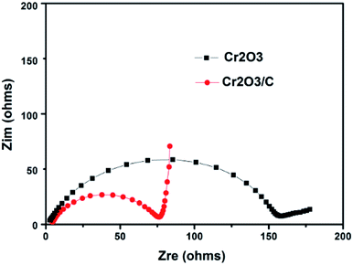 | ||
| Fig. 9 Nyquist plots of Cr2O3 and Cr2O3/carbon electrodes after 5 cycles CV testing. Frequency range between 100 kHz and 10 mHz at room temperature. | ||
4. Conclusion
Cr2O3/carbon nanosheet composite is successfully synthesized by solution combustion synthesis using chromium nitrate, glycine and glucose as raw materials. As anode materials for LIBs, the Cr2O3/carbon nanosheet composite shows superior cycling and rate performance compared with pure Cr2O3. The carbon and the special sheet structure play an important role on inhibiting the growth of Cr2O3 particles, improving the electrical conductivity of Cr2O3 and acting as a favorable buffer to the volume change during the lithium ion insertion/extraction process, leading to an enhanced electrochemical performance. This facile strategy can offer an effective technique for the preparation of other transition metal oxides and carbon nanosheet composites for energy storage devices.Acknowledgements
This work was supported by the Science Foundation Program of Panzhihua (2014CY-G-26-2).References
- W. Yue, S. Tao, J. Fu, Z. Gao and Y. Ren, Carbon, 2013, 65, 97–104 CrossRef CAS.
- C. T. Cherian, T. Sundaramurthy, M. Kalaivani, P. Ragupathy, P. S. Kumar and V. Thavasi, et al., J. Mater. Chem., 2012, 22, 12198 RSC.
- M. Armand and J. M. Tarascon, Nature, 2008, 451, 652–657 CrossRef CAS PubMed.
- J. Zhang, Y. Sun, Y. Yao, T. Huang and A. Yu, J. Power Sources, 2013, 222, 59–65 CrossRef CAS.
- N. Q. Zhao, S. Wu, C. N. He, Z. Y. Wang, C. S. Shi and E. Z. Liu, et al., Carbon, 2013, 57, 130–138 CrossRef CAS.
- S. Zhu, J. Li, X. Deng, C. He, E. Liu and F. He, et al., Adv. Funct. Mater., 2017, 27, 1605017 CrossRef.
- L. Zhan, H. Chen, J. Fang, S. Wang, L. X. Ding and Z. Lia, et al., Electrochim. Acta, 2016, 209, 192–200 CrossRef CAS.
- S. H. Jiang, W. B. Yue, Z. Q. Gao, Y. Ren, H. Ma and X. H. Zhao, et al., J. Mater. Sci., 2013, 48, 3870–3876 CrossRef CAS.
- L. Wen, X. Qin, W. Meng, N. Cao and Z. Song, Mater. Sci. Eng., B, 2016, 213, 63–68 CrossRef CAS.
- W. B. Yue, Z. Z. Lin, S. H. Jiang and X. J. Yang, J. Mater. Chem., 2012, 22, 16318–16323 RSC.
- X. C. Liu, J. Y. Piao, D. S. Bin, T. Q. Zhang, S. Y. Duan and Z. X. Wu, et al., Chem. Commun., 2017, 53, 2846–2849 RSC.
- S. Grugeon, S. Laruelle, L. Dupont, F. Chevallier, P. L. Taberna and P. Simon, et al., Chem. Mater., 2005, 17, 5041–5047 CrossRef CAS.
- Z. Cao, M. Qin, B. Jia, L. Zhang, Q. Wan and M. Wang, et al., Electrochim. Acta, 2014, 139, 76–81 CrossRef CAS.
- J. Hu, H. Li and X. J. Huang, Electrochem. Solid-State Lett., 2005, 8, A66–A69 CrossRef CAS.
- L. Dupont, S. Grugeon, S. Laruelle and J. M. Tarascon, J. Power Sources, 2007, 164, 839–848 CrossRef CAS.
- C. Nethravathi, B. Viswanath, J. Michael and M. Rajamath, Carbon, 2012, 50, 4839–4846 CrossRef CAS.
- W. B. Yue, S. H. Jiang, W. J. Huang, Z. Q. Gao, J. Li and Y. Ren, J. Mater. Chem. A, 2013, 1, 6928–6933 CAS.
- J. Hu, H. Li, X. J. Huang and L. Q. Chen, Solid State Ionics, 2006, 177, 2791–2799 CrossRef CAS.
- X. Zhao, Q. C. Zhuang, S. D. Xu, Y. X. Xu, Y. L. Shi and X. Z. Zhang, J. Electrochem. Soc., 2015, 162, A1156–A1162 CrossRef CAS.
- L. Dupont, S. Laruelle, S. Grugeon, C. Dickinson, W. Z. Zhou and J. M. Tarascon, J. Power Sources, 2008, 175, 502–509 CrossRef CAS.
- B. K. Guo, M. F. Chi, X. G. Sun and S. Dai, J. Power Sources, 2012, 205, 495–499 CrossRef CAS.
- H. Liu, X. W. Du, X. R. Xing, G. X. Wang and S. Z. Qiao, Chem. Commun., 2012, 48, 865–867 RSC.
- Y. Fu, H. Gu, X. Yan, J. Liu, Y. Wang and J. Huang, et al., Chem. Eng. J., 2015, 277, 186–193 CrossRef CAS.
- S. M. Abbas, N. Ahmad, Ata-ur-Rehman, U. A. Rana, S. U.-D. Khan and S. Hussain, Electrochim. Acta, 2016, 212, 260–269 CrossRef CAS.
- L. Y. Jiang, S. Xin, X. L. Wu, H. Li, Y. G. Guo and L. J. Wan, Mater. Chem., 2010, 20, 7565–7569 RSC.
- S. T. Aruna and A. S. Mukasyan, Curr. Opin. Solid State Mater. Sci., 2008, 12, 44–50 CrossRef CAS.
- K. C. Patil, S. T. Aruna and T. Mimani, Curr. Opin. Solid State Mater. Sci., 2003, 6, 507–512 CrossRef.
- A. Cross, S. Roslyakov, K. V. Manukyan, S. Rouvimov, A. S. Rogachev and D. Kovalev, et al., J. Phys. Chem. C, 2014, 118, 26191–26198 CAS.
- A. S. Mukasyan, P. Epstein and P. Dinka, Proc. Combust. Inst., 2007, 31, 1789–1795 CrossRef.
- Z. Cao, M. Qin, C. Zuo, B. Jia, Y. Liu, Y. Gu and X. Qu, J. Nanopart. Res., 2015, 17, 72 CrossRef.
- T. Hu, X. Sun, H. T. Sun, M. P. Yu, F. Y. Lu and C. S. Liu, et al., Carbon, 2013, 51, 322–326 CrossRef CAS.
- W. B. Yue, S. Yang, Y. Ren and X. J. Yang, Electrochim. Acta, 2013, 92, 412–420 CrossRef CAS.
- Z. Cao, M. Qin, A. Chu, M. Huang, H. Wu and X. Qu, Mater. Res. Bull., 2014, 52, 74–77 CrossRef CAS.
- A. Chu, M. Qin, Rafi-ud-din, B. Jia, H. Lu and X. Qu, J. Am. Ceram. Soc., 2012, 95, 2510–2515 CrossRef CAS.
- J. T. Li, V. Maurice, J. Swiatowska-Mrowiecka, A. Seyeux, S. Zanna and L. Klein, et al., Electrochim. Acta, 2009, 54, 3700–3707 CrossRef CAS.
- S. Yang, W. B. Yue, J. Zhu, Y. Ren and X. J. Yang, Adv. Funct. Mater., 2013, 23, 3570–3576 CrossRef CAS.
- H. Gu, S. B. Rapole, J. Sharma, Y. Huang, D. Cao and H. A. Colorado, et al., RSC Adv., 2012, 2, 11007–11018 RSC.
- C. W. Tsai, M. Tu, C. J. Chen, T. F. Hung, R. S. Liu and W. R. Liu, et al., RSC Adv., 2011, 1, 1349–1357 RSC.
- G. Lu, S. Qiu, J. Liu, X. Wang, C. He and Y. J. Bai, Electrochim. Acta, 2014, 117, 230–238 CrossRef CAS.
- J. Ge, H. Ding and X. Xue, Angew. Chem., Int. Ed., 2012, 51, 6205–6208 CrossRef CAS PubMed.
- P. Balaya, H. Li, L. Kienle and L. Maier, Adv. Funct. Mater., 2003, 13, 621–625 CrossRef CAS.
- J. Jamnik and J. Maier, Phys. Chem. Chem. Phys., 2003, 5, 5215–5220 RSC.
- M. S. Wang and L. Z. Fan, J. Power Sources, 2013, 244, 570–574 CrossRef CAS.
- D. Vladikova and Z. Stoynov, J. Electroanal. Chem., 2004, 572, 377–387 CrossRef CAS.
| This journal is © The Royal Society of Chemistry 2017 |

