 Open Access Article
Highly thermally conductive and electrically insulating polymer nanocomposites with boron nitride nanosheet/ionic liquid complexes†
Takuya Morishita * and
Naoko Takahashi
Toyota Central R&D Labs., Inc., Nagakute, Aichi 480-1192, Japan. E-mail: morishita-t@mosk.tytlabs.co.jp
First published on 21st July 2017
Abstract
Highly thermally conductive and electrically insulating polymer materials are eagerly anticipated for thermal management of various applications including next-generation power electronic devices. Herein, boron nitride nanosheet (BNNS)/ionic liquid (IL)/polymer composites with high thermal conductivity (TC) and high electrical insulation were fabricated. BNNSs were exfoliated and noncovalently functionalized with ILs by one-step route using liquid-phase exfoliation of hexagonal boron nitrides in ILs. ILs improved exfoliation by physical adsorption on BNNS surfaces, forming highly soluble few-layered BNNS/IL complexes with high yields. The use of 1-butyl-3-methylimidazolium hexafluorophosphate ([bmim][PF6]) gave sufficient amounts of BNNS/[bmim][PF6] complexes for fabrication of BNNS/IL/polymer composites. Then BNNS/[bmim][PF6]/poly(methyl methacrylate) (PMMA) composite films were prepared using a simple wet-process, significantly enhancing both through-plane and in-plane TCs. The through-plane and in-plane TCs of the BNNS/[bmim][PF6]/PMMA composite films containing 50 wt% (≈34 vol%) BNNS reached approx. 5.4 W m−1 K−1 and approx. 7.3 W m−1 K−1, respectively. The through-plane TC is superior to those of previously reported BNNS/thermoplastic (TP) polymer composites with similar BNNS loadings. This high through-plane TC derives from randomly dispersed BNNSs and good affinity between PMMA and [bmim][PF6] on the BNNS surface. The optimum functionalization ratio (FR, [bmim][PF6]/BNNS mass ratio) found for enhancing the TC represents a balance of increased compatibility of BNNS/PMMA and a decrease of TC caused by extra amorphous [bmim][PF6]. Furthermore, the combination of IL and polymer matrix species is important. The through-plane TC of BNNS/[bmim][PF6]/polybutylene terephthalate (PBT) composite films containing 50 wt% BNNS was extremely high (approx. 5.8 W m−1 K−1), although that of BNNS/[bmim][PF6]/polycarbonate (PC) composite films was very low (approx. 1.2 W m−1 K−1) because of the lower affinity of [bmim][PF6] with PC. Moreover, the volume resistivity of the BNNS/[bmim][PF6]/TP polymer composites was improved compared with that of h-BN/TP polymer composites. The BNNS/IL/polymer composites are extremely promising for various applications requiring highly TC and electrical insulation.
1. Introduction
Boron nitride nanosheet (BNNS), a 2D nanomaterial consisting of B atoms and N atoms, is a structural analogue of graphene.1–4 For use in various applications, BNNS has attracted increasing interest because it has extremely high thermal conductivity (TC, 300–2000 W m−1 K−1),2–4 high electrical insulation,2,3 good mechanical properties,2,3,5 high heat resistance,1,3,6 high chemical resistance,1,3,6 and whiteness. Especially, the nanosheets' high TC and electrically insulating properties are extremely attractive for fabricating electrically insulating materials with high heat transfer properties. Producing insulating polymeric materials that dissipate heat highly efficiently is crucially important for miniaturization, high performance, and high reliability of various applications including next generation power electronic devices, electric machinery, and communication equipment.7,8 Anisotropic nanocarbons such as carbon nanotubes and graphenes also exhibit high TC;9 therefore, the addition and dispersion of nanocarbons into polymer matrices increased the TCs of the polymers.7–11 However, nanocarbons have high electrical conductivity. For that reason, the addition of even small quantities of nanocarbons into polymer matrices increases electrical conductivity,11,12 and hence, they are unavailable for highly electrically insulating materials requiring high TC (>3 W m−1 K−1). Therefore, for the applications described above, BNNS is an extremely attractive candidate. Nevertheless, producing large quantities of BNNSs is crucially important for these applications. Currently, chemical vapor deposition (CVD) methods13,14 and liquid-phase exfoliation of bulk hexagonal boron nitrides (h-BNs) in selected solvents2,3,15–20 are popular for preparing BNNSs. CVD processing is effective for synthesizing large-area BNNSs on a metal substrate,13,14 but this method requires the transfer of BNNSs from the substrate to an appropriate substrate or solvent. Actually, liquid-phase exfoliation of bulk h-BNs is attractive because it is extremely versatile and applicable to widely various environments,2,3,15–20 as in the case of exfoliation of graphites into graphenes.21–24 However, these wet approaches for exfoliating h-BNs usually involve strong and/or extended sonication15–17,20 leading to greatly decreased lateral sizes, or the use of toxic, strong acids.18,19 Therefore, as a milder liquid-phase exfoliation method, we recently reported that h-BNs were exfoliated into BNNSs in ionic liquids (ILs) under weak sonication.25 ILs are environmentally friendly alternatives to volatile organic solvents and strong acids, and ILs show physical adsorption on BNNS surfaces. This physical adsorption is expected to improve affinity not only with solvents but also with polymer matrices to give BNNS/polymer composites with high TC and electrical insulation.As a polymer matrix for a filler/polymer composite, thermoplastic (TP) polymer recently has attracted growing interest compared with thermoset (TS) polymer26 because of its good molding processability, the ability to reform a part after consolidation, high recycling potential of the composites, and high impact resistance. Actually, TS polymers have been widely used for filler/polymer composites with high TCs; many studies have described improvement of TCs of BNNS/TS polymer composites27–33 in comparison to BNNS/TP polymer composites19,27,34–37 because increasing the TCs of BNNS/TS polymer composites is generally much easier than increasing those of BNNS/TP polymer composites (Table S1†).27 In general, wettability of BNNSs with TP polymers is lower than that with TS polymers. The uncured TS polymer monomers can give easier wetting on BNNS surfaces than TP polymers. Low wettability between BNNSs and a TP polymer matrix engenders higher thermal resistance at the interface by increased phonon scattering, and lower dispersibility of BNNSs in a TP polymer matrix. Moreover, although increasing the through-plane TC is more important than doing so for in-plane TC for the thermal management of most applications, the through-plane TCs of previously reported BNNS/TP polymer composites were generally much lower than the in-plane TCs (Table S1†) because of high interfacial thermal resistance and BNNS orientation along the plane in polymer matrices. For improving both through-plane and in-plane TC of BNNS/TP polymer composites, dispersing BNNS randomly in the matrices and increasing affinity between BNNS surfaces and TP polymer matrices are necessary. Covalent functionalization of BNNS surfaces or edges38,39 increased solubility in solvents and matrices, but it engenders formation of defects on the surfaces and reduction of the lateral sizes, which degrades the physical properties. In the case of nanocarbon/polymer composites,40–42 noncovalent functionalization of nanocarbons was effective for increasing dispersibility in the polymer matrices without damaging the nanocarbon surface structure. Similarly, noncovalent functionalization of BNNSs is expected to be effective to improve their dispersibility without damaging the BNNS surface. Actually, noncovalent functionalization of BNNS with superacid improved the dispersibility in polymer matrices.19 However, the superacid is moisture-sensitive and the acidity is stronger than pure sulfuric acid. Therefore, during BNNS production using superacids, the use of large quantities of water is necessary to remove free superacid from the BNNS, thereby producing huge amounts of acidic wastewater.
For this study, as a much milder, much simpler and more environmentally friendly method, BNNS was exfoliated and noncovalently functionalized with ILs by one-step liquid-phase exfoliation. The obtained noncovalently functionalized BNNSs (BNNS/IL complexes) were used to fabricate BNNS/TP polymer composites, giving significant enhancement of both through-plane and in-plane TCs. Moreover, the optimum functionalization ratio and appropriate combinations of IL and polymer matrix species were found for additional enhancement of TC values.
2. Experimental
2.1. Materials
h-BNs (UHP-1K, 99.9 wt% BN purity, 2.27 g cm−3 density, ∼24 μm mean secondary particle size, ∼4.0 μm mean lateral size of platelet; Showa Denko K.K., Japan) were used and dried under vacuum at 80 °C for 12 h before use. The mean secondary particle size and mean lateral size of platelet of the h-BN were estimated as average values using scanning electron microscopy (SEM) (N = 20). 1-Butyl-3-methylimidazolium bis(trifluoromethylsulfonyl)imide ([bmim][Tf2N]) (≥98% purity, 1.44 g cm−3 density) was purchased from Sigma-Aldrich Corp. (USA). Also, 1-butyl-3-methylimidazolium hexafluorophosphate ([bmim][PF6]) (≥99% purity, 1.38 g cm−3 density) was obtained from Kanto Chemical Co. Inc. (Japan). Poly(methyl methacrylate) (PMMA, grade G, 1.19 g cm−3 density) was purchased from Kuraray Co. Ltd., Japan. Polycarbonate (PC, E-2000, 1.20 g cm−3 density) was purchased from Mitsubishi Engineering-Plastics Corp., Japan. Polybutylene terephthalate (PBT, Duranex-2002, 1.31 g cm−3 density) was obtained from WinTech Polymer Ltd., Japan.2.2. Characterization
High-resolution transmission electron microscopy (HRTEM) images were obtained with instruments (Titan 80-300; FEI or JEM-2100F; JEOL) operating at 200 kV. HRTEM samples were prepared by dispersing the BNNS/IL complexes in IPA under brief bath-sonication and dropping of the resulting dispersions onto microgrids. SEM images for morphologies of BNNS/IL/PMMA composites were observed using an instrument (SU-3500; Hitachi High-Technologies Corp.). For SEM measurements, frozen fracture surfaces of the films (approx. 0.3 mm thickness) of BNNS/IL/PMMA composites were prepared. The frozen fracture surfaces of the films were coated with Pt under pure argon by sputtering (E-1045 ion sputter; Hitachi High-Technologies Corp.). X-ray photoelectron spectroscopy (XPS) data were collected using a spectrometer (Quantera SXM; Ulvac Phi Inc.) with a monochromated Al-Kα (1486.6 eV). Experimental energy shifts due to charge up were corrected relative to the C 1s peak at 284.6 eV (C–C bond). X-ray powder diffraction (XRD) patterns were recorded at a scan rate of 50° min−1 with the Cu-Kα (1.542 Å) line using a multipurpose XRD system (Ultima IV; Rigaku Corp.). Powder samples were loaded onto XRD glass plates. Thermogravimetric analysis (TGA) measurements were performed (plus TG8120; Rigaku-Thermo). Samples were held at 100 °C for 30 min under N2 flow of 500 mL min−1 and were heated to 600 °C at 10 °C min−1. The TC (κ) (W K−1 m−1) was calculated from the thermal diffusivity (α) (m2 s−1) as κ = αρc, where ρ stands for the density (kg m−3) and c signifies the specific heat capacity (J K−1 kg−1) of composites. The density was measured using a water displacement method. The specific heat capacity was ascertained from differential scanning calorimetry (DSC) measurements taken using a calorimeter (DSC 7020; Seiko Instruments Inc.). The through-plane thermal diffusivity of each composite film (10 mm × 10 mm; approx. 0.3 mm thickness) was measured at room temperature using a laser flash technique with a laser flash apparatus (LFA447 Nanoflash; Netzsch Inc.). The in-plane thermal diffusivity of the in-plane direction for each composite film (10 mm × 10 mm; approx. 0.3 mm thickness) was measured at room temperature with a thermo-wave analyzer (TA3; Bethel Co. Ltd.) under periodic laser heating. The average of three measurements was regarded as the thermal diffusivity. The volume resistivity of each composite film (50 mm × 50 mm; approx. 0.3 mm thickness) was measured using a high-resistance meter (Agilent 4339B; Agilent Technologies Inc.) equipped with a resistivity cell (16008B; Agilent) with main electrode size of 26 mm. The operating load was 5 kgf; 1000 V potential was applied to the film. The volume resistivity was measured after 1000 V potential application to the film for 20 s. The average of four measurements was regarded as volume resistivity.2.3. Typical procedure for the preparation of BNNS/IL complexes
After 75 mL of IL was added to a round-bottomed flask containing dried h-BN (375 mg), the mixture was subjected to bath-sonication using an ultrasonic cleaner (B-220, 125 W; Branson Ultrasonics Corp.) for 8 h. The resulting dispersion was centrifuged at 3000 rpm for 20 min, giving BNNS/IL supernatant. The supernatant was subjected to vacuum filtration through a preweighted 0.1 μm membrane filter and was then washed with acetone. BNNS/IL complex was obtained after drying under vacuum at 80 °C for 12 h. The BNNS/IL complexes were measured using TGA. The amount of BNNS in the BNNS/IL complex was estimated using the resulting weight loss corresponding to IL. The yields were calculated using y = 100 × MBNNS/Mh-BN, where MBNNS is the weight of BNNS and Mh-BN is the weight of the h-BN.2.4. Preparation of BNNS/[bmim][PF6]/PMMA composite films (BNNS content, 2 wt%)
First, 62.8 mg of BNNS/[bmim][PF6] complex, consisting of 60.0 mg of BNNS and 2.8 mg of [bmim][PF6], was mixed with 2.0 g of acetone and bath-sonicated for 20 min. The obtained BNNS/[bmim][PF6]/acetone solution was mixed with a PMMA/acetone (3.0 g/8.0 g) solution under bath-sonication for 30 min. The resulting BNNS/[bmim][PF6]/PMMA/acetone solution was spread on a glass plate. Then acetone was naturally volatilized for at least 24 h. BNNS/[bmim][PF6]/PMMA (BNNS content, 2 wt% ≈ 1.1 vol%) composite films with approx. 0.3 mm thickness were obtained after further drying at 50 °C for 12 h under vacuum to remove the residual acetone.2.5. Preparation of BNNS/[bmim][PF6]/PMMA composite films (BNNS content, 50 wt%)
After 157.1 mg of BNNS/[bmim][PF6] complex, consisting of 150 mg of BNNS and 7.1 mg of [bmim][PF6] was added to 1.0 g of acetone, the mixture was bath-sonicated for 20 min, and subsequently mixed with PMMA/acetone (142.9 mg/1.0 g) solution under bath-sonication for 30 min. The resulting BNNS/[bmim][PF6]/PMMA/acetone solution was spread on a glass plate. The acetone was naturally volatilized for at least 24 h. After further drying at 50 °C for 12 h under vacuum to remove the residual acetone, BNNS/[bmim][PF6]/PMMA (BNNS content, 50 wt% ≈ 34 vol%) composite films with approx. 0.3 mm thickness were obtained.2.6. Preparation of BNNS/[bmim][PF6]/PBT composite films (BNNS content, 50 wt%)
After 157.1 mg of BNNS/[bmim][PF6] complex, consisting of 150 mg of BNNS and 7.1 mg of [bmim][PF6], was added to 1.0 g of 1,1,1,3,3,3-hexafluoro-2-propanol (HFIP), the mixture was bath-sonicated for 20 min, and subsequently mixed with PBT/HFIP (142.9 mg/2.0 g) solution under bath-sonication for 30 min. The obtained BNNS/[bmim][PF6]/PBT/HFIP solution was spread on a glass plate. Then HFIP was naturally volatilized for at least 24 h. BNNS/[bmim][PF6]/PBT (BNNS content, 50 wt% ≈ 37 vol%) composite films with approx. 0.3 mm thickness were obtained after further drying at 50 °C for 12 h under vacuum to remove the residual HFIP.3. Results and discussion
3.1. Preparation and evaluation of BNNS/IL complexes
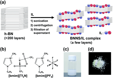
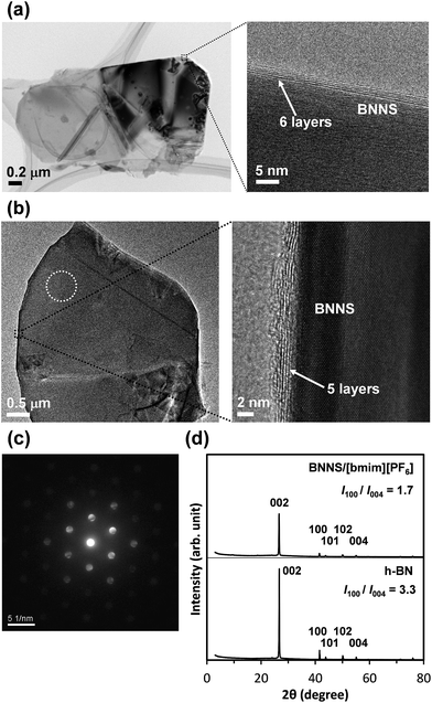
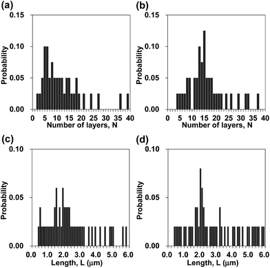
Fig. 1a presents a schematic of preparation of BNNS/IL complexes by exfoliation and noncovalent functionalization of h-BN with ILs. The [bmim][Tf2N] and [bmim][PF6] (Fig. 1b) were used as ILs for exfoliation of h-BNs. For this study, large amounts of h-BNs (375 mg) and ILs (75 mL) were used for exfoliation and noncovalent functionalization to obtain sufficient quantities (>∼75 mg) of BNNS/IL complexes for fabrication and evaluation of BNNS/IL/polymer composite films. First, h-BNs were exfoliated in ILs under bath-sonication, giving initial dispersions. Then, after centrifugation (3000 rpm, 20 min) of the initial dispersions, BNNS/[bmim][Tf2N] dispersion and BNNS/[bmim][PF6] dispersion (Fig. 1c) were obtained by collecting the supernatants. BNNS/[bmim][Tf2N] complex and BNNS/[bmim][PF6] complex (Fig. 1d) were obtained after filtration, washing, and drying of the BNNS/IL dispersions.Fig. 2a and b respectively depict HRTEM images of the obtained BNNS/[bmim][Tf2N] complex and BNNS/[bmim][PF6] complex. The layers of the BNNSs were counted by their distinguishable curled edges, which were visible in HRTEM images.2 The HRTEM images of BNNS edges of BNNS/[bmim][Tf2N] complexes and BNNS/[bmim][PF6] complexes clearly showed their few-layers-thick nature (Fig. 2a, b and S1†). Thickness distributions of the BNNS/IL complexes (Fig. 3a and b) revealed that BNNS/[bmim][Tf2N] complexes consisted mainly of fewer than 20 layers (Fig. 3a, the average number of layers: 12.1). The numbers of layers of BNNS/[bmim][PF6] complexes were predominantly fewer than 25 layers (Fig. 3b; 15.9 average number of layers). Moreover, the BNNS/[bmim][Tf2N] complexes were thinner than the BNNS/[bmim][PF6] complexes. The BNNS lattice of BNNS/[bmim][PF6] complex (Fig. 3d; approx. 2.9 μm average lattice size) was larger than that of BNNS/[bmim][Tf2N] complexes (Fig. 3c; approx. 2.3 μm average lattice size). [bmim][PF6] is a better solvent for solubilizing BNNSs than [bmim][Tf2N] as described later. Therefore, even after centrifugation at the same condition, [bmim][PF6] solubilized thicker and larger BNNSs than [bmim][Tf2N]. Better BNNS dispersion in [bmim][PF6] is regarded as resulting from higher affinity of [bmim][PF6] with BNNS under sonication. In addition, the selected area electron diffraction (SAED) pattern (Fig. 2c) revealed that BNNS/[bmim][PF6] complex had high-crystallinity hexagonal BN structures. XRD patterns of the BNNS/[bmim][PF6] complexes (Fig. 2d) showed sharp BN (002) and (004) peaks at 2θ values of ∼26.6° and ∼55.0°, respectively, demonstrating its high-crystallinity BN structure. The (002) and (004) peak intensities were weaker than those of pristine h-BNs, probably because of thinner BNNS layers than those of pristine h-BN. The XRD (002) and (004) peak intensities for BNNS/[bmim][Tf2N] complex (Fig. S2†) were even weaker than those for BNNS/[bmim][PF6] complex because of its thinner BNNS layer structure. In addition, the BNNS/[bmim][PF6] complex and BNNS/[bmim][Tf2N] complex showed much lower intensity (I) ratios between (100) and (004) planes (I100/I004) than those of h-BN (Fig. 2d and S2†), which is consistent with previously reported results.43,44 Because BNNS/IL complexes were very thin, the (002) crystal faces of BNNS/IL complexes were more readily oriented along the plane of the XRD glass plate and were more selectively exposed on the plate than those of h-BN.
Table 1 presents properties of BNNS/IL complexes prepared using different sonication conditions. After sonication and centrifugation of 375 mg of h-BNs in 75 mL of each IL, the concentrations (solubilities) of BNNSs in [bmim][Tf2N] and [bmim][PF6] were, respectively, approx. 0.30 mg mL−1 and approx. 1.09 mg mL−1 (Table 1, 1a and 2a). The [bmim][PF6] afforded much higher BNNS concentration than [bmim][Tf2N], which demonstrates that anion species played an important role in improving the BNNS concentrations. The BNNS concentrations also depended on the volume of ILs used for sonication experiments. The concentrations of BNNSs in [bmim][Tf2N] and [bmim][PF6] (Table 1, 1a and 2a) were lower than those in the case of smaller scale using 150 mg of h-BNs in 30 mL of ILs (Table 1, 1b and 2b). However, prolonged sonication (from 8 h to 16 h) increased the BNNS concentration in each IL (Table 1, 1c and 2c). The sonic energy input to the sample is known to be sensitive to various conditions such as the volume of dispersion, the water level, the exact position in the bath, and vessel shape.22 For this study, each exfoliation experiment had the same initial h-BN concentration (5 mg mL−1), almost equal water level, and exact position in the bath. Therefore, increasing the volume of BNNS/IL dispersion (the dispersion height) decreased the sonic energy input to the h-BN in IL solution, leading to large decreases of the BNNS concentrations.
| Code | IL | Vol.a (mL) | Timeb (h) | Conc.c (mg mL−1) | The number of layersd | FRe | Yieldf (%) |
|---|---|---|---|---|---|---|---|
| a Volume of IL (initial concentration of the starting material h-BN in IL: 5 mg mL−1).b Time of bath-sonication.c Average BNNS concentration in the supernatant calculated using the weight of BNNS estimated from the weight of the obtained BNNS/IL complex and the TGA weight loss corresponding to IL.d Average value of the number of layers measured by HRTEM (N = 40).e IL/BNNS mass ratio of BNNS/IL complex.f Average yield of BNNS. | |||||||
| 1a | [bmim][Tf2N] | 75 | 8 | 0.30 | 12.1 | 0.056 | 5.7 |
| 1b | [bmim][Tf2N] | 30 | 8 | 0.46 | 6.0 | 0.100 | 9.0 |
| 1c | [bmim][Tf2N] | 75 | 16 | 0.40 | — | 0.075 | 7.8 |
| 2a | [bmim][PF6] | 75 | 8 | 1.09 | 15.9 | 0.047 | 20.7 |
| 2b | [bmim][PF6] | 30 | 8 | 1.62 | 8.1 | 0.215 | 31.0 |
| 2c | [bmim][PF6] | 75 | 16 | 1.50 | 10.4 | 0.121 | 27.1 |
| 2d | [bmim][PF6] | 30 | 6 | 0.89 | 19.8 | 0.006 | 17.1 |
| 2e | [bmim][PF6] | 30 | 7 | 1.09 | — | 0.078 | 20.9 |
The functionalization ratio (FR) of BNNS/IL complexes, defined as IL/BNNS mass ratio estimated by TGA weight loss (Fig. 4), was also evaluated (Table 1). [bmim][Tf2N] and [bmim][PF6] almost perfectly decomposed until approx. 500 °C; h-BN showed no weight loss (Fig. 4). Therefore, the TGA weight losses can be attributed to ILs physically adsorbed on the BNNS surfaces. When using 75 mL of ILs after 8 h sonication, the FRs of BNNS/IL complexes (Table 1, 1a and 2a) were much smaller than those of BNNS/IL complexes prepared using 30 mL of ILs (1b and 2b). However, prolonged sonication increased the FRs (1c and 2c). The FR of BNNS/[bmim][PF6] complexes after 6 h sonication was extremely small (0.006, 2d). The FR increased greatly from 6 h to 8 h. After 8 h sonication of h-BNs in 30 mL of [bmim][PF6] (Table 1, 2b), the BNNS/[bmim][PF6] dispersion had a very small amount of vapor with some odor, although the BNNS/[bmim][PF6] dispersion after 6 h sonication had no odor. One report of the literature45 has described that [bmim] cation of [bmim][PF6] decomposed under strong sonication (at 85 °C). Sonication creates cavitation, which involves the formation, growth, and implosive collapse of bubbles in a liquid, leading to creation of hot spots with momentarily high temperatures as high as 5000 K (and cooling rates in excess of 1010 K s−1).45,46 The literature45 has also described that the decomposition of [bmim] cations of [bmim][PF6] produced gases containing nitriles (acetonitrile/isocyanomethane and 2-propenenitrile) and light hydrocarbons (2-methylpropane, pent-3-en-1-yne, 1,3-butadiyne and 1,3-butadiene). Actually, the odor from the BNNS/[bmim][PF6] dispersion after 8 h sonication was similar to that of acetonitrile. Meanwhile, reportedly, fluoride-containing species attributable to possible hydrolysis of [PF6] anions were not detected in the decomposition gases under sonication.45 Therefore, it is suggested that some [bmim] cations of [bmim][PF6] decomposed under 8 h sonication, and the [bmim] cation decomposition might be related with the significant increase of the FRs. Meanwhile, the BNNS/[bmim][Tf2N] complexes showed the FR value of 0.042 after 6 h sonication. The difference in the FR values between 6 h and 8 h sonication treatments was not large. [bmim][Tf2N] is considered to be less stable than [bmim][PF6] under sonication, because [bmim][Tf2N] becomes very light yellow and has a small amount of vapor with some odor similar to acetonitrile even after 3 h bath-sonication, indicating the decomposition of some [bmim] cations of [bmim][Tf2N] under sonication. The decomposition of some [bmim] cations of [bmim][PF6] or [bmim][Tf2N] might engender less screening of [PF6] or [Tf2N] anions, which is regarded as an increase of anion–π interaction between [PF6] or [Tf2N] anions and BNNS surfaces. Anion–π interaction between [PF6] or [Tf2N] anions and BNNS surfaces species are considered to play an important role in improving the FRs. Actually, the quantum theory of atoms in molecules for interactions between h-BN surfaces and [bmim][PF6] or [bmim][Tf2N]47 also suggests that [PF6] or [Tf2N] anions in the ILs have a stronger interaction (anion–π interaction) with the h-BN surface than the [bmim] cations.
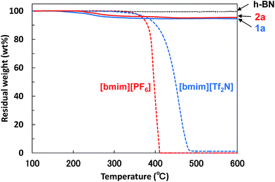 | ||
| Fig. 4 TGA diagrams of BNNS/[bmim][Tf2N] complex 1a, BNNS/[bmim][PF6] complex 2a, h-BN, [bmim][Tf2N], and [bmim][PF6]. Heating rate = 10 °C min−1, N2 atmosphere. | ||
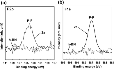
The XPS P 2p spectrum of 2a (Fig. 5a) showed a peak at approx. 134 eV, which is consistent with the peak for [PF6] anion.48 The XPS F 1s spectrum of 2a (Fig. 5b) showed a peak at approx. 687 eV, which was attributed to [PF6] anion.48–50 These XPS spectra indicate the attachment of [PF6] anions on the BNNS surfaces. In addition, the XPS surface elemental analysis for 2a (Table S2†) shows that the F/P ratio was approx. 8.5, which roughly matches the ideal F/P ratio (approx. 6) for [PF6] anions. Comparison of XPS surface elemental analysis for 2a and h-BN (Table S2†) shows that the carbon content for 2a increases compared with that for h-BN, which results from the attachment of [bmim] cations on BNNS surfaces. The XPS B 1s and N 1s spectra for 2a (Fig. S3†) showed fundamentally equal binding energies to those for h-BN, which is consistent with previously reported results for BNNSs.2 The XPS B 1s and N 1s spectra for 2a showed no clear peaks indicating covalent functionalization of B and N atoms. These results demonstrate that the BNNSs were noncovalently functionalized with [bmim][PF6]. On the other hand, as shown in Table 1, the yields of BNNS for BNNS/[bmim][PF6] complexes were higher than those for BNNS/[bmim][Tf2N] complexes. The yields for BNNS/[bmim][Tf2N] complex 1a and BNNS/[bmim][PF6] complex 2a were, respectively, 5.7 ± 1.0% and 20.7 ± 4.5% (Table 1).
3.2. Fabrication and evaluation of thermal conductivities of BNNS/IL/polymer composites
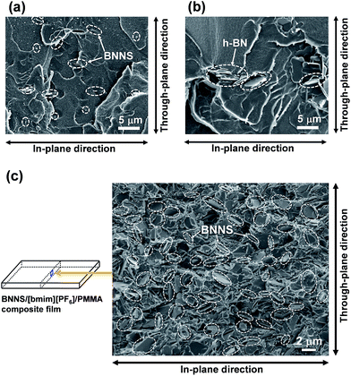
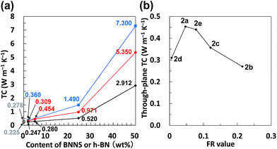
First, PMMA was used as a TP polymer because of its high solubility in common organic solvents with a low boiling point, such as acetone. BNNS/[bmim][PF6] complexes were used for preparing BNNS/IL/PMMA composites because of their higher yield than those of BNNS/[bmim][Tf2N] complexes (Table 1). BNNS/[bmim][PF6] complexes were dispersed in acetone under bath-sonication for 20 min. The resulting dispersion was mixed with PMMA/acetone solutions. After bath-sonication for 30 min, BNNS/[bmim][PF6]/PMMA/acetone solutions were obtained (Fig. 6a). BNNS/[bmim][PF6] complexes were well dispersed in PMMA/acetone solutions. The PMMA/acetone solutions have high viscosity. Therefore the use of premade BNNS/[bmim][PF6]/acetone solutions was extremely effective for preparing BNNS/[bmim][PF6]/PMMA/acetone solutions in which BNNS/[bmim][PF6] complexes were uniformly dispersed. When BNNS/[bmim][PF6] complexes were directly added to PMMA/acetone solutions, some BNNS coagulation was observed in the solution even after bath-sonication for 50 min, which is caused mainly by high-viscosity PMMA/acetone solutions. The solutions were spread on glass plates. Then BNNS/[bmim][PF6]/PMMA composite films were prepared after drying. Additionally, h-BN/PMMA composite films were also prepared. The BNNS/[bmim][PF6]/PMMA composite films showed good surface appearance (Fig. 6b and c), although the h-BN/PMMA composite films showed uneven dispersion of h-BN particles (Fig. 6d).Fig. 7 shows SEM images of frozen fracture surfaces of the films of BNNS/[bmim][PF6]/PMMA composites and h-BN/PMMA composite. Actually, the BNNSs were well dispersed in the PMMA matrix (Fig. 7a and c), although h-BN showed uneven dispersion in the matrix (Fig. 7b). This even dispersion results from physical adsorption of [bmim][PF6] on the BNNS surfaces giving good affinity with PMMA matrix because PMMA is known to have good affinity with ILs having [PF6] anions.51,52 h-BN/PMMA composite films were much more brittle than BNNS/[bmim][PF6]/PMMA composite films. The BNNS/[bmim][PF6]/PMMA composite films have good flexibility (Fig. S4†), which is because of the good compatibility of BNNS/[bmim][PF6] with PMMA. The through-plane TC of h-BN/PMMA composite containing 2 wt% of h-BN was 0.247 W m−1 K−1 (Fig. 8a), which was only 1.1 times higher than that of pristine PMMA (0.225 W m−1 K−1). However, the through-plane TC of BNNS/[bmim][PF6] (2a)/PMMA composite containing 2 wt% (≈1.1 vol%) of BNNS increased by 37% (0.309 W m−1 K−1) compared with that of PMMA. The through-plane TC of 2a/PMMA composites containing 24.5 wt% (≈14.5 vol%) of BNNS was 0.971 W m−1 K−1, which was much larger than that of h-BN/PMMA (24.5 wt%/75.5 wt%) composites (0.520 W m−1 K−1). The in-plane TC of 2a/PMMA composites was also evaluated. The in-plane TC of 2a/PMMA composites containing 2 wt% of BNNS was 0.360 W m−1 K−1, which was larger than the through-plane TC (0.309 W m−1 K−1) and in-plane TC of pristine PMMA (0.278 W m−1 K−1) (Fig. 8a). In addition, the in-plane TC of 2a/PMMA composites containing 24.5 wt% of BNNS was 1.49 W m−1 K−1, which was 1.53 times of the through-plane TC (0.971 W m−1 K−1). However, the difference between through-plane and in-plane TC was not large because BNNSs were randomly dispersed in the PMMA matrix (Fig. 7c). This random dispersion of BNNS results from noncovalent functionalization of BNNSs with [bmim][PF6] and the use of predispersed BNNS/[bmim][PF6]/acetone solutions.
When BNNS/[bmim][PF6] complex with higher FR (FR = 0.215, Table 1, 2b) was used, the through-plane TC of the obtained BNNS/[bmim][PF6]/PMMA composite containing 24.5 wt% of BNNS was extremely low (0.440 W m−1 K−1) compared with the through-plane TC (0.971 W m−1 K−1) using 2a with an FR value of 0.047. The marked increase of the amount of [bmim][PF6] on BNNS surfaces is regarded as engendering an increase of phonon scattering at the interface because the [bmim][PF6] residue on BNNS surface is amorphous. Fig. 8b shows through-plane TCs of films of BNNS/[bmim][PF6]/PMMA composites containing 5 wt% of BNNSs with different FR values. There is an optimum FR value observed at around 0.05 (Fig. 8b). Larger amounts of [bmim][PF6] on the BNNS surface led to much lower TC because [bmim][PF6] itself is amorphous, having very low TC. Meanwhile, lower amounts of [bmim][PF6] on the BNNS surfaces caused thicker BNNS layers and lower affinity between BNNS and PMMA, leading to lower TC (Fig. 8b, 2d). This result demonstrates that adjusting the FR value for BNNS/IL complex is an important factor for improving the TC of the composite. The through-plane and in-plane TCs of the BNNS/[bmim][PF6]/PMMA composites with optimum FR value (FR = 0.047) were both improved significantly (approx. 5.35 W m−1 K−1, and approx. 7.30 W m−1 K−1, respectively) with 50 wt% (≈34 vol%) BNNS loading. The through-plane and in-plane TCs were much higher than those of h-BN/PMMA (50 wt%/50 wt%) composites (approx. 2.91 W m−1 K−1, and approx. 5.45 W m−1 K−1, respectively). These results show that the use of BNNS/[bmim][PF6] complexes is extremely effective to improve the through-plane TC of the BNNS/TP polymer composites. The through-plane TC is also superior to those of previously reported BNNS/TP polymer composites with similar BNNS loadings (around 50 wt%)34,35,37 (Table S1†). Increasing the thermal conductivity of BNNS/polymer composites with relatively lower BNNS loadings (≤50 wt%) is crucially important for maintaining the mechanical properties, low density and good processability towards various applications.
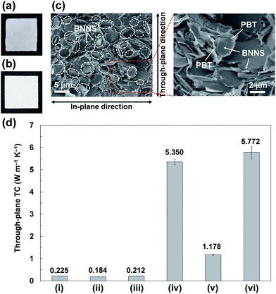
2a/PC and 2a/PBT composite films were also prepared using the same method except for using HFIP instead of acetone (Fig. 9a and b). During the process of preparing the 2a/PC composite films, 2a was not evenly dispersed in PC/HFIP solutions, giving uneven dispersion of BNNSs in 2a/PC composites (Fig. 9a). The films were also much more brittle than the films of 2a/PMMA composites because of the worse compatibility of [bmim][PF6] with PC than with PMMA. Imidazolium-based ILs reportedly show much poorer compatibility with PC than with PMMA.53 Actually, the 2a/PBT composite film was not brittle; it showed good surface appearance with uniform BNNS dispersion (Fig. 9b). The BNNSs were randomly oriented in the PBT matrix (Fig. 9c), although some apparently recoagulated during the process. The BNNS/[bmim][PF6] complexes were covered with PBT and were firmly embedded in the PBT matrix (Fig. 9c), indicating strong interactions between BNNS/[bmim][PF6] complexes and PBT. The through-plane TC of the 2a/PBT composite films containing 50 wt% of BNNS reached ∼5.77 W m−1 K−1 (Fig. 9d); the in-plane TC was ∼7.67 W m−1 K−1. Formation of the thermal-conductive paths because of the random orientation of BNNS throughout the whole composites and strong interactions between BNNS/[bmim][PF6] and PBT led to high through-plane and in-plane TCs. In addition, the through-plane TC of the BNNS/[bmim][PF6]/PBT composite films was higher than that of BNNS/[bmim][PF6]/PMMA composite films (∼5.35 W m−1 K−1), although the through-plane TC of the BNNS/[bmim][PF6]/PC composite films containing 50 wt% of BNNS was extremely low (∼1.18 W m−1 K−1) (Fig. 9d). The surface tensions of PBT, PMMA, and PC are reported respectively as ∼42.4 mJ m−2 (at 313 K), ∼40.9 mJ m−2 (at 343.2–383.2 K), and ∼33.7 mJ m−2 (at 313 K).54 The surface tension of [bmim][PF6] is ∼49 mJ m−2 (at 298 K),55 which closely matches the PBT surface tension. Therefore, the matching of their surface tensions is regarded as important for improving their affinity, leading to enhanced TC of the composites. Actually, the surface tension also played an important role to increase the solubility of BNNS/IL complex in organic solvent. BNNS/[bmim][PF6] were well dispersed in N-methyl-2-pyrrolidone (NMP), but they were insufficiently dispersed in dimethylformamide (DMF) (Fig. S5†). The surface tension value of [bmim][PF6] (∼49 mJ m−2) is closer to that of NMP (∼40 mJ m−2)56 than to that of DMF (∼36 mJ m−2).57 The BNNS/[bmim][Tf2N] complexes (surface tension of [bmim][Tf2N], ∼33 mJ m−2)55 were well dispersed in DMF, suggesting that selecting IL species is extremely important to achieve good dispersion in both organic solvents and polymers.
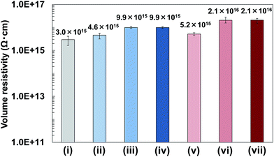
In addition, volume resistivity of 2a/PMMA composite films was evaluated. Results showed that the volume resistivity of 2a/PMMA composite films was higher than that of PMMA films (Fig. 10). Increasing BNNS content from 2 wt% to 24.5 wt% in 2a/PMMA composite films largely increased the volume resistivity (Fig. 10(v) and (vi)). The volume resistivity of 2a/PMMA composite films was also higher than that of h-BN/PMMA composite films with the same BNNS loadings (Fig. 10), which is probably due to an uneven dispersion of h-BNs in the PMMA matrix and weak interfaces between h-BNs and the matrix. In addition, volume resistivity of 2a/PBT composite films containing 50 wt% of BNNS was approx. 2.3 × 10¹⁶ Ω cm, which was also higher than PBT (approx. 3.7 × 10¹⁵ Ω cm) and h-BN/PBT (50 wt%/50 wt%) composites (approx. 1.0 × 10¹⁶ Ω cm). These results show that the use of BNNS/[bmim][PF6] complexes is very effective for improving the volume resistivity of TP polymers, although IL ([bmim][PF6]) is not an electric insulator. Actually, the FR of BNNSs with [bmim][PF6] is small, and the electrical conductivity of [bmim][PF6] itself is not high:58 much lower than traditional organic electrolytes.59 Moreover, electrically insulating BNNSs were dispersed uniformly in the matrix to increase the volume resistivity. Therefore, BNNS/[bmim][PF6]/TP polymer composites enhanced both the TC and electrical insulation.
4. Conclusions
The use of ILs afforded not only high-yield, mild, facile exfoliation of h-BNs into few-layered BNNSs but also noncovalent functionalization of BNNSs for enhanced TCs of the BNNS/TP polymer composites. h-BNs were readily exfoliated into few-layered BNNSs with micrometer-sized edges in [bmim][PF6] in high yields after simple wet-exfoliation involving sonication, giving sufficient amounts of BNNS/[bmim][PF6] complexes for the fabrication and evaluation of BNNS/[bmim][PF6]/TP polymer composites. BNNS/[bmim][PF6]/PMMA composite films were prepared using a simple wet process. In the BNNS/[bmim][PF6]/PMMA composite films, BNNS were dispersed randomly in the PMMA matrix by physical adsorption with [bmim][PF6] and a method using predispersed BNNS/[bmim][PF6]/acetone solutions. By mixing predispersed BNNS/[bmim][PF6]/acetone solutions with PMMA/acetone solutions, BNNSs were dispersed uniformly, even in the PMMA solutions with high viscosity. The through-plane and in-plane TCs for BNNS/[bmim][PF6]/PMMA composite films containing 50 wt% (≈34 vol%) of BNNS with optimum FR value (∼0.05) respectively reached ∼5.4 W m−1 K−1, and ∼7.3 W m−1 K−1. This through-plane TC is superior to that of h-BN/PMMA composites and those previously reported BNNS/TP polymer composites with similar BNNS loadings because of the randomly dispersed BNNSs and good affinity between PMMA and [PF6] anions. Optimum FR was found for enhancing the TC of the composites because a large FR value also signifies an increase of the amounts of [bmim][PF6] with amorphous structure having low TC. The optimum represents a balance of an increased effect of compatibility of BNNS surfaces with the polymer matrix and a decreased effect of TC because of increased amorphous [bmim][PF6]. The existence of an appropriate amount of [bmim][PF6] at the interface is crucially important, but the combination of IL and polymer matrix species is also important. The through-plane TC of BNNS/[bmim][PF6]/PBT composite films containing 50 wt% of BNNS with optimum FR value reached ∼5.8 W m−1 K−1, whereas that of BNNS/[bmim][PF6]/PC composite films was ∼1.2 W m−1 K−1, which resulted from lower compatibility between [bmim][PF6] and PC. Moreover, the BNNS/[bmim][PF6]/TP polymer composite films showed higher electrical insulation than pristine TP polymer and h-BN/TP polymer films. The highly thermally conductive and electrically insulating polymer nanocomposites based on BNNS/IL complexes are very promising for various applications such as next-generation power electronic devices, electric machinery, and communication equipment.Acknowledgements
We are grateful to Yoshihide Katagiri, Dr Kenzo Fukumori, and Dr Hirotaka Okamoto for helpful discussions. We thank Yoshimi Muraoka for performing some SEM measurements. We also thank Noritomo Suzuki for some TEM observations.Notes and references
- R. Gao, L. Yin, C. Wang, Y. Qi, N. Lun, L. Zhang, Y.-X. Liu, L. Kang and X. Wang, J. Phys. Chem. C, 2009, 113, 15160 CAS.
- Y. Lin and J. W. Connell, Nanoscale, 2012, 4, 6908 RSC.
- Z. Wang, Z. Tang, Q. Xue, Y. Huang, Y. Huang, M. Zhu, Z. Pei, H. Li, H. Jiang, C. Fu and C. Zhi, Chem. Rec., 2016, 16, 1204 CrossRef CAS PubMed.
- L. Lindsay and D. A. Broido, Phys. Rev. B: Condens. Matter Mater. Phys., 2011, 84, 155421 CrossRef.
- B. Mortazavi and G. Cuniberti, RSC Adv., 2014, 4, 19137 RSC.
- N. Kostoglou, K. Polychronopoulou and C. Rebholz, Vacuum, 2015, 112, 42 CrossRef CAS.
- T. Morishita, M. Matsushita, Y. Katagiri and K. Fukumori, J. Mater. Chem., 2011, 21, 5610 RSC.
- T. Morishita, Y. Katagiri, T. Matsunaga, Y. Muraoka and K. Fukumori, Compos. Sci. Technol., 2017, 142, 41 CrossRef CAS.
- A. A. Balandin, Nat. Mater., 2011, 10, 569 CrossRef CAS PubMed.
- T. Morishita, M. Matsushita, Y. Katagiri and K. Fukumori, Carbon, 2010, 48, 2308 CrossRef CAS.
- M. Shtein, R. Nadiv, M. Buzaglo, K. Kahil and O. Regev, Chem. Mater., 2015, 27, 2100 CrossRef CAS.
- Z. Spitalsky, D. Tasis, K. Papageli and C. Galiotis, Prog. Polym. Sci., 2010, 35, 357 CrossRef CAS.
- L. Song, L. Ci, H. Lu, P. B. Sorokin, C. Jin, J. Ni, A. G. Kvashnin, D. G. Kvashnin, J. Lou, B. I. Yakobson and P. M. Ajayan, Nano Lett., 2010, 10, 3209 CrossRef CAS PubMed.
- K. K. Kim, A. Hsu, X. Jia, S. M. Kim, Y. Shi, M. Hofman, D. Nezich, J. F. Rodriguez-Nieva, M. Dresselhaus, T. Palacios and J. Kong, Nano Lett., 2012, 12, 161 CrossRef PubMed.
- C. Zhi, Y. Bando, C. Tang, H. Kuwahara and D. Golberg, Adv. Mater., 2009, 21, 2889 CrossRef CAS.
- J. N. Coleman, M. Lotya, A. O'Neill, S. D. Bergin, P. J. King, U. Khan, K. Young, A. Gaucher, S. De, R. J. Smith, I. V. Shvets, S. K. Arora, G. Stanton, H. Kim, K. Lee, G. T. Kim, G. S. Duesberg, T. Hallam, J. J. Boland, J. J. Wang, J. F. Donegan, J. C. Grunlan, G. Moriarty, A. Shmeliov, R. J. Nicholls, J. M. Perkins, E. M. Grieveson, K. Theuwissen, D. W. McComb, P. D. Nellist and V. Nicolosi, Science, 2011, 331, 568 CrossRef CAS PubMed.
- H. Tao, Y. Zhang, Y. Gao, Z. Sun, C. Yan and J. Texter, Phys. Chem. Chem. Phys., 2017, 19, 921 RSC.
- W. Sun, Y. Meng, Q. Fu, F. Wang, G. Wang, W. Gao, X. Huang and F. Lu, ACS Appl. Mater. Interfaces, 2016, 8, 9881 CAS.
- T. Morishita and H. Okamoto, ACS Appl. Mater. Interfaces, 2016, 8, 27064 CAS.
- A. M. Joseph, B. Nagendra, E. Bhoje Gowd and K. P. Surendran, ACS Omega, 2016, 1, 1220 CrossRef CAS.
- Y. Hernandez, V. Nicolosi, M. Lotya, F. M. Blighe, Z. Sun, S. De, I. T. McGovern, B. Holland, M. Byrne, Y. K. Gun’ko, J. J. Boland, P. Niraj, G. Duesberg, S. Krishnamurthy, R. Goodhue, J. Hutchison, V. Scardaci, A. C. Ferrari and J. N. Coleman, Nat. Nanotechnol., 2008, 3, 563 CrossRef CAS PubMed.
- U. Khan, A. O'Neill, M. Lotya, S. De and J. N. Coleman, Small, 2010, 6, 864 CrossRef CAS PubMed.
- T. Morishita, A. J. Clancy and M. S. P. Shaffer, J. Mater. Chem. A, 2014, 2, 15022 CAS.
- H. S. Leese, L. Govada, E. Saridakis, S. Khurshid, R. Menzel, T. Morishita, A. J. Clancy, E. R. White, N. E. Chayen and M. S. P. Shaffer, Chem. Sci., 2016, 7, 2916 RSC.
- T. Morishita, H. Okamoto, Y. Katagiri, M. Matsushita and K. Fukumori, Chem. Commun., 2015, 51, 12068 RSC.
- H. M. El-Dessouky and C. A. Lawrence, Composites, Part B, 2013, 50, 91 CrossRef CAS.
- W.-L. Song, P. Wang, L. Cao, A. Anderson, M. J. Meziani, A. J. Farr and Y.-P. Sun, Angew. Chem., Int. Ed., 2012, 51, 6498 CrossRef CAS PubMed.
- M.-H. Tsai, I.-H. Tseng, J.-C. Chiang and J.-J. Li, ACS Appl. Mater. Interfaces, 2014, 6, 8639 CAS.
- K. Kim, M. Kim and J. Kim, Compos. Sci. Technol., 2014, 103, 72 CrossRef CAS.
- X.-B. Wang, Q. Weng, X. Wang, X. Li, J. Zhang, F. Liu, X.-F. Jiang, H. Guo, N. Xu, D. Golberg and Y. Bando, ACS Nano, 2014, 8, 9081 CrossRef CAS PubMed.
- J. Yu, H. Mo and P. Jiang, Polym. Adv. Technol., 2015, 26, 514 CrossRef CAS.
- Y. Xue, X. Jin, Y. Fan, R. Tian, X. Xu, J. Li, J. Zhang, L. Hu and C. Tang, Polym. Compos., 2014, 35, 1707 CrossRef CAS.
- J. Hou, G. Lia, N. Yang, L. Qin, M. E. Grami, Q. Zhang, N. Wang and X. Qu, RSC Adv., 2014, 4, 44282 RSC.
- R.-C. Zhang, D. Sun, A. Liu, S. Askari, M. Macias-Montero, P. Joseph, D. Dixon, K. Ostrikov, P. Maguire and D. Mariotti, ACS Appl. Mater. Interfaces, 2016, 8, 13567 CAS.
- S. Zhang, G. Lian, H. Si, J. Wang, X. Zhang, Q. Wang and D. Cui, J. Mater. Chem. A, 2013, 1, 5105 CAS.
- X. Huang, S. Wang, M. Zhu, K. Yang, P. Jiang, Y. Bando, D. Golberg and C. Zhi, Nanotechnology, 2015, 26, 015705 CrossRef PubMed.
- S. Li, T. Yang, H. Zou, M. Liang and Y. Chen, High Perform. Polym., 2017, 29, 315 CrossRef.
- T. Sainsbury, A. Satti, P. May, Z. Wang, I. McGovern, Y. K. Gun'ko and J. Coleman, J. Am. Chem. Soc., 2012, 134, 18758 CrossRef CAS PubMed.
- Q. Weng, X. Wang, X. Wang, Y. Bando and D. Golberg, Chem. Soc. Rev., 2016, 45, 3989 RSC.
- T. Morishita, M. Matsushita, Y. Katagiri and K. Fukumori, Carbon, 2009, 47, 2716 CrossRef CAS.
- T. Morishita, M. Matsushita, Y. Katagiri and K. Fukumori, Carbon, 2011, 49, 5185 CrossRef CAS.
- J. A. Mann and W. R. Dichtel, J. Phys. Chem. Lett., 2013, 4, 2649 CrossRef CAS.
- M. Du, Y. Wu and X. Hao, CrystEngComm, 2013, 15, 1782 RSC.
- Y. Xue, Q. Liu, G. He, K. Xu, L. Jiang, X. Hu and J. Hu, Nanoscale Res. Lett., 2013, 8, 49 CrossRef PubMed.
- J. D. Oxley, T. Prozorov and K. S. Suslick, J. Am. Chem. Soc., 2003, 125, 11138 CrossRef CAS PubMed.
- E. B. Flint and K. S. Suslick, Science, 1991, 253, 1397 CrossRef CAS PubMed.
- M. Shakourian-Fard, G. Kamath and Z. Jamshidi, J. Phys. Chem. C, 2014, 118, 26003 CAS.
- D. Ensling, M. Stjerndahl, A. Nytén, T. Gustafsson and J. O. A. Thomas, J. Mater. Chem., 2009, 19, 82 RSC.
- X. Liu, J. Pu, L. Wang and Q. Xue, J. Mater. Chem. A, 2013, 1, 3797 CAS.
- Y. M. Shul'ga, A. V. Bulatov, R. A. T. Gould, W. V. Konze and L. H. Pignolet, Inorg. Chem., 1992, 31, 4704 CrossRef.
- K. Ueno, T. Fukai, T. Nagatsuka, T. Yasuda and M. Watanabe, Langmuir, 2014, 30, 3228 CrossRef CAS PubMed.
- L. Zhao, Y. Li, X. Cao, J. You and W. Dong, Nanotechnology, 2012, 23, 255702 CrossRef PubMed.
- F. J. Carrión, C. Espejo, J. Sanes and M. D. Bermúdez, Compos. Sci. Technol., 2010, 70, 2160 CrossRef.
- J. M. R. C. A. Santos, K. Fagelman and J. T. Guthrie, J. Chromatogr. A, 2002, 969, 119 CrossRef CAS PubMed.
- M. Tariq, M. G. Freire, B. Saramago, J. A. P. Coutinho, J. N. C. Lopes and L. P. N. Rebelo, Chem. Soc. Rev., 2012, 41, 829 RSC.
- S. D. Bergin, V. Nicolosi, P. V. Streich, S. Giordani, Z. Sun, A. H. Windle, P. Ryan, N. P. P. Niraj, Z.-T. T. Wang, L. Carpenter, W. J. Blau, J. J. Boland, J. P. Hamilton and J. N. Coleman, Adv. Mater., 2008, 20, 1876 CrossRef CAS.
- H. Kahl, T. Wadewitz and J. Winkelmann, J. Chem. Eng. Data, 2003, 48, 580 CrossRef CAS.
- O. Zech, A. Stoppa, R. Buchner and W. Kunz, J. Chem. Eng. Data, 2010, 55, 1774 CrossRef CAS.
- Q.-G. Zhang, S.-S. Sun, S. Pitula, Q.-S. Liu, U. Welz-Biermann and J.-J. Zhang, J. Chem. Eng. Data, 2011, 56, 4659 CrossRef CAS.
Footnote |
| † Electronic supplementary information (ESI) available: ESI tables and figures. See DOI: 10.1039/c7ra06691k |
| This journal is © The Royal Society of Chemistry 2017 |

