 Open Access Article
Creative Commons Attribution 3.0 Unported Licence
Theoretical prediction of the mechanical properties of zeolitic imidazolate frameworks (ZIFs)†
Bin Zheng *a,
Yihan Zhub,
Fang Fua,
Lian Li Wanga,
Jinlei Wanga and
Huiling Dua
aSchool of Materials Science and Engineering, Xi'an University of Science and Technology, Xi'an 710054, PR China. E-mail: zhengbin@xust.edu.cn
bDivision of Physical Sciences and Engineering, King Abdullah University of Science and Technology (KAUST), Thuwal 23955-6900, Saudi Arabia
First published on 25th August 2017
Abstract
A good resistance against mechanical stress is essential for the utilization of metal–organic frameworks (MOFs) in practical applications such as gas sorption, separation, catalysis or energy conversion. Here, we report on the successful modification of the mechanical properties of zeolitic imidazolate frameworks (ZIFs) achieved through a substitution of the terminal group. The mechanical modulus of SALEM-2 was found to significantly improve when the –H groups at position 2 of the imidazole linkers were replaced with electron withdrawing groups (–CHO, –Cl, or –Br). The charge distribution and electron density were analyzed to reveal the mechanism behind the observed variation of the elastic stiffness. Furthermore, ZIF-I with a –I group at position 2 of the imidazole linkers was predicted to exhibit an excellent mechanical strength in our study and then prepared experimentally. The results indicate that an inconspicuous change of the structure of ZIFs, i.e., additional groups strengthening the ZnN4 tetrahedron, will lead to a stiffer framework.
Introduction
Metal–organic frameworks (MOFs) are porous crystalline materials containing organic and inorganic moieties which form a regular three-dimensional lattice.1 Their highly tunable structure allows to engineer bespoke materials with the desired properties to fit the target application, e.g., in the fields of gas storage, separation, catalysis or sensing, as well as for energy conversion.2–7 However, the mechanical instability of some MOFs limits their commercial and industrial application potential. For instance, a loss of porosity may occur during the shaping or post-synthetic processing of MOF powders through mechanical pelletization, extrusion or sintering (i.e., the formation of a solid mass through heating).8,9Due to their exceptionally high chemical and thermal stability, zeolitic imidazolate frameworks (ZIFs) are among the most frequently investigated MOFs.10 The earliest study on the mechanical stability of ZIFs was conducted by Tan et al., who performed single-crystal nanoindentation tests.11 They found the mechanical properties of ZIFs to be superior to the corresponding properties of other MOFs and to be mainly determined through the rigidity and bulkiness of the substituted imidazolate linkers. Further experimental and theoretical investigations revealed that ZIF-8 exhibits an exceptionally low shear modulus below 1 GPa,12–15 which is much lower than values previously reported for single-crystalline extended solids. In particular, the shear elastic constant (C44) of the cubic ZIF-8 was found to decrease with the applied external pressure, an effect which is called shear mode softening.16 The weak resistance against shear deformation was later verified by the observation that ZIF-8 might undergo a rapid and catastrophic porosity collapse during ball-milling.17,18
The addition of modulator ligands is a common approach to improve the mechanical robustness of MOFs.11,17,19 However, this may induce a structural instability through guest–host interaction,20 and/or reduce the framework's porosity. Overcoming the limitations imposed by this trade-off relationship between the elastic stiffness and the framework's porosity therefore remains the main challenge when aiming to improve the mechanical properties of MOFs.
Enormous efforts have been made to experimentally determine the elastic and bulk modulus of ZIFs.11,12,21–23 However, the low number of reports suggests that it is much more difficult to experimentally determine the corresponding shear modulus.12 Therefore, the theoretical computation of the mechanical modulus of ZIFs has become an important alternative,12,15,16 although it remains challenging to obtain accurate values through computational methods.24 Yet a comparison of the mechanical modulus values obtained for different ZIFs might yield important insights.
In this work, we employed density functional theory (DFT) calculations to investigate the mechanical properties of four ZIFs of the same geometry in order to isolate the effect of linker functionalization on the strength of MOFs. In particular, we demonstrate that small changes in the linker molecules can have a drastic impact on the mechanical properties of the studied ZIFs. These results are expected to be helpful for designing future ZIF materials with excellent mechanical properties.
Theoretical methods
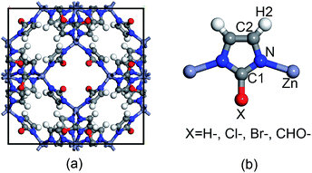
The topological unit of the ZIF structures studied in this work consists of two Zn tetrahedrons linked via an imidazole ring. Substituting the terminal group of imidazole has been demonstrated to be a good strategy to tune the properties of ZIFs without having to change its symmetry. Our calculations were performed for four types of ZIFs (Fig. 1), which have been experimentally investigated before and share the same sodalite (SOD) topology but contain different functional groups: SALEM-2,25 in which the linker is an unfunctionalized imidazolate; ZIF-Cl,26 with a chloro-functionalized linker (cim = 2-chloroimidazolate); ZIF-Br,26 with a bromo-functionalized linker (bim = 2-bromoimidazole); and ZIF-90,27 where the linker (ica = imidazolate-2-carboxaldehyde) contains a aldehyde group. Other terminal functional groups, such as stronger electron donating groups (–NH2) or stronger electron withdrawing groups (–NO2), were not included in this study because we decided to focus on real ZIF structures and exclude purely hypothetical frameworks. Although 2-nitroimidazole can be used to synthesize an SOD framework, the metal center is Co instead of Zn.28 | ||
| Fig. 1 Representation of (a) the unit cell of ZIFs with an SOD topology and (b) the basic unit of ZIFs with the different functional groups studied in this work. | ||
In this study, the calculations were performed utilizing the CASTEP code29 based on density functional theory (DFT).30,31 Different exchange–correlation functions with or without dispersion interaction corrections were tested (Tables S1 and S2†). We found that utilizing a generalized gradient approximation functional with Perdew–Burke–Ernzerhof parametrization (GGA-PBE)32 using Vanderbilt's ultrasoft pseudopotential33 and including dispersion corrections improved the reproduction of the experimental lattice parameters for most of the ZIFs studied in this work. The geometry optimization was performed employing the Broyden–Fletcher–Goldfarb–Shanno (BFGS) algorithm,34 with the cutoff energy selected to be 500 eV. 3 × 3 × 3 Monkhorst–Pack k-point meshes35 were chosen for the Brillouin zone sampling to achieve a total energy convergence lower than 1 × 10⁻⁵ eV per atom, a maximum Hellmann–Feynman force of 0.03 eV Å−1, a maximum ionic displacement of 0.001 Å and a maximum stress of 0.05 GPa. The fineness of the cutoff energy and the k-mesh used in our DFT calculations were tested and the results are presented in Fig. S1 and S2.† The finite basis set correction method was employed to optimize the unit cell parameters.
The elastic constants cij were calculated through cij = σi/εj, where σ and ε are the elastic stress and strain, respectively, and the subscripts i and j denote the Cartesian coordinates of the considered structures.36 A 1% strain was chosen to guarantee a purely elastic response. For the optimization of the internal atomic freedoms, the criteria for convergence were selected in such a way that the difference in total energy was lower than 2 × 10⁻⁶ eV per atom, the maximum force was 0.006 eV Å−1 and the maximum displacement was 2 × 10⁻⁴ Å. Although the computed mechanical modulus of the ZIFs depends on the selected exchange–correlation functions and the dispersion correction, the variation trend of the mechanical properties obtained for the different ZIFs proved to be consistent (Table S2†).
Results and discussion
In this work, the mechanical properties were obtained through a tensorial analysis of the single-crystal elastic constants, Cij. For the cubic phase, three non-zero independent elastic constants, i.e., C11, C12, and C44 (Table 1), were used to compute the mechanical properties. The coefficient C11 (=C22 = C33) indicates the stiffness along the crystal axis a (b or c), the coefficient C12 (=C21) corresponds to the tensile–tensile coupling between the crystal axes a and b, and the shear coefficient C44 (=C55 = C66) corresponds to the stiffness against angular distortion when the cell is subjected to shear strain. The elastic constants determined for the studied ZIFs, which are listed in Table 1, satisfy the fundamental elastic stability criteria, which imposes the following restrictions on a cubic crystal: C11 > ∣C12∣, C11 + 2 C12 > 0, and C44 > 0.37 The elastic stability criterion was based on the convexity requirement of the equilibrium free energy of a stress-free crystal under small strain fluctuation, according to the theory of lattice dynamics.38 In order to satisfy above demand, the single-crystal elastic constant matrix must be positive definite and then the restrictions on any types of crystal can be obtained.| SALEM-2 | ZIF-90 | ZIF-Cl | ZIF-Br | |
|---|---|---|---|---|
| C11 | 8.949 | 8.513 | 12.302 | 15.921 |
| C12 | 7.584 | 8.111 | 9.977 | 11.566 |
| C44 | 2.358 | 2.502 | 3.578 | 6.562 |
| S11 | 0.502 | 0.489 | 0.297 | 0.162 |
| S12 | −0.230 | −0.225 | −0.133 | −0.068 |
| S44 | 0.424 | 0.400 | 0.279 | 0.152 |
| G | 1.44 | 1.51 | 2.28 | 4.22 |
| E | 1.99 | 2.05 | 3.37 | 6.19 |
| B | 8.04 | 8.58 | 10.75 | 13.02 |
According to the results presented in Table 1, the elastic constants C11, C12 and C44 do not depend on the size of the terminal group. ZIF-90 exhibits a large group size (–CHO) but low C11 and C44 values. This indicates that it is the electronegativity of the terminal group which mainly contributes to the deformation resistance of the ZIFs and not the geometry. Here, we therefore only focus on the contribution of the electronegativity of the terminal groups and neglect the effect of the geometrical shape.
The shear modulus G may serve as a measure of the rigidity of the framework against structural distortion due to external shear forces. In this work, the G values were computed using eqn (1).39 Young's modulus E is defined as the reciprocal of the elastic compliance constants (eqn (2)). The bulk modulus B represents the resistance of the structure against volumetric strain under hydrostatic pressure and can be computed through eqn (3).
| GV = (C11 − C12 + 3C44)/5 |
| GR = 5/[4(S11 − S12) + 3S44] S = C−1 |
| GH = (GV + GR)/2 | (1) |
| E = 1/S11 (S11 = S22 = S33) | (2) |
| B = (C11 + 2C12)/3 | (3) |
| Type | Atomic charge | |||||
|---|---|---|---|---|---|---|
| Zn | N | C1 | C2 | H2 | X | |
| SALEM-2 | 1.52 | −0.52 | −0.03 | −0.20 | 0.24 | 0.24 |
| ZIF-90 | 1.51 | −0.51 | 0.19 | −0.18 | 0.26 | −0.06 |
| ZIF-Cl | 1.42 | −0.51 | 0.19 | −0.19 | 0.25 | 0.01 |
| ZIF-Br | 1.35 | −0.49 | 0.13 | −0.20 | 0.24 | 0.10 |
| ZIF-I | 1.34 | −0.49 | 0.05 | −0.20 | 0.23 | 0.18 |
According to eqn (1), the shear modulus strongly depends on the shear coefficient C44. The larger the C44 value, the higher the shear modulus (G). Table 1 shows that ZIF-Br exhibits the largest shear modulus, followed by ZIF-Cl, ZIF-90 and SALEM-2.
Similarly, the highest Young's modulus (E) was also obtained for ZIF-Br due to its higher C11 value. Table 1 also reveals the same order, i.e., ZIF-Br, ZIF-Cl, ZIF-90 and SALEM-2 (from high to low), for the bulk modulus (B). Excellent overall mechanical properties (G, E and B) were obtained for ZIF-Br, followed by ZIF-Cl, ZIF-90 and SALEM-2 (Table 1).
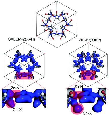
In order to better understand the variation of the mechanical properties of ZIFs, we have analyzed their charge distribution. The calculated Mulliken atomic charges (q) of the four ZIFs investigated in this study are summarized in Table 2. The results show that the charge distribution throughout all of the ZIFs hardly changes, except for the Zn and C1 atoms and the terminal groups. The ZIFs can be divided into two groups according to the electronegativity of the terminal groups. The first group only consists of SALEM-2, which features the electron donating group –H (q = 0.240). A conical shape of the electron density distribution was obtained for the C–H bond (the left circular shade in Fig. 2) in SALEM-2, indicating an electron transfer from the –H group to the 5-member ring. The other three ZIFs studied here form the second group as they contain an electron withdrawing group (EWG). The electron density distribution in the terminal group features a dumbbell shape. The –Cl group show the highest electron-withdrawing ability, followed by –Br and –CHO. The analysis of the results presented in Tables 1 and 2 revealed two interesting phenomena: first, the mechanical strength can benefit from the presence of an EWG located at position 2 of the imidazole ring. The weakest mechanical strength was obtained for SALEM-2 due to its electron donating group (EDG). Second, the mechanical strength of a ZIF becomes weaker if a strong EWG is present, such as the –CHO group in ZIF-90.
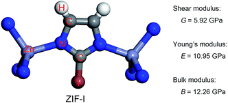
The charge transfer model can be used to explain the above phenomena. Table 2 shows that the Zn atoms are positively charged with q ranging from 1.52 for SALEM-2 to 1.35 for ZIF-Br, which indicates a reduction of the electron donation by the Zn atoms. While the charge of the N atoms remains almost constant, the electrons donated by the Zn atoms will eventually contribute to the charge of the C1 atoms (Table 2). The electron loss at the Zn–N bond lowers the local electron density (Fig. 2), thereby reducing the strength of the ZnN4 tetrahedral, which ultimately determines the mechanical properties of the ZIFs.40 In this regard, terminal groups with a weak electron-withdrawing ability can contribute to the electron accumulation in ZnN4, thus strengthening the ZIFs. The above relation between the electron-withdrawing ability of the terminal group and the framework strength could be further validated through investigating the mechanical properties of ZIF-I (Fig. 3), where the linker (iim = 2-iodoimidazole) features a –I group with a comparatively weak electron-withdrawing ability (Table 2). As expected, ZIF-I exhibits a larger mechanical modulus (Fig. 3) than the other ZIFs (Table 1). We then successfully synthesized ZIF-I (ESI†) to prove that it is not just a hypothetical structure.
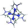
In previous studies,40 we have argued that the axial stretching and shear deformation of ZIFs depend on the Zn–N bond length and the N–Zn–N angle, respectively. Here, we used the cluster model to quantify the enhancing effect of the terminal group on the bond length and angle in ZnN4 (Table 3). The model and computational details can be found in the ESI.† The results presented in Table 3 clearly show that the force constants (Kb and Ka) obtained for the Zn–N bond and the N–Zn–N angle stretching increase as the electron-withdrawing ability of the terminal groups decreases. The results calculated using the cluster model are consistent with the information given in the periodic table, again confirming that the strength of the ZnN4 tetrahedral and thereby the mechanical properties of ZIFs can be adjusted by replacing the EWGs.
Conclusions
In summary, we have computed and assessed the complete elastic properties of the experimentally accessible ZIFs with SOD geometry by means of ab initio density functional theory (DFT). Our calculation results indicate that ZIF-Br with its weak electron withdrawing group (EWG) may exhibit excellent overall mechanical properties (G, E and B). In comparison, strong EWGs, such as –Cl in ZIF-Cl and –CHO in ZIF-90, can attract more electrons from the Zn atoms. These electrons then aggregate at the C atoms directly bonded to the EWGs. The resulting lower electron density in the ZnN4 tetrahedrons weakens the bond and angle strength and thereby the mechanical strength of the ZIFs. Considering these results, a new synthesized ZIF structure (ZIF-I) with a terminal group that exhibits a low electron-withdrawing ability was modeled and predicted to possess even better mechanical properties than ZIF-Br. In this work the cluster model was used to compute the force parameters of the Zn–N bond and the N–Zn–N angle stretching, confirming the enhancing effect of the terminal groups. The substitution of the terminal groups therefore seems a promising strategy to obtain strong MOFs which retain their high porosity and are capable of resisting the pressure or stresses involved in practical applications.Conflicts of interest
There are no conflicts to declare.Acknowledgements
This work was supported by the Natural Science Foundation of China under grant 21503165 and 51372197, Shaanxi Province 100 plan, and the Key Innovation Team of Shaanxi Province (2014KCT-04).References
- H. Furukawa, K. E. Cordova, M. O'Keeffe and O. M. Yaghi, Science, 2013, 341, 974 CrossRef CAS PubMed.
- J.-R. Li, R. J. Kuppler and H.-C. Zhou, Chem. Soc. Rev., 2009, 38, 1477 RSC.
- T. R. Zeitler, T. Van Heest, D. S. Sholl, M. D. Allendorf and J. A. Greathouse, ChemPhysChem, 2013, 14, 3740 CrossRef CAS PubMed.
- S. Bai, X. Liu, K. Zhu, S. Wu and H. Zhou, Nat. Energy, 2016, 1, 16094 CrossRef CAS.
- F.-K. Shieh, S.-C. Wang, C.-I. Yen, C.-C. Wu, S. Dutta, L.-Y. Chou, J. V. Morabito, P. Hu, M.-H. Hsu, K. C. W. Wu and C.-K. Tsung, J. Am. Chem. Soc., 2015, 137, 4276 CrossRef CAS PubMed.
- Y.-C. Sue, J.-W. Wu, S.-E. Chung, C.-H. Kang, K.-L. Tung, K. C. W. Wu and F.-K. Shieh, ACS Appl. Mater. Interfaces, 2014, 6, 5192 CAS.
- F.-K. Shieh, S.-C. Wang, S.-Y. Leo and K. C. W. Wu, Chem.–Eur. J., 2013, 19, 11139 CrossRef CAS PubMed.
- D. Bazer-Bachi, L. Assié, V. Lecocq, B. Harbuzaru and V. Falk, Powder Technol., 2014, 255, 52 CrossRef CAS.
- J. C. Tan and A. K. Cheetham, Chem. Soc. Rev., 2011, 40, 1059 RSC.
- K. S. Park, Z. Ni, A. P. Côté, J. Y. Choi, R. Huang, F. J. Uribe-Romo, H. K. Chae, M. O'Keeffe and O. M. Yaghi, Proc. Natl. Acad. Sci. U. S. A., 2006, 103, 10186 CrossRef CAS PubMed.
- J. C. Tan, T. D. Bennett and A. K. Cheetham, Proc. Natl. Acad. Sci. U. S. A., 2010, 107, 9938 CrossRef CAS PubMed.
- J. C. Tan, B. Civalleri, C.-C. Lin, L. Valenzano, R. Galvelis, P.-F. Chen, T. D. Bennett, C. Mellot-Draznieks, C. M. Zicovich-Wilson and A. K. Cheetham, Phys. Rev. Lett., 2012, 108, 095502 CrossRef PubMed.
- M. R. Ryder and J.-C. Tan, Dalton Trans., 2016, 45, 4154 RSC.
- L. Bouëssel du Bourg, A. U. Ortiz, A. Boutin and F.-X. Coudert, APL Mater., 2014, 2, 124110 CrossRef.
- J. C. Tan, B. Civalleri, A. Erba and E. Albanese, CrystEngComm, 2015, 17, 375 RSC.
- A. U. Ortiz, A. Boutin, A. H. Fuchs and F.-X. Coudert, J. Phys. Chem. Lett., 2013, 4, 1861 CrossRef CAS PubMed.
- B. Van de Voorde, I. Stassen, B. Bueken, F. Vermoortele, D. De Vos, R. Ameloot, J.-C. Tan and T. D. Bennett, J. Mater. Chem. A, 2015, 3, 1737 CAS.
- T. D. Bennett, P. J. Saines, D. A. Keen, J.-C. Tan and A. K. Cheetham, Chem.–Eur. J., 2013, 19, 7049 CrossRef CAS PubMed.
- J. Im, N. Yim, J. Kim, T. Vogt and Y. Lee, J. Am. Chem. Soc., 2016, 138, 11477 CrossRef CAS PubMed.
- P. Zhao, G. I. Lampronti, G. O. Lloyd, M. T. Wharmby, S. Facq, A. K. Cheetham and S. A. T. Redfern, Chem. Mater., 2014, 26, 1767 CrossRef CAS PubMed.
- Z. Su, Y.-R. Miao, S.-M. Mao, G.-H. Zhang, S. Dillon, J. T. Miller and K. S. Suslick, J. Am. Chem. Soc., 2015, 137, 1750 CrossRef CAS PubMed.
- T. D. Bennett, Y. Yue, P. Li, A. Qiao, H. Tao, N. G. Greaves, T. Richards, G. I. Lampronti, S. A. T. Redfern, F. Blanc, O. K. Farha, J. T. Hupp, A. K. Cheetham and D. A. Keen, J. Am. Chem. Soc., 2016, 138, 3484 CrossRef CAS PubMed.
- T. D. Bennett, J. C. Tan, Y. Z. Yue, E. Baxter, C. Ducati, N. J. Terrill, H. H. M. Yeung, Z. F. Zhou, W. L. Chen, S. Henke, A. K. Cheetham and G. N. Greaves, Nat. Commun., 2015, 6, 8079 CrossRef CAS PubMed.
- M. R. Ryder, B. Civalleri and J.-C. Tan, Phys. Chem. Chem. Phys., 2016, 18, 9079 RSC.
- O. Karagiaridi, M. B. Lalonde, W. Bury, A. A. Sarjeant, O. K. Farha and J. T. Hupp, J. Am. Chem. Soc., 2012, 134, 18790 CrossRef CAS PubMed.
- K. Li, D. H. Olson, J. Seidel, T. J. Emge, H. Gong, H. Zeng and J. Li, J. Am. Chem. Soc., 2009, 131, 10368 CrossRef CAS PubMed.
- W. Morris, C. J. Doonan, H. Furukawa, R. Banerjee and O. M. Yaghi, J. Am. Chem. Soc., 2008, 130, 12626 CrossRef CAS PubMed.
- B. P. Biswal, T. Panda and R. Banerjee, Chem. Commun., 2012, 48, 11868 RSC.
- S. J. Clark, M. D. Segall and C. J. Pickard, Z. Kristallogr., 2005, 220, 567 CAS.
- P. Hohenberg and W. Kohn, Phys. Rev., 1964, 136, B864 CrossRef.
- W. Kohn and L. J. Sham, Phys. Rev., 1965, 140, A1133 CrossRef.
- J. P. Perdew, K. Burke and M. Ernzerhof, Phys. Rev. Lett., 1996, 77, 3865 CrossRef CAS PubMed.
- D. Vanderbilt, Phys. Rev. B: Condens. Matter Mater. Phys., 1990, 41, 7892 CrossRef.
- B. G. Pfrommer, M. Côté, S. G. Louie and M. L. Cohen, J. Comput. Phys., 1997, 131, 233 CrossRef CAS.
- H. J. Monkhorst and J. D. Pack, Phys. Rev. B: Solid State, 1976, 13, 5188 CrossRef.
- O. H. Nielsen and R. M. Martin, Phys. Rev. Lett., 1983, 50, 697 CrossRef CAS.
- J. F. Nye, Physical Properties of Crystals, Clarendon, Oxford, 1985 Search PubMed.
- W. Hao and L. Mo, J. Phys.: Condens. Matter, 2012, 24, 245402 CrossRef PubMed.
- R. Hill, Proc. Phys. Soc., London, Sect. A, 1952, 65, 349 CrossRef.
- B. Zheng, L. L. Wang, J. C. Hui, L. Du, H. Du and M. Zhu, Dalton Trans., 2016, 45, 4346 RSC.
Footnote |
| † Electronic supplementary information (ESI) available: Calculation details and results using different models. See DOI: 10.1039/c7ra07242b |
| This journal is © The Royal Society of Chemistry 2017 |


