 Open Access Article
A sustainable hierarchical carbon derived from cultivated fibroid fungus for high performance lithium–sulfur batteries†
Huali Wua,
Jiafu Linb,
Jirong Moua,
Qiaoji Zhenga and
Dunmin Lin *a
*a
aCollege of Chemistry and Materials Science, Sichuan Normal University, Chengdu 610066, China. E-mail: ddmd222@sicnu.edu.cn; Fax: +86 28 84760802; Tel: +86 28 84760802
bAntibiotics Research and Re-evaluation Key Laboratory of Sichuan Province, Sichuan Industrial Institute of Antibiotics, Chengdu University, Chengdu, 400001, China
First published on 10th October 2017
Abstract
Biomass plays an important role in constructing carbon materials, but is always restricted by the non-tunable and non-standard characteristics of its precursors. In this study, we employed a new sustainable microorganism-route to synthesize the fibroid fungus that could be used as the precursor to prepare sulfur host materials for lithium sulfur batteries. The H3PO4-activated fibroid fungus presents a controllable nano- and micro-structure after high temperature carbonization, which can effectively suppress polysulfides dissolution and supply space for sulfur accommodation due to its high specific surface area of 509 m2 g−1 and pore volume of 0.69 m3 g−1. As a result, the assembled lithium sulfur (Li–S) battery shows a high initial specific discharge capacity of 1319 mA h g−1 at 0.1C and maintains a capacity of 663 mA h g−1 after 100 cycles, corresponding to the outstanding reaction kinetics and cycling stability. Our results display an eco-friendly, renewable and controlled synthesis process of porous carbon, which features a promising application in preparing versatile electrodes in energy storage.
1. Introduction
With the ever-growing development of electrical vehicles and the electronic manufacturing industry, energy storage devices with high capacity, superior energy density, long lifespan and eco-friendliness are a proposed response to the present energy crisis.1 Therefore, a high-energy storage system is urgently needed to study and apply in our daily life. The lithium sulfur battery has been regarded as one of the most promising candidates due to its high theoretical discharge capacity of 1675 mA h g−1 and high energy density of 2600 W h kg−1.2–4 Apart from its towering advantages, the practical application of Li–S batteries still suffers from several drawbacks such as the insulating essence of sulfur (5 × 10⁻³⁰ S cm−1 at 25 °C), shuttle effect and volumetric expansion (almost 78%) during lithiation.2,4Extensive efforts have been made to respond to the aforementioned problems, including fabricating various sulfur composites by dispersing sulfur into conducting materials to enhance the conductivity,5–8 optimizing the liquid electrolyte or employing solid electrolytes,9,10 protecting the anode via coating and electrolyte additives11,12 and using new binders to stabilize the electrode structure or cell configuration.13,14 Among these, constructing the composites with sulfur particles embedded within conductive meso/microporous carbon frameworks has proven to be promising, because the porous carbon material not only improves sulfur utilization by keeping sulfur particles nanometer-sized and electrically connected, but can also adsorb sulfur and/or polysulfides on their large internal surfaces, rendering redeposition more uniform and mitigating polysulfides diffusion. The pioneering work reported by Nazar5 and co-workers employing the mesoporous carbon to encapsulate the polysulphides as well as active material sulfur within the conductivity material has demonstrated that porous carbon can be effective in mitigating the above-mentioned issues, and on the other hand, guide improvement in the electrochemical performance of lithium sulfur batteries. Since then, various carbon materials have been widely investigated and designed for trapping polysulfides, such as porous carbon,2 carbon nanotubes,15 graphene,16 and graphene oxides.17 Although significant improvements in terms of rate capability and stability have been achieved by employing these carbon matrices, the synthesis process of these carbon materials is generally complicated and therefore expensive and lacks scalability and consistency. Thus, it is necessary to find highly efficient and inexpensive sources of porous carbon to build high performance sulfur-based composites.
Biomass carbon, as a readily available, eco-friendly and sustainable carbon resource, has attracted increasing attention and has been frequently focused on constructing carbon/sulfur composites over the past few years. Nevertheless, most biomass carbon materials are always used after the organism is completely formed, which restricts the base properties of the material itself. Furthermore, the consistency and universality of the prevalent biochars are difficult to guarantee during their forming process due to various uncertain factors.18 More recently, designing and fabricating monolithic carbon materials based on the combination of various subjects have attracted extensive attention. For example, Chai's group19 has synthesized porous monolithic carbon from microorganisms to act as the interlayer in lithium sulfur batteries and obtained improved electrochemical properties. However, the introduction of the interlayer always leads to a relatively big impedance for Li+ and/or e− transport in the charge/discharge process, which is very important in evaluating the comprehensive electrochemical performance of lithium sulfur batteries. Therefore, compared to the interlayer, constructing porous carbon derived from microorganisms to serve as the sulfur host can be a simpler and more available strategy to enhance the electrochemical performance of lithium sulfur batteries.
In this study, a sustainable biochars synthetic method was proposed based on simple H3PO4 activation and subsequent pyrolysis of fibrous fungus (Aspergillus capestris), which were cultured by a new sustainable microorganism-route. The original synthetic route results in a conductive and hierarchical carbon matrix, which contributes to an enhanced electrochemical performance because of the fibrous fungus nature. In comparison to previously reported nanocarbons,15–17 the fungi-based biomass material is more eco-friendly, uniform and economical and can be easily decorated during the synthetic process. In this consideration, it can raise great interest in developing various carbon electrodes for energy storage devices, such as lithium batteries, catalysis and hydrogen storage.
2. Experimental
2.1 Materials synthesis
2.2 Electrochemical measurements
The cathode material was obtained by dissolving 80 wt% carbon/sulfur composites, 10 wt% super-p and 10 wt% PVDF in N-methyl-2-pyrrolidinone (NMP) under magnetic stirring. Then, the mixture was coated onto an aluminium foil, dried at 60 °C for 12 h, and cut into wafers with sulfur content of 1.5–1.6 mg cm−2. The electrochemical experiments were conducted on coin cells (CR2032) with the organic electrolyte LiN(CF3SO2)2 (LiTFSI) and a membrane of Celgard 2400, and assembled in an Ar filled glove box (MB-Labstar, Germany). Cyclic voltammetry (CV) and electrochemical impedance spectroscopy (EIS) measurements were obtained on an electrochemical station (CHI660E, Shanghai, China). The cyclic voltammetry curves were conducted with a scanning rate of 0.1 mV s−1 between 1.5 and 3.0 V. The impedance spectra were obtained in the frequency range from 100 kHz to 10 mHz and fitted using ZView software. Galvanostatic charge/discharge tests were carried out on a battery test system (LAND, CT2100A, China) between 1.7 and 3.0 V. All electrochemical measurements were performed at room temperature.3. Results and discussion
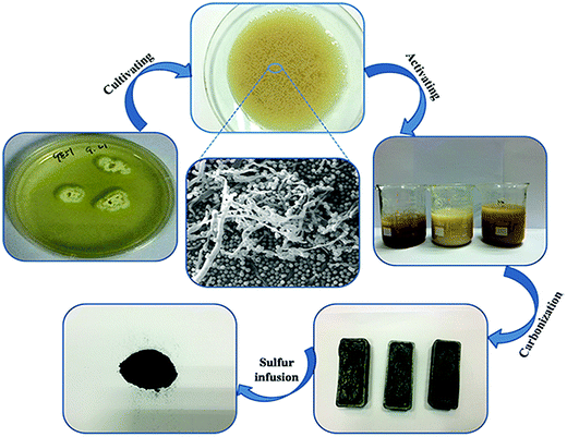
As shown in Fig. 1, the HAFC/S composite was synthesized by a series of steps. First, potato infusion derived fungus was cultured in a solid medium. The fungus spores on the solid medium were adopted as the microorganism source and transferred to a fluid medium. The micromorphology of the fungal spores was analyzed by scanning electron microscopy (SEM), as shown in Fig. 1, which presents a globular and fibrous interconnected structure. The fibrous branches were developed by the fungal spores under the cultivating process. When the concentration of cultivated fungus was close to maximum (about 11 mg mL−1), the abundant fibrous fungus was immediately collected to act as the precursor. Immediately, the H3PO4 activated fibrous fungus was carbonized at high temperature in a N2 atmosphere to obtain a hierarchical porous carbon. Finally, the sulfur was immersed into the porous carbon to construct the carbon/sulfur composites by the classic melt diffusion approach. A 5![[thin space (1/6-em)]](https://www.rsc.org/images/entities/char_2009.gif) :
:![[thin space (1/6-em)]](https://www.rsc.org/images/entities/char_2009.gif) 5 weight ratio mixture of HAFC/nAFC and sulfur was heated just above the melting point of sulfur, where the viscosity is lowest. The melt sulfur is imbibed into the channels by capillary forces, whereupon it solidifies and shrinks to form sulfur nanofibers that are in intimate contact with the conductive carbon walls.
5 weight ratio mixture of HAFC/nAFC and sulfur was heated just above the melting point of sulfur, where the viscosity is lowest. The melt sulfur is imbibed into the channels by capillary forces, whereupon it solidifies and shrinks to form sulfur nanofibers that are in intimate contact with the conductive carbon walls.
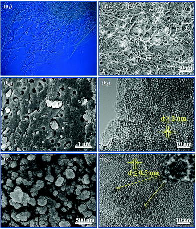
The optical microscopic graph of the fungus is shown in Fig. 2a1, in which many fibroid fungi and spherical conidia are interlocked with each other. The abundant fibroid fungus was synthesized by cultivating the spherical conidia in stationary phases. Fig. 2a2 displays the morphology of the fibroid fungus in 500-times magnification, which shows an interlocked framework because of the disordered growth direction of the fibroid fungus in stationary phases, indicating that the fibroid fungus may be an excellent supporter for sulfur storing or polysulfides encapsulation. Therefore, the fibroid fungus were collected and carbonized to act as the carbon matrix to store sulfur and encapsulate the various polysulfides. As shown in Fig. 2b1, a great number of macropores and mesopores were found in the pure fungus after high temperature carbonization, which may be caused by abundant gas production and release (CO, CO2 and H2O). Furthermore, the TEM image (Fig. 2b2) of nAFC also displays large-scale white dots, implying that most of the nanopores in nAFC are macropores (50–100 nm). For the nAFC material, sulfur cannot be completely encapsulated into the porous structure due to the limited surface area and pore volume of the material, which is identified in Fig. 3c and d. Hence, some particles are aggregated together on the surface of nAFC/S (Fig. S1a1†). The TEM image (Fig. S1a2†) of nAFC/S presents a shadow area, which also suggests that excess sulfur cannot be incorporated into the relatively dense carbon material. In particular, the H3PO4-activated and carbonized fungus (HAFC) shows a cauliflower-like fluffy morphology in Fig. 2c1, and plenty of porosities exist in these nanoparticles. The abundant nanopores and porosities in HAFC can provide enough space for sulfur and polysulfides, which can improve the utilization for active sulfur and retard the “shuttle effect” during the charge/discharge process. In addition, a mass of white dots appears in the transmission electron microscopy photo of HAFC (Fig. 2c2), which also demonstrates the existence of nanopores. Therefore, the HAFC/S composite presents a relatively uniform micromorphology when combining with the sublimated sulfur (Fig. S1b1 and b2†) because the abundant porous structure can encapsulate a large amount of sulfur. In particular, some of the small shadow area can be found as shown in Fig. 2c2, which should be attributed to the existence of phosphate in HAFC because of the impregnation of H3PO4.21,22 All these phenomena have illustrated that the carbon derived from the fungus can act as the carbon matrix and boost the electrochemical performance in lithium sulfur batteries.
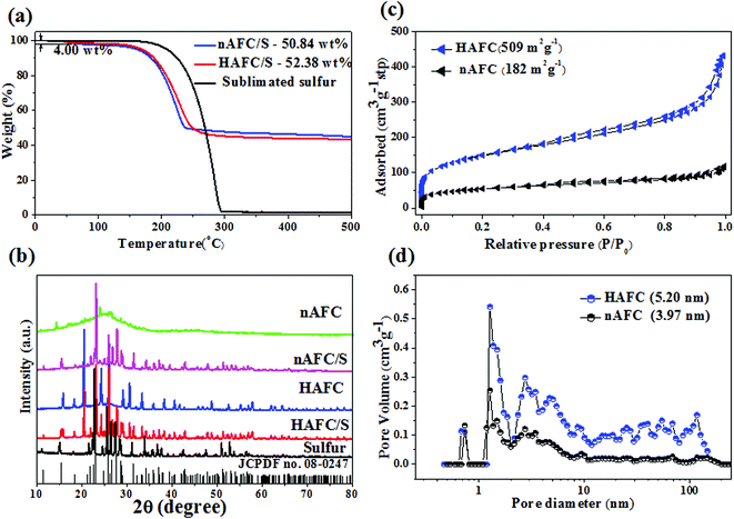
To detect the storing content of sulfur in the porous carbon, the thermal decomposition characteristics of HAFC/S and nAFC/S composites were investigated by TGA and the results are shown in Fig. 3a. As shown in Fig. 3a, the HAFC/S has a slight decline at the initial temperature of ∼60 °C due to water removal in the composite. With the temperature increasing, both HAFC/S and nAFC/S composites show weight loss at a temperature of 180 °C and maintain a continuous decline behavior until 300 °C. The sulfur content in HAFC/S and nAFC/S composites is 52.38 wt% and 50.84 wt%, respectively. The XRD patterns of standard pure sulfur (JCPDF no. 08-0247), sublimated sulfur, HAFC, nAFC, HAFC/S and nAFC/S materials are presented in Fig. 3b. The HAFC and nAFC materials show relatively broad diffraction peaks at ∼25° and 45°, which correspond to the diffraction of (002) and (001) planes of graphite, illustrating that the carbonized fungus has the typical structure of amorphous carbon.23,24 A series of characteristic peaks from 15 to 65° are found in HAFC, which may come from the phosphates.21,22 In HAFC/S and nAFC/S composites, the display of characteristic peaks of crystalline sulfur (JCPDF no. 08-0247) in 20–30° demonstrates the existence of sulfur in their composites. To explore the specific surface area and pore size distribution of nAFC and HAFC, the Brunauer–Emmett–Teller (BET) method was used to analyze them and the results are shown in Fig. 3c and d. In Fig. 3c, both nAFC and HAFC are similar to the type IV isotherm plots with characteristic hysteresis loops, indicating the existence of micro-/meso-pores at low relative pressure (0–0.2P/P0). The HAFC has a high surface area of 509 m2 g−1, while nAFC has a much smaller surface area of 182 m2 g−1, illustrating that the HAFC has more defects than nAFC, which can store more sulfur and restrict more polysulphides. Furthermore, the main pore size distributions of HAFC (3–12 nm) and nAFC (2–26 nm) in Fig. 3d also indicate that the HAFC has a strong interaction with sulfur under stem-melting behavior. After sulfur loading into the porous carbon, the surface area and pore volume of HAFC both decrease (Fig. S2†), which may indicate that the sulfur has been encapsulated into the micro/mesopores of this porous carbon. Therefore, the melting sulfur can be easily embedded into the mesopores due to the strong capillary force derived from nanopores.
In order to verify the chemical nature and the surface properties of the porous carbon/sulfur composite, X-ray photoelectron spectroscopy (XPS) measurements were carried out, and the results are displayed in Fig. 4. In the wide-survey XPS spectrum of HAFC/S composites (Fig. 4a), five distinct peaks centered at 284.6, 398.8, 533.2, 135.7 and 164.3 eV are equivalent to C 1s, N 1s, O 1s, P 2p and S 2p, respectively. As measured by XPS, the carbon, nitrogen, oxygen, phosphorus and sulfur contents in HAFC/S are 67.62 at%, 2.50 at%, 5.01 at%, 3.68 at% and 21.18 at%, respectively. The XPS results suggest that the nitrogen, phosphorus co-doped carbon material has been successfully fabricated in this work. The chemical status of C, N, P and S were further probed by analyzing the high-resolution C 1s, N 1s, P 2p and S 2p peaks. It can be seen that the high-resolution C 1s spectrum (Fig. 4b) of HAFC/S shows four peaks centered at 284.6, 284.9, 285.3 and 286.8 eV, corresponding to C–C/C![[double bond, length as m-dash]](https://www.rsc.org/images/entities/char_e001.gif) C (284.6 and 284.9 eV), C
C (284.6 and 284.9 eV), C![[double bond, length as m-dash]](https://www.rsc.org/images/entities/char_e001.gif) N/C–O/C–P (285.3 eV) and C
N/C–O/C–P (285.3 eV) and C![[double bond, length as m-dash]](https://www.rsc.org/images/entities/char_e001.gif) O/C–N (286.8 eV), respectively. For C–N/C
O/C–N (286.8 eV), respectively. For C–N/C![[double bond, length as m-dash]](https://www.rsc.org/images/entities/char_e001.gif) N bonds, the doped nitrogen atoms can be attributed to the four different existing states, which are pyridinic nitrogen (398.6 eV), pyrrolic nitrogen (400.1 eV), graphitic nitrogen (400.7 eV) and oxidized pyridinic nitrogen (401.9 eV), as shown in Fig. 4c, endowing the in situ dopant of N element in the fungus derived carbon material with excellent electrochemical performance towards the charge/discharge process. The P 2p deconvoluted peaks (Fig. 4d) located at 133.3 and 136.2 eV are all attributed to the contribution of P–O bonding, which is also responsible for the enhancement of the charge/discharge process. In particular, the high-resolution S 2p spectrum of HAFC/S can be deconvoluted into six peaks (Fig. 4e), which correspond to S–S/S–C bonds at 163.8, 164.2 and 164.7 eV, and sulfate species at 167.9, 169.1 and 169.5 eV. These nitrogen/phosphorus/oxidized-functional groups exist in the HAFC/S, which were reported to be attributed to the enhancement of the affinity and binding energy of polar polysulfides during the charge/discharge process, thus, remarkably improving the cycling stability and rate capability of lithium sulfur batteries.25–29
N bonds, the doped nitrogen atoms can be attributed to the four different existing states, which are pyridinic nitrogen (398.6 eV), pyrrolic nitrogen (400.1 eV), graphitic nitrogen (400.7 eV) and oxidized pyridinic nitrogen (401.9 eV), as shown in Fig. 4c, endowing the in situ dopant of N element in the fungus derived carbon material with excellent electrochemical performance towards the charge/discharge process. The P 2p deconvoluted peaks (Fig. 4d) located at 133.3 and 136.2 eV are all attributed to the contribution of P–O bonding, which is also responsible for the enhancement of the charge/discharge process. In particular, the high-resolution S 2p spectrum of HAFC/S can be deconvoluted into six peaks (Fig. 4e), which correspond to S–S/S–C bonds at 163.8, 164.2 and 164.7 eV, and sulfate species at 167.9, 169.1 and 169.5 eV. These nitrogen/phosphorus/oxidized-functional groups exist in the HAFC/S, which were reported to be attributed to the enhancement of the affinity and binding energy of polar polysulfides during the charge/discharge process, thus, remarkably improving the cycling stability and rate capability of lithium sulfur batteries.25–29
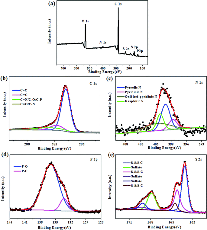 | ||
| Fig. 4 (a) XPS spectrum of the HAFC/S composite, and high-resolution spectra of C 1s (b), N 1s (c), P 2p (d) and S 2p (e) for the HAFC/S composite. | ||
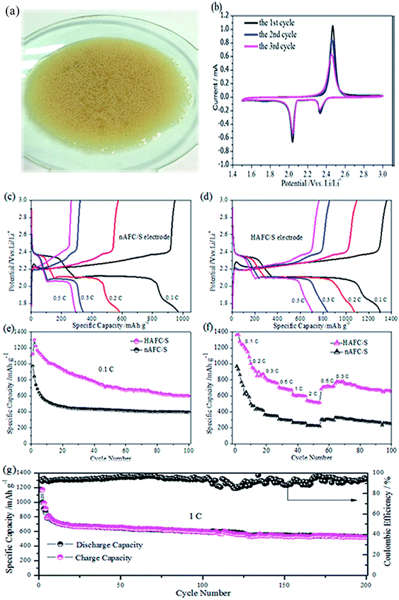
Fig. 5a presents the digital photo of many spherical conidia in culture medium. In the growth cycle, the fibroid fungus starts to develop on the conidia, which can gradually construct the interconnected framework (Fig. 2b) that can be carbonized to act as the sulfur host material in the cathode of lithium sulfur batteries. Hence, the carbon/sulfur electrodes are assembled in the battery to examine the electrochemical performances. Fig. 5b shows the first, second and third cyclic voltammogram curves of the HAFC/S electrode with a scanning rate of 0.1 mV s−1. During the first cathodic reduction process, two sharp reduction peaks at 2.32 and 2.08 V are displayed, which correspond to the reduction process of sulfur (S8) to soluble polysulfides (Li2Sn, 3 ≤ n ≤ 6) and then soluble polysulfides to the insoluble sulfides (Li2Sn, 1 ≤ n ≤ 2). An oxidation peak at 2.46 V is found in reverse scanning, which is related to the oxidation of Li2S2/Li2S to high-order LiPSs and the eventual transformation to elemental sulfur.30 Compared with the first CV curves, the positions of peaks on the second and third curves have no evident shift, indicating the outstanding reversibility of the fungus-derived carbon/sulfur electrode. Fig. 5c and d show the discharge/charge profiles of nAFC/S and HAFC/S electrodes at different current densities (0.1C, 0.2C, 0.3C, 0.5C, 1C and 2C), respectively. The profiles from the nAFC/S electrode present a shorter discharge plateau with the current rate increasing, which reflects the dissolution of various polysulfides in organic electrolyte. This leads to the loss of active sulfur and a low capacity acquisition. Unlike nAFC/S, the HAFC/S electrode has a longer discharge plateau, indicating that the effective utilization of active sulfur can induce a high discharge capacity. Even at high rates, the curves exhibit typical reaction plateaus, which are in coincidence with the cyclic voltammograms in Fig. 5b. Fig. 5e shows the cyclic performances of nAFC/S and HAFC/S electrodes at a low current density of 0.1C. Notably, the HAFC/S electrode exhibits a high initial capacity of 1319 mA h g−1 at 0.1C and maintains a capacity of 663 mA h g−1 after 100 cycles, illustrating the excellent cyclic performance of the HAFC/S electrode, while the nAFC/S electrode shows a low specific capacity of 985 mA h g−1 at 0.1C. A prolonged cycling test was also conducted for the HAFC/S electrode at 0.1C as shown in Fig. S3.† As displayed in the figure, a high initial capacity of 1225 mA h g−1 is obtained for the HAFC/S electrode at 0.1C. With continuous cycling, the capacity decreases due to the unavoidable “shuttle effect” that is caused by the dissolution of polysulfides derived from the surface sulfur. However, even the behavior of the dissolution of some polysulfides exists; the relatively large surface area and pore volume can also provide many active sites contributing to the high utilization of active sulfur and a specific capacity of 581 mA h g−1 after 200 cycles. The rate capabilities of the HAFC/S and nAFC/S electrodes were further investigated at different current rates from 0.1 to 2C, as shown in Fig. 5f. Despite the discharge specific capacity of the HAFC/S electrode gradually declining from 0.1 to 2C, a reversible capacity of 764 mA h g−1 for HAFC/S is recovered from the cathode when the current is switched back to 0.3C. From Fig. 5f, it can also be seen that the rate performance of HAFC/S is much better than that of nAFC/S due to the high utilization of sulfur and pore structure of the HAFC/S material. In order to examine the long-term cyclic stability, 200 cycles of the HAFC/S electrode at 1C were conducted, and the results are shown in Fig. 5g. The current density increases from 0.2C to 1C in the fifth cycle with the capacity of 720 mA h g−1. In the seasonable cycles, the capacity drops to 681 mA h g−1 and maintains a capacity of 495 mA h g−1 after 200 cycles with a columbic efficiency of 96%. It validates the good cyclic stability and reversibility of the HAFC/S electrode. All these outstanding electrochemical performances of the HAFC/S electrode can be attributed to the H3PO4 activated fibroid fungus, which possesses a high surface area and an appropriate nanopore size that can store sulfur and immobilize the various polysulphides dissolution during the cycles.
The coin cells are disassembled after 50 cycles to demonstrate the structural stability of the nAFC/S and HAFC/S electrodes. As shown in Fig. 6a1 and 6a2, the surface of nAFC/S was covered by the large gathered particles, which may be ascribed to the aggregation of lithium polysulfides. However, a relatively uniform, hierarchical porous structure of HAFC/S (Fig. 6b1 and 6b2) is still maintained after experiencing 50 cycles, suggesting that the porous structure can benefit from the encapsulation of polysulfides and decrease the loss of active sulfur, inducing outstanding electrochemical performance. The presence of uniform and small particles can be observed for the cycled HAFC/S electrode (Fig. 6c1 and 6c2), which indicates that the polysulfides have been restricted within the porosity of the HAFC material. All these characteristics are in coincidence with the electrochemical performance (Fig. 5).
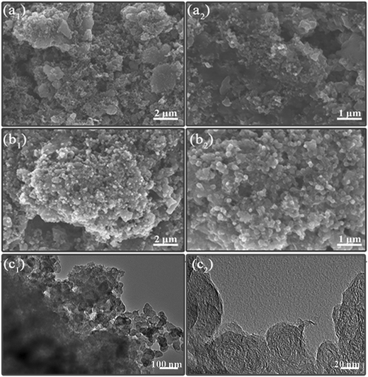 | ||
| Fig. 6 SEM images of cycled nAFC/S (a1, a2) and HEWC/S (b1, b2) electrodes, and TEM images of cycled HEWC/S (c1, c2) electrodes surface morphologies. | ||
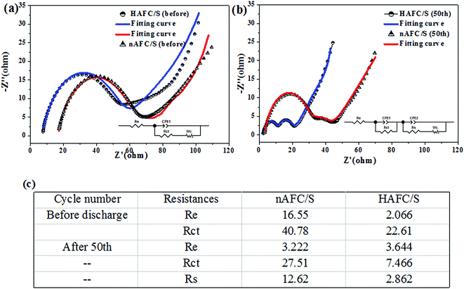
To better understand the improved electrochemical performance associated with the use of activated porous fungus carbon, electrochemical impedance spectroscopy (EIS) measurements were performed to explain the interfacial charge transfer and lithium-ion diffusion processes in HAFC/S and nAFC/S electrodes. As presented in Fig. 7a, the EIS spectra of the HAFC/S and nAFC/S electrodes both show a medium-to-high frequency semicircle and a long inclined line (Warburg impedance) in the low frequency region before discharging, while the two depressed semicircles and a short sloping line were displayed on the cycled electrode (Fig. 7b). Before discharging, the semicircle is attributed to the charge transfer process at the interface between the electrolyte and electrode, and the inclined line indicates the semi-infinite diffusion of soluble lithium polysulfide in the electrolyte.31,32 After the cycles, the two semicircles and the inclined plot are ascribed to the interfacial charge transfer process, the solid–electrolyte-interface (SEI) film and the related Warburg impedance, respectively. The correlated equivalent circuit models in the insets of Fig. 7a and b were used to analyze the impedance spectra, in which Re, Rct and Rs represent the electrolyte resistance, charge transfer resistance and the deposit diffusion resistance, respectively. As shown in Fig. 7c, the HAFC/S electrode has a smaller contact resistance (Re) and charge transfer resistance (Rct) than nAFC/S before the cycle, which may be ascribed to the high surface area and pore volume of HAFC that can benefit from the contact of insulating sulfur and the conductive carbon material. After 50 cycles, the charge transfer resistance (Rct) of the HAFC/S electrode still presents a relatively small value compared with the nAFC/S. It may be due to the dissolution of polysulfides into electrolyte that cause higher viscosity and lower Li+ ion mobility.
The electrolyte resistance of the HAFC/S electrode was increased from that before the cycle to the 50th cycle because of the dissolution of long-chain polysulfides in the electrolyte. Nevertheless, the charge resistance was decreased in comparison with that at the beginning, which may be attributed to the redistribution of active sulfur material in the HAFC matrix and the penetration of the electrolyte into the electrode.33,34 Furthermore, the relatively lower irreversible deposition and aggregation of insoluble Li2S and Li2S2 on the surface of the HAFC/S nanocomposite contributes to the transportation of Li-ions, which gets much easier as the cycle number increases and is beneficial for improving the rapid ions/electrons transfer that leads to the high rate capability of the cathode during long cycling.35,36
4. Conclusions
In this study, we have first cultivated the fibroid fungus by growing conidia on improved PDA medium. The stable period fungus was chosen to carbonize and obtain a novel, cauliflower-like shaped, porous carbon material with a relatively high surface area of 509 m2 g−1. The fungus-derived carbon material acts as the sulfur carrier in lithium sulfur batteries, and acquires a high initial specific capacity of 1319 mA h g−1 at 0.1C. Compared with such treatments as prevalent incineration and landfill, transforming by-products (fibrous fungus) derived from medical treatment into recyclable materials is more eco-friendly. Therefore, turning the wasted fibroid fungus to a carbon material by high temperature processing and its application in energy storage devices can be economical, environmentally-friendly and can show a promising application in electrochemical fields. Furthermore, the conductive current collector-free matrix derived from fibroid fungus applied in lithium sulfur batteries is underway.Conflicts of interest
The authors declare no competing financial interest.Acknowledgements
This study was supported by the projects of Sichuan Normal University (DJ GX2017017, DJ GX2017018 and DJ GX2017020) and the outstanding graduation thesis foundation of Sichuan Normal University (2017-17-31).References
- C. Guille and G. Gross, Energy Policy, 2009, 37, 4379 CrossRef.
- X. Yang, N. Yan, W. Zhou, H. Zhang, X. Li and H. Zhang, J. Mater. Chem. A, 2015, 3, 15314–15323 CAS.
- H. J. Peng, J. Q. Huang, M. Q. Zhao, Q. Zhang, X.-B. Cheng, X.-Y. Liu, W.-Z. Qian and F. Wei, Adv. Funct. Mater., 2014, 24, 2772–2781 CrossRef CAS.
- Y. Yang, G. Zheng and Y. Cui, Chem. Soc. Rev., 2013, 42, 3018–3032 RSC.
- X. L. Ji, K. T. Lee and L. F. Nazar, Nat. Mater., 2009, 8, 500 CrossRef CAS PubMed.
- N. Jayaprakash, J. Shen, S. S. Moganty, A. Corona and L. A. Archer, Angew. Chem., Int. Ed., 2011, 50, 5904 CrossRef CAS PubMed.
- C. Zhang, H. B. Wu, C. Yuan, Z. Guo and X. W. D. Lou, Angew. Chem., Int. Ed., 2012, 51, 9592 CrossRef CAS PubMed.
- T. Z. Hou, X. Chen, H. J. Peng, J.-Q. Huang, B.-Q. Li, Q. Zhang and B. Li, Small, 2016, 12, 3283–3291 CrossRef CAS PubMed.
- Z. Lin, Z. Liu, N. J. Dudney and C. Liang, ACS Nano, 2013, 7, 2829–2833 CrossRef CAS PubMed.
- J. Q. Huang, Q. Zhang, H. J. Peng, X. Y. Liu, W. Z. Qian and F. Wei, Energy Environ. Sci., 2014, 7, 347–353 CAS.
- R. Elazari, G. Salitra, Y. Talyosef, J. Grinblat, C. Scordilis-Kelley, A. Xiao, J. Affinito and D. Aurbach, J. Electrochem. Soc., 2010, 157, A1131–A1138 CrossRef CAS.
- C. Huang, J. Xiao, Y. Shao, J. Zheng, W. D. Bennett, D. Lu, S. V. Laxmikant, M. Engelhard, L. Ji, J. Zhang, X. Li, G. L. Graff and J. Liu, Nat. Commun., 2014, 5, 3015 Search PubMed.
- Y. S. Su and A. Manthiram, Nat. Commun., 2012, 3, 1166 CrossRef PubMed.
- Y. Fu, Y. S. Su and A. Manthiram, Angew. Chem., Int. Ed., 2013, 52, 6930 CrossRef CAS PubMed.
- J. Guo, Y. Xu and C. Wang, Nano Lett., 2011, 11, 4288 CrossRef CAS PubMed.
- H. Xu, Y. Deng, Z. Shi, Y. Qian, Y. Meng and G. Chen, J. Mater. Chem. A, 2013, 1, 15142 CAS.
- R. Yu, R. Li, Y. Tong, Y. Li, C. Li, J.-D. Hong and G. Shi, J. Mater. Chem. A, 2015, 3, 9609 Search PubMed.
- T.-M. Huggins, J.-M. Whiteley, C.-T. Love, K. Lee, S.-H. Lee, Z.-J. Ben and J.-C. Biffinger, ACS Appl. Mater. Interfaces, 2016, 8, 26868–26877M CAS.
- L.-Y. Zhang, Y. Wang, B. Peng, W.-T. Yu, H.-Y. Wang, T. Wang, B.-W. Deng, L.-Y. Chai, K. Zhang and J.-X. Zhang, Green Chem., 2014, 16, 3926–3934 RSC.
- H.-L. Wu, J.-R. Mou, L. Zhou, Q.-J. Zhen, N. Jiang and D.-M. Lin, Electrochim. Acta, 2016, 212, 1021–1030 CrossRef CAS.
- A.-M. Puziy, O. I. Poddubnaya, R.-P. Socha, J. Gurgul and M. Wisniewski, Carbon, 2008, 46, 2113 CrossRef CAS.
- A.-M. Puzii, Theor. Exp. Chem., 2011, 47, 277 CrossRef CAS.
- J. Chen, B. Yao, C. Li and G. Shi, Carbon, 2013, 64, 225 CrossRef CAS.
- S.-R. Zhao, C.-M. Li, W.-K. Wang, H. Zhang, M.-Y. Gao, X. Xiong, A.-B. Wang, K.-G. Yuan, Y.-Q. Huang and F. Wang, J. Mater. Chem. A, 2013, 1, 3334–3339 CAS.
- X. Zhou, F. Chen, J. Yang, L. Ma, T. Bai, B. Long, Q. Liao and C. Liu, J. Electroanal. Chem., 2015, 747, 59–67 CrossRef CAS.
- X. Zhou, F. Chen and J. Yang, J. Energy Chem., 2015, 24, 448–455 CrossRef.
- K. A. See, Y. S. Jun, J. A. Gerbec, J. K. Sprafake, F. Wudl, G. D. Stucky and R. Seshadri, ACS Appl. Mater. Interfaces, 2014, 6, 10908–10916 CAS.
- Q. Pang, J. Tang, H. Huang, X. Liang, C. Hart, K. C. Tam and L. F. Nazar, Adv. Mater., 2015, 27, 6021–6028 CrossRef CAS PubMed.
- G. Zhou, E. Paek, G. S. Hwang and A. Manthiram, Nat. Commun., 2015, 6, 7760 CrossRef CAS PubMed.
- M. Yu, J. Ma, M. Xie, H. Q. Song, F. Y. Tian, S. S. Xu, Y. Zhou, B. Li, D. Wu, H. Qiu and R. M. Wang, Adv. Energy Mater., 2017, 11, 1602347–1602358 CrossRef.
- W. G. Wang, X. Wang, L. Y. Tian, Y. L. Wang and S. H. Ye, J. Mater. Chem. A, 2014, 2, 4316–4323 CAS.
- W. Ahn, K.-B. Kim, K.-N. Jung, K.-H. Shin and C.-S. Jin, J. Power Sources, 2012, 202, 394–399 CrossRef CAS.
- Y. Cheng, S. Ji, X. Xu and J. Liu, RSC Adv., 2015, 121, 100089–100096 RSC.
- W. Weng, Q. Wu, Q. Sun, X. Fang, G. Z. Guan, J. Ren, Y. Zhang and H. S. Peng, J. Mater. Chem. A, 2015, 20, 10942–10948 Search PubMed.
- B. Ding, C. Z. Yuan, L. F. Shen, G. Y. Xu, P. Nie and X. G. Zhang, Chem.–Eur. J., 2013, 19, 1013–1019 CrossRef CAS PubMed.
- H. Wu, L. Xia, J. Ren, Q. Zheng, C. Xu and D. Lin, J. Mater. Chem. A, 2017, 5, 20458–20472 CAS.
Footnote |
| † Electronic supplementary information (ESI) available. See DOI: 10.1039/c7ra08501j |
| This journal is © The Royal Society of Chemistry 2017 |

