 Open Access Article
Creative Commons Attribution 3.0 Unported Licence
Orientation-dependent induced-charge electrophoresis of magnetic metal-coated Janus particles with different coating thicknesses†
Chia-Hsien Lin,
Yu-Liang Chen and
Hong-Ren Jiang*
Institute of Applied Mechanics, National Taiwan University, No.1, Sec. 4, Roosevelt Rd., Da'an Dist., Taipei City 106, Taiwan, Republic of China. E-mail: hrjiang@iam.ntu.edu.tw; d01543004@ntu.edu.tw
First published on 28th September 2017
Abstract
Orientation-dependent induced-charge electrophoresis (ICEP) behaviors are measured in magnetic metal-coated Janus particles, where the orientation of the particle with respect to the electric field is controlled by an external magnetic field. For a thin metallic coating (10 nm), the particle mainly moves normal to the electric field without the magnetic field. The velocities of ICEP in different directions are measured under the magnetic field and clear orientation-dependent velocities are observed. However, for a thick metallic coating (70 nm), the particle mainly moves parallel to the electric field without the magnetic field and shows an opposite tendency for orientation-dependent velocities compared with the thin metallic coated particles. We propose that the strength of the induced dipole of a Janus particle depends on the thickness of the metallic coating, which results in different orientation-dependent velocities of the Janus particle under electric fields.
1. Introduction
Active particles, which are known as particles that can convert energy from the environment into self-propulsion, arouse interest among scientists because of their interesting non-equilibrium transport phenomena1–3 and potential applications, such as micro-swimmers and use in drug delivery.4,5 Especially, electrokinetics is widely used to drive flows and manipulate colloids, including active particles, due to its accuracy and flexibility.6–11 Bazant et al. describe the flows resulting from the action of an applied electric field on its own induced charges around a polarizable structure as “induced-charge electro-osmosis” (ICEO), which is capable of driving Janus particles, whose surfaces have two or more distinct properties,12 under electric fields by “induced-charge electrophoresis” (ICEP).3,13–16 Janus particles driven by ICEP and the flow patterns of ICEO around the particles have been shown in different studies and become a promising field for designing small active components for different applications.3,17–20 However, the directly experimental data of particle velocity for ICEP and flow velocity for ICEO in orientation-dependence with respect to electric fields are seldom investigated by scientists. It would be useful if the properties of ICEP and ICEO can be dynamically tuned by orientations of induced dipole on polarizable objects. Recently, several studies suggest that the motion of magnetic Janus particles can be manipulated by coupling an external magnetic field and the other physical field.21–25 We propose that it should be possible to control the orientation of magnetic Janus particles under an electric field by applying an external magnetic field. In this study, we measure the orientation-dependent ICEP of Janus particles with different thicknesses of coating by applying both a parallel-coplanar electric field and a magnetic field. The orientation-dependent velocity of Janus particles in electric fields is experimentally observed.2. Experiment
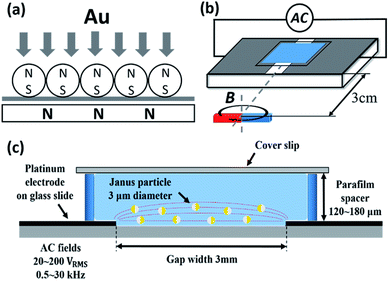
To prepare magnetic metal-coated Janus particles, a monolayer of 3 μm superparamagnetic polystyrene (PS) particles containing iron oxide nanoparticles (cat#86055, Polysciences) is prepared by a drying process (solvent evaporation) on the glass slide which is set on a static magnet, as shown in Fig. S1.†26 Because of the close packing of particles, one hemisphere of the particle is shaded, and only the other hemisphere is coated with metal.27,28 The magnetic dipole of a superparamagnetic PS particle can be aligned by the static magnet. Subsequently, the monolayer is putted into a sputter (JEOL, JFC-1100E) to coat with gold. Thus, the polarity of magnetic Janus particles is determined, which is N pole on the gold coated hemisphere and S pole on the dielectric side, as shown in Fig. 1(a). The sputtered gold thickness of Janus particles measured by an atomic force microscope (AFM) is from 10 nm to 75 nm depending on the sputtering time. A chamber containing a solution and Janus particles is sandwiched by a coverslip (top) and a pair of parallel–coplanar platinum electrodes (bottom) with a 120–180 μm spacer. The platinum electrodes are fabricated by sputtering. A tape with 3 mm width is attached on a glass slide and this slide is putted into the sputter to coat platinum for 200 s. The conductive layer (platinum) coated on the side measured by an AFM is about 35 nm. After coating process is completed, the tape is removed to form a 3 mm gap between a pair of electrodes. The electrodes are connected to a function generator and high voltage amplifier to apply a uniform AC electric field, the voltage of which varies from 20 to 200 VRMS and the frequency is from 0.5 to 30 kHz, Fig. 1(b) and (c). A magnet installed on a step motor is used to provide a magnetic field (<10 mT) in the arbitrary direction for manipulating the orientation of particles, Fig. 1(b). The two-dimensional trajectories of particles in the chamber are recorded by a CCD camera under an Olympus IX-70 inverted optical microscope through an object lens (20×, NA 0.5).3. Results and discussion
3.1 Thickness-dependency
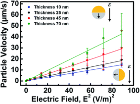
To verify the coating thickness-dependent ICEP behavior of Janus particles, the velocities of magnetic Janus particles with different coating thicknesses are experimentally measured under different strength of the electric field. The ICEP velocity increases with the square of the field strength, which is consistent with the previous studies,3,18,20 Fig. 2. In the case of Janus particles with a thin coating (10–25 nm), the ICEP motion of Janus particles is normal to the electric field with the dielectric hemisphere forward because of this orientation results in the largest induced dipole moment, which is aligned in the direction of the electric field.3 However, by increasing the coating thickness of Janus particles (45–70 nm), the ICEP motion becomes parallel to the electric field and the velocity also increasing with the coating thickness, as show in Fig. 2. This result indicates that the coating thickness dominates ICEP behavior resulting in different orientations of the ICEP motion. The velocities of Janus particles are also measured under distinct field frequencies. The velocities of Janus particles decrease with the frequency (ICEP motion) and even reverse at the high frequency region (>2 kHz), which is in accordance with previous studies (see ESI Fig. S2†).18,193.2 Orientation-dependency
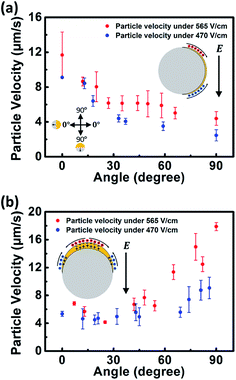
To investigate the orientation-dependent ICEP behavior of Janus particles, the velocities of magnetic Janus particles with different coating thicknesses are experimentally measured in the distinct azimuthal angle from 0° to 90° at field frequency of 1 kHz. When the polarity of the Janus particle directed from the Au side to the dielectric side is normal (parallel) to the direction of the electric field, the azimuthal angle is defined as 0° (90°), the left inset of Fig. 3(a). In general, the ICEP motion of Janus particles is normal to the electric field with the dielectric hemisphere forward because of this orientation results in the largest induced dipole moment, which is aligned in the direction of the electric field.3 In our experiments, the orientations of magnetic Janus particles are controlled by the external magnetic field and the magnetic torque acting on the particles is given by,| τ = mparticle × B | (1) |
 | (2) |
![[x with combining circumflex]](https://www.rsc.org/images/entities/i_char_0078_0302.gif) ) direction, βE is strength of electric field in the θ = π/2, ϕ = 0 (or ŷ) direction, ε is the permittivity, η is the viscosity of fluid, a is the particle radius, and δ is the ratio of the differential capacitances of the compact and diffuse layers. Thus, the ICEP velocity at the orientation which is normal to the field is given as, u⊥ = (9/64)(εaE2/η(1 + δ)), and the velocity at the orientation which is parallel to the field is given as, u∥ = (3/32)(εaE2/η(1 + δ)), which is 33% less than that at the orientation normal to the field. In the case of Janus particles with a thin Au coating (10 nm), the polarity of the Janus particle trends to align in the direction normal to the electric field. The ICEP velocity gradually decreases with altering azimuthal angles from 0° to 90° and is proportional to the square of field strength (not shown in the data), as shown in Fig. 3(a). According to previous studies, this tendency results from the variation of induced-charge distribution with the orientation of particle (from normal to the electric field to parallel to the field).16 However, from Fig. 3(a), the velocity at the orientation parallel to the field is 67% smaller than that at the orientation normal to the field. This could suggest that present ICEP theory for “dielectric coating” of the Janus particle can't satisfy the situation that a Janus particle made from a dielectric particle with half Au coating, commonly used in the experiments, moves in the direction parallel to the field due to lack of fully electric field screening ability comparing with the metal particle coated with a dielectric layer.27
) direction, βE is strength of electric field in the θ = π/2, ϕ = 0 (or ŷ) direction, ε is the permittivity, η is the viscosity of fluid, a is the particle radius, and δ is the ratio of the differential capacitances of the compact and diffuse layers. Thus, the ICEP velocity at the orientation which is normal to the field is given as, u⊥ = (9/64)(εaE2/η(1 + δ)), and the velocity at the orientation which is parallel to the field is given as, u∥ = (3/32)(εaE2/η(1 + δ)), which is 33% less than that at the orientation normal to the field. In the case of Janus particles with a thin Au coating (10 nm), the polarity of the Janus particle trends to align in the direction normal to the electric field. The ICEP velocity gradually decreases with altering azimuthal angles from 0° to 90° and is proportional to the square of field strength (not shown in the data), as shown in Fig. 3(a). According to previous studies, this tendency results from the variation of induced-charge distribution with the orientation of particle (from normal to the electric field to parallel to the field).16 However, from Fig. 3(a), the velocity at the orientation parallel to the field is 67% smaller than that at the orientation normal to the field. This could suggest that present ICEP theory for “dielectric coating” of the Janus particle can't satisfy the situation that a Janus particle made from a dielectric particle with half Au coating, commonly used in the experiments, moves in the direction parallel to the field due to lack of fully electric field screening ability comparing with the metal particle coated with a dielectric layer.27
To further verify the effect of thickness of coating, the motion Janus particles with a thick Au coating (70 nm) is measured at different orientations, which is mainly parallel to the electric field with the dielectric hemisphere forward without an external magnetic field. This could be elucidated by that, in the case of thick coating, the maximum induced dipole occurs in the direction parallel to the electric field, θ = 90°. By applying the magnetic field, the ICEP velocity gradually decreases with the azimuthal angle from 90° to 0°, as shown in Fig. 3(b). This result indicates that the strength of the induced dipole is the largest in the direction parallel to the electric field and decrease with azimuthal angle from 0° to 90°.
The maximum ICEP velocity of a Janus particle with a thin coating is at the orientation normal to the electric field. However, in the case of thick coating, the maximum ICEP velocity is at the orientation parallel to the electric field. Therefore, the prevalent theory for ICEP couldn't adequately describe the ICEP behaviors observed in our experiments. We propose that the induced dipole of a Janus particle, depending on the thickness of coating, dominates the ICEP behavior, including the ICEO flow pattern around the particle. For instance, the induced dipole of a Janus particle with a thin coating is the largest at the orientation normal to the electric field resulting in the maximum ICEP velocity and the symmetric ICEO flow driving the motion of the particle with the dielectric forward, as shown in the inset of Fig. 3(a). On the other hand, in the case of thick coating, induced dipole is the largest at the orientation parallel to the field and results in the maximum ICEP velocity in the same direction, inset of Fig. 3(b).
Due to the hemispherical coating feature of Janus particles, the length scale of coating thickness may become significant in polarization, which is similar to modifying the length scale of a different non-spherical object under an electric field. The electrokinetics of metal nanowires (rods) is reported in the previous studies.30,31 The induced dipole on a slender metal rod can be decomposed into the long and short axes components. The induced dipole along the long axis could be written as, pl = (4πεlh3Eh/3)(iΩ/(1 + iΩ![[thin space (1/6-em)]](https://www.rsc.org/images/entities/char_2009.gif) ln(1/β))) and along the short axis could be written as, ps = 4πεlrh2Er(iΩ − 1)/(iΩ + 1), where εl is the permittivity of liquid, h is the half length of the long axis, Eh and Er are the electric field along the long axis and short axis respectively, Ω is the non-dimensional frequency Ω = ωCDLr/σ, r is the half length of short axis, ω is the frequency of the electric field, σ is the liquid conductivity, C is the capacitance of the electrical double layer and β = r/h.31 The induced dipole on the slender metal rod depends on its geometry. Although the detailed analysis needs to be well constructed, the change of the coating thickness of Janus particle should alter the induced dipole and ICEP behavior of Janus particles.
ln(1/β))) and along the short axis could be written as, ps = 4πεlrh2Er(iΩ − 1)/(iΩ + 1), where εl is the permittivity of liquid, h is the half length of the long axis, Eh and Er are the electric field along the long axis and short axis respectively, Ω is the non-dimensional frequency Ω = ωCDLr/σ, r is the half length of short axis, ω is the frequency of the electric field, σ is the liquid conductivity, C is the capacitance of the electrical double layer and β = r/h.31 The induced dipole on the slender metal rod depends on its geometry. Although the detailed analysis needs to be well constructed, the change of the coating thickness of Janus particle should alter the induced dipole and ICEP behavior of Janus particles.
3.3 Orientation-dependent ICEO
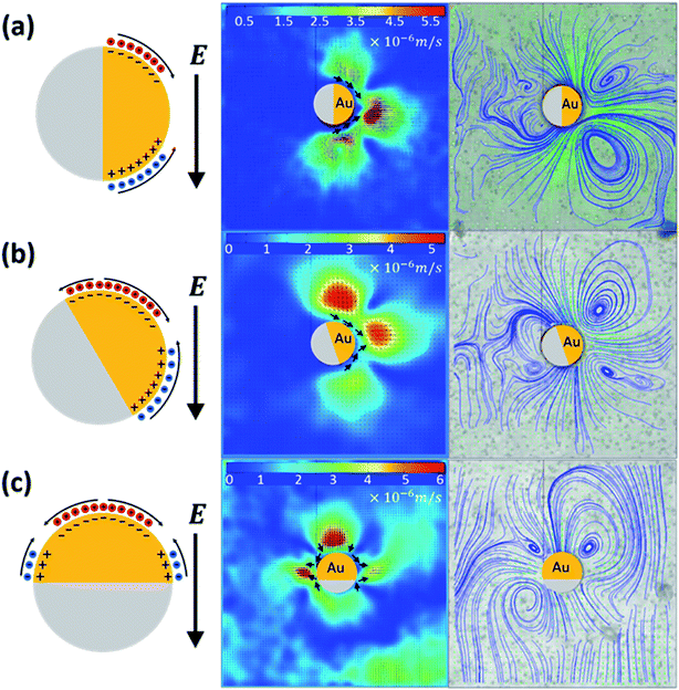
To investigate the dependence of ICEO flow pattern on the induced dipole, we directly measure and analyze the variation of the ICEO patterns around an immobilized particle with different orientations by a particle image velocimetry (PIV) software (Matlab, PIVlab). The flow patterns of ICEO at the orientation normal to and parallel to the electric fields have been reported by Chenhui Peng et al.17 In a polar coordinate, the velocity of ICEO is given as,6,15,16 uθ = (9a4/4η)(εaE2/1 + δ)cos![[thin space (1/6-em)]](https://www.rsc.org/images/entities/char_2009.gif) θ
θ![[thin space (1/6-em)]](https://www.rsc.org/images/entities/char_2009.gif) sin
sin![[thin space (1/6-em)]](https://www.rsc.org/images/entities/char_2009.gif) θ, on the metal side by Bazant et al. In our experiment, when the azimuthal angle is 0°, the flow pattern of ICEO around the particle is a pair of significant vortices near the Au hemisphere. The velocity near the Au side is higher than that near the dielectric side due to the higher polarizability of Au coating, as shown in Fig. 4(a). By turning the azimuthal angle to 15°, the up-down symmetry of ICEO is broken resulting in a stronger vortex near the top of Au side, as shown in Fig. 4(b). Finally, when the azimuthal angle is 90°, there are two pairs of vortices appearing. One is near the Au side, which could drive the particle with the dielectric forward, and the other is near the PS/Au interface, which could against particle moving, Fig. 4(c). The difference of the flow pattern results from the distinct distributions of the induced charges at the different orientations, as shown in the schematic drawings of Fig. 4. Note that the charge distributions in Fig. 4 are established based on the previous studies16 at different orientations of the Janus particle corresponding to a fixed electric field. This result also agrees with that the induced dipole dominates the ICEO flow around the particles.
θ, on the metal side by Bazant et al. In our experiment, when the azimuthal angle is 0°, the flow pattern of ICEO around the particle is a pair of significant vortices near the Au hemisphere. The velocity near the Au side is higher than that near the dielectric side due to the higher polarizability of Au coating, as shown in Fig. 4(a). By turning the azimuthal angle to 15°, the up-down symmetry of ICEO is broken resulting in a stronger vortex near the top of Au side, as shown in Fig. 4(b). Finally, when the azimuthal angle is 90°, there are two pairs of vortices appearing. One is near the Au side, which could drive the particle with the dielectric forward, and the other is near the PS/Au interface, which could against particle moving, Fig. 4(c). The difference of the flow pattern results from the distinct distributions of the induced charges at the different orientations, as shown in the schematic drawings of Fig. 4. Note that the charge distributions in Fig. 4 are established based on the previous studies16 at different orientations of the Janus particle corresponding to a fixed electric field. This result also agrees with that the induced dipole dominates the ICEO flow around the particles.
3.4 Trajectory control
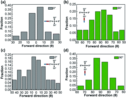
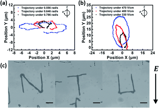
To investigate the stability of orientation-dependent ICEP motions, the magnet is place at the azimuthal angle 0° and 90°, respectively. In the thin coating case, the ICEP motion of Janus particles tends to normal to the electric field (along the azimuthal angle 0°). Thus, the distribution of the ICEP moving direction is more concentrated when the magnet is place at the azimuthal angle 0°, as shown in Fig. 5(a) and (b). On the other hand, in the thick coating case, the ICEP motion of Janus particles tends to parallel to the electric field (along the azimuthal angle 90°). The distribution of the ICEP moving direction is more concentrated when the magnet is place at the azimuthal angle 90°, as shown in Fig. 5(c) and (d). From Fig. 5, the ICEP trajectories of Janus particles aren't perfectly along the direction where the magnet is placed. This could result from the competition between the induced electric dipole and magnet dipole. Moreover, additional factors, such as surface roughness, contamination, and interaction with chamber wall, could result in the difference of the ICEP trajectory.17 The results from Fig. 5 further verify that the ICEP motion of Janus particles depends on the coating thickness of Janus particles.Finally, we demonstrate that the trajectories of Janus particles under an electric field are controlled by a rotating magnetic field. In the case of the thin Au coating, the trajectories are controlled by a rotating magnetic field with different rotational speeds at a constant strength of electric field of 530 V cm−1 and frequency of 1 kHz. The result is shown in Fig. 6(a). The trajectories are horizontally elliptical and the lengths of the trajectories are inversely proportional to rotational speed of the magnetic field. This further confirms that the Janus particle with the thin metal coating moves faster in the direction which is normal to the electric field. In the case of the thick Au coating, the trajectories are controlled with different strength of electric fields at a constant rotational speed of the magnetic field of 0.486 rad s−1 and frequency of 1 kHz. The trajectories are vertically elliptical and the lengths of the trajectories are proportional to the strength of electric field, which verifies that the particle with thick metal coating move faster in the direction which is parallel to the electric field, as shown in Fig. 6(b). Moreover, this study provides a programmable method to control the trajectory of magnetic Janus particles. A “NTU” logo is demonstrated by controlling the direction of the magnetic field, as shown in Fig. 6(c).
4. Conclusions
To conclude, we experimentally study the orientation-dependent ICEP behavior of the magnetic Janus particles with different coating thicknesses at the nanoscale, where the orientation of the particles with respect to the electric field can be dynamically tuned by an external magnetic field. According to our observation, the ICEP motion of Janus particles with thin coating is normal to the electric field. However, in the thick coating case, the ICEP motion is parallel to the electric field. We propose that the strength of induced dipole of a Janus particles, depending on the thickness of metallic coating at the nanoscale and orientation of a particle, dominates the behavior of ICEP. This study may bring new insights for induced-charge electrokinetic phenomena on widely used metal coated Janus particles and give a way to control and design active materials.Conflicts of interest
There are no conflicts to declare.Acknowledgements
We would like to acknowledge the members of our laboratory for fruitful discussions. This work is supported through the NSC 103-2112-M-002-008-MY3 grant funded by the Ministry of Science and Technology, Taiwan, R.O.C.References
- H.-R. Jiang, N. Yoshinaga and M. Sano, Phys. Rev. Lett., 2010, 105, 268302 CrossRef PubMed
.
- J. R. Howse, R. A. Jones, A. J. Ryan, T. Gough, R. Vafabakhsh and R. Golestanian, Phys. Rev. Lett., 2007, 99, 048102 CrossRef PubMed
.
- S. Gangwal, O. J. Cayre, M. Z. Bazant and O. D. Velev, Phys. Rev. Lett., 2008, 100, 058302 CrossRef PubMed
.
- Y. Wu, X. Lin, Z. Wu, H. Möhwald and Q. He, ACS Appl. Mater. Interfaces, 2014, 6, 10476–10481 CAS
.
- F. Mou, C. Chen, Q. Zhong, Y. Yin, H. Ma and J. Guan, ACS Appl. Mater. Interfaces, 2014, 6, 9897–9903 CAS
.
- A. Ramos, P. García-Sánchez and H. Morgan, Curr. Opin. Colloid Interface Sci., 2016, 24, 79–90 CrossRef CAS
.
- M. P. Hughes, Nanotechnology, 2000, 11, 124 CrossRef CAS
.
- K. H. Bhatt, S. Grego and O. D. Velev, Langmuir, 2005, 21, 6603–6612 CrossRef CAS PubMed
.
- D. Morganti, AC electrokinetic analysis of chemically modified microparticles, University of Southampton, 2012 Search PubMed
.
- T. B. Jones and T. B. Jones, Electromechanics of particles, Cambridge University Press, 2005 Search PubMed
.
- P. Sajeesh and A. K. Sen, Microfluid. Nanofluid., 2014, 17, 1–52 CrossRef
.
- A. Walther and A. H. Müller, Soft Matter, 2008, 4, 663–668 RSC
.
- M. Z. Bazant and T. M. Squires, Phys. Rev. Lett., 2004, 92, 066101 CrossRef PubMed
.
- T. M. Squires and M. Z. Bazant, J. Fluid Mech., 2004, 509, 217–252 CrossRef
.
- M. Z. Bazant, in Electrokinetics and Electrohydrodynamics in Microsystems, Springer, 2011, pp. 221–297 Search PubMed
.
- T. M. Squires and M. Z. Bazant, J. Fluid Mech., 2006, 560, 65–101 CrossRef
.
- C. Peng, I. Lazo, S. V. Shiyanovskii and O. D. Lavrentovich, Phys. Rev. E: Stat., Nonlinear, Soft Matter Phys., 2014, 90, 051002 CrossRef PubMed
.
- A. Boymelgreen, G. Yossifon and T. Miloh, Langmuir, 2016, 32, 9540–9547 CrossRef CAS PubMed
.
- R. Suzuki, H.-R. Jiang and M. Sano, arXiv preprint arXiv:1104.5607, 2011.
- Y. Daghighi, I. Sinn, R. Kopelman and D. Li, Electrochim. Acta, 2013, 87, 270–276 CrossRef CAS
.
- L. Baraban, D. Makarov, O. G. Schmidt, G. Cuniberti, P. Leiderer and A. Erbe, Nanoscale, 2013, 5, 1332–1336 RSC
.
- L. Baraban, D. Makarov, R. Streubel, I. Mönch, D. Grimm, S. Sanchez and O. G. Schmidt, ACS Nano, 2012, 6, 3383–3389 CrossRef CAS PubMed
.
- A. Ruditskiy, B. Ren and I. Kretzschmar, Soft Matter, 2013, 9, 9174–9181 RSC
.
- B. Ren, A. Ruditskiy, J. H. Song and I. Kretzschmar, Langmuir, 2011, 28, 1149–1156 CrossRef PubMed
.
- S. K. Smoukov, S. Gangwal, M. Marquez and O. D. Velev, Soft Matter, 2009, 5, 1285–1292 RSC
.
- Y. L. Chen and H. R. Jiang, J. Visualized Exp., 2017 DOI:10.3791/55950
.
- Y.-L. Chen and H.-R. Jiang, Appl. Phys. Lett., 2016, 109, 191605 CrossRef
.
- S. Ebbens, D. Gregory, G. Dunderdale, J. Howse, Y. Ibrahim, T. Liverpool and R. Golestanian, EPL, 2014, 106, 58003 CrossRef
.
- S. S. Shevkoplyas, A. C. Siegel, R. M. Westervelt, M. G. Prentiss and G. M. Whitesides, Lab Chip, 2007, 7, 1294–1302 RSC
.
- J. J. Arcenegui, P. García-Sánchez, H. Morgan and A. Ramos, Phys. Rev. E: Stat., Nonlinear, Soft Matter Phys., 2013, 88, 033025 CrossRef PubMed
.
- J. J. Arcenegui, P. García-Sánchez, H. Morgan and A. Ramos, Phys. Rev. E: Stat., Nonlinear, Soft Matter Phys., 2013, 88, 063018 CrossRef PubMed
.
Footnote |
| † Electronic supplementary information (ESI) available. See DOI: 10.1039/c7ra08527c |
| This journal is © The Royal Society of Chemistry 2017 |

