 Open Access Article
Creative Commons Attribution 3.0 Unported Licence
Direct catalytic effect of nitrogen functional groups exposed on graphenic materials when acting cooperatively with Ru nanoparticles†
Carolina Ramirez-Barriaab,
Cristina López-Olmosb,
Antonio Guerrero-Ruiz *ac and
Inmaculada Rodríguez-Ramos
 bc
bc
aDpto. Química Inorgánica y Técnica, Facultad de Ciencias UNED, Senda del Rey 9, 28040 Madrid, Spain. E-mail: aguerrero@ccia.uned.es
bInstituto de Catálisis y Petroleoquímica, CSIC, Cantoblanco, Marie Curie 2, 28049 Madrid, Spain
cUnidad Asociada UNED-ICP/CSIC Grupo de Diseño y Aplicación de Catalizadores Heterogéneos, Spain
First published on 15th September 2017
Abstract
A number of inorganic carbonaceous materials (activated carbon, high surface area graphite and graphenic materials) have been used as supports of Ru nanoparticles in order to determine their catalytic properties in the base-free aqueous-phase oxidation of 5-hydroxymethylfurfural (HMF) to 2,5-furandicarboxylic acid (FDCA). In particular, we have studied in detail reduced graphene oxide (rGO) and nitrogen doped reduced graphene oxide (NrGO), which are the support materials that produce more selective ruthenium catalysts. Also the effects of different metal precursors used in the preparation of the Ru nanocrystallites have been evaluated. Both support materials and Ru catalysts were characterized by elemental analysis, nitrogen physisorption (BET), thermogravimetric analysis (TGA), transmission electron microscopy (TEM), and X-ray photoelectron spectroscopy (XPS). The point of zero charge (PZC) for the graphenic materials was also determined. Interestingly the different supports significantly modify the catalytic performances, the graphenic materials being those that under our experimental reaction conditions produce the highest selectivity to FDCA. On these supports (rGO and NrGO) the highest HMF conversion was achieved by using triruthenium dodecacarbonyl as the ruthenium precursor. For the improved catalyst, Ru supported on NrGO, the yield of FDCA becomes close to 80%. This catalyst has been reused several times with neither loss of activity nor modification in selectivity values. Characterization data indicate these catalytic results can be correlated to the basic properties of the NrGO support as well as to the surface properties of Ru nanoparticles. These findings indicated that the metal precursor and the surface functional groups exposed on the support can modulate the catalytic properties, in particular amending the selectivity towards FDCA production.
Introduction
In the last few years there has been a growing interest in the conversion of renewable biomass resources into chemicals and fuels.1 In this context, HMF is a promising biomass-derived platform molecule generally produced through chemical dehydration of hexoses, such as glucose and fructose.2 The oxidation of HMF can generate several kinds of products such as 2,5-diformylfuran (DFF), 5-hydroxymethyl-2-furancarboxylic acid (HFCA), 5-formyl-2-furancarboxylic acid (FFCA) and 2,5-furandicarboxylic acid (FDCA) (Scheme 1). FDCA has been identified by the U.S. Department of Energy as one of the 12 top value added chemicals from biomass.3 FDCA can be used as an alternative monomer to potentially replace terephthalic acid which is involved in the production of polyethylene terephthalate (PET).4Several stoichiometric oxidants, such as HNO3, N2O4 and KMnO4,5 as well as homogenous catalytic systems6 have been used for the HMF oxidation into FDCA. However, harsh reaction conditions, corrosive properties of the media and production of large amounts of waste have a negative economic and environmental impact.
The oxidation of HMF to synthesize FDCA employing air or oxygen has been described along with different supported catalysts.7 Among the studied heterogeneous catalysts are noteworthy those based on noble metals such as Pt,8,9 Au,10,11 and Ru.12 However, it should be underlined that in most of the reported reaction procedures a base additive, essentially NaOH, KOH or Na2CO3, is required,13–15 so only very few works applying base-free catalysts have been reported.
Casanova et al.16 claimed a useful strategy to avoided base added requirement, using methanol as solvent instead of water. Using an Au/CeO2 catalyst under oxygen pressure, 2,5-dimethylfuroate is the main product. Despite its outstanding activity and selectivity, the oxidation of the solvent was unavoidable due to it follows a similar oxidation pathway than the substrate.
Highly basic solid supports have also been proposed as replacements of the base during HMF oxidation in water. Gupta and coworkers17 reported Au nanoparticles supported on hydrotalcite (HT) to catalyze the aqueous-phase oxidation of HMF to FDCA showing good performances. However, later studies18 suggested that alkali contaminants from the synthesis of the HT supports or co-existing partially soluble brucite favored the results obtained. Along the same lines, high yields of FDCA were also obtained by Gorbanev et al.19 using Ru(OH)X supported on a HT and MgO. Nevertheless, extensive deactivation due to leaching of magnesium from both supports is taking placed. In recent publications Au–Pd alloys20 and Pt21 supported on functionalized carbon nanotubes (CNT) were presented as base-free alternatives in the aerobic oxidation of HMF to FDCA under oxygen pressure. It is reported that the oxygen-containing functional groups, in particular carbonyl/quinone and/or phenol groups, on CNT surfaces play crucial roles in FDCA formation. These functional groups could enhance the adsorption of HMF as well as the reaction intermediates from water and might facilitate hydrogen transfer. Nonetheless, long reactions times of 12 and 14 h respectively were required besides the use of expensive metals as Au, Pt and Pd. Also, the facet effect and size-dependent effect of single-crystalline Pd nanocrystals on the aerobic oxidation of HMF has been systematically investigated by experimental and theoretical approaches.22 It was found that the size-dependent effect of these Pd nanocrystals derived from the different surface Pd atom percentages. So, Pd atoms at (111) facets exhibited notably enhanced catalytic activity for the aerobic oxidation of HMF than Pd atoms at (100) facets. By controlling the amount of surface Pd atoms to be identical, Pd nanocrystals with the same shape but different particle sizes exhibited very similar catalytic performances for HMF oxidation. Ruthenium catalysts supported on carbon materials were studied by Yi et al.,23 however very high metal![[thin space (1/6-em)]](https://www.rsc.org/images/entities/char_2009.gif) :
:![[thin space (1/6-em)]](https://www.rsc.org/images/entities/char_2009.gif) HMF ratios are required to achieve significant catalytic yield to FDCA.
HMF ratios are required to achieve significant catalytic yield to FDCA.
Due to the lack of more economically attractive and stable heterogeneous catalyst systems, we propose the development of new nanomaterials, consisting of nitrogen doped graphene and small Ru crystallites, which must be efficient and stable when acting as heterogeneous catalysts for the aerobic oxidation of HMF into FDCA in the water media. Moreover we aim to work under base-free conditions taking advantage of the surface functional groups incorporated in the support material. Also we are using for this study Ru based catalysts, as this metal is cheaper than Au, Pd and Pt.24
Special consideration will be paid to the effect induced by the surface functional groups exposed at the surfaces of graphenic materials, such as, nitrogen groups which have been reported previously by our group as basic ingredient of catalysts.25 More precisely, it has been demonstrated that the incorporation of N into these graphenic materials improves their chemical and electrical properties. It is due to the fact that N presence improves electronic density of the carbon material incorporating by one more electron into the carbon surface becoming more basic.26 This possibility of acting on the carbon surface properties and the high specific surface area of graphenic materials, make them highly promising materials. So, recently de Jongh et al.11 reported that Au nanoparticles are affected by the presence of surface oxygen groups exposed on high surface area graphite when used in the HMF oxidation, but the reaction experiments were carried out in the presence of NaHCO3 solved in the media. Also in a recent review article27 has been remarked the interest in controlling and applying the functionalization of graphene materials. However, to the best of our knowledge, there is no report on the using of nitrogen doped graphene materials as support for the base free oxidation of HMF. Herein, we comparatively investigate the preparation and characterization of Ru based catalysts supported on carbonaceous materials as activated carbon, high surface area graphite, graphenic materials. These catalytic materials have been applied in the base-free oxidation of HMF in water to yield FDCA, aiming to achieve higher reaction yields at moderate reaction conditions (temperature and time in reaction).
Experimental
Preparation of supports
Graphenic materials were obtained via thermal treatment of graphite oxide (GO). GO was synthesized from natural graphite powder (325 mesh) supplied by Alfa Aesar (purity 99.8%) following a modification of the Brodie's method.28 This procedure is as follows: 10 g of graphite (G) were added to 200 mL of fuming HNO3 kept at 0 °C in the reaction flask. 80 g of KClO3 were slowly added during 2 hours. Thereafter, the mixture was stirred for 21 h maintaining the temperature. The resulting GO was filtered and washed thoroughly with deionized water until neutral pH. The sample was dried overnight at 100 °C. Exfoliation of the synthesized GO was carried out in a vertical quartz reactor under inert and reactive atmospheres. Two exfoliation conditions have been applied. One where GO was heated under nitrogen (87 mL min−1) until 700 °C (yielding rGO) while for the second consists in passing a mixture of NH3, H2 and N2 with flow rates of 10, 3 and 87 mL min−1 while the temperature increased up to 700 °C with a heating rate of 10 °C min−1 (giving NrGO). Apart from the lab prepared graphenic materials a commercial activated carbon (AC, provided by Oleicola el Tejar, Córdoba Spain, SBET = 1190 m2 g−1, 313 m2 g−1 external surface area) and a high surface area graphite (HSAG 400, from TIMCAL, SBET = 396 m2 g−1) were also employed as support of Ru metallic nanoparticles.Preparation of catalysts
All supported Ru catalyst were prepared in order to obtain samples with ruthenium loading of 4 wt%. Three different precursors were used in the catalyst preparation. Ru3(CO)12 (catalyst series denoted with “CO”) was incorporated in the supports by wetness impregnation, once dissolved the exact amount in acetone. The solvent was removed under reduced pressure on a rotary evaporator at about 50 °C during at least 30 minutes. Before characterization and catalytic tests these materials were treated under hydrogen flow (60 mL min−1) at 350 °C for 2 h, in order to decompose the precursor and assure their initial metallic state. Two other series of Ru catalyst were prepared, using RuCl3 as precursor (series denoted as “Cl”) or using Ru(NO)(NO3)3 (series labelled with “NN”). For these two series the graphenic materials were impregnated by incipient wetness method. The metal precursors were dissolved, in both cases, into a water![[thin space (1/6-em)]](https://www.rsc.org/images/entities/char_2009.gif) :
:![[thin space (1/6-em)]](https://www.rsc.org/images/entities/char_2009.gif) ethanol (1
ethanol (1![[thin space (1/6-em)]](https://www.rsc.org/images/entities/char_2009.gif) :
:![[thin space (1/6-em)]](https://www.rsc.org/images/entities/char_2009.gif) 1) solution. After evaporation of solvent by keeping the solids overnight in an open recipient at room temperature, the samples were dried at 100 °C for 24 h. Finally the catalysts were activated by reduction under hydrogen flow as indicated before. Once the reduced samples are at room temperature a helium flow (50 mL min−1) is passed for 5 h in order to passivate the metallic surfaces. The reduced/passivated catalysts were exposed and stored under air up to their evaluation in reaction or the characterization studies.
1) solution. After evaporation of solvent by keeping the solids overnight in an open recipient at room temperature, the samples were dried at 100 °C for 24 h. Finally the catalysts were activated by reduction under hydrogen flow as indicated before. Once the reduced samples are at room temperature a helium flow (50 mL min−1) is passed for 5 h in order to passivate the metallic surfaces. The reduced/passivated catalysts were exposed and stored under air up to their evaluation in reaction or the characterization studies.
Material characterizations
The chemical analysis (C, H and N) of the supports was performed using a Perkin-Elmer elemental analyzer. The textural characterization and surface area (SBET) determinations were obtained from the nitrogen adsorption (−196 °C) isotherms, which were obtained using a Micromeritics ASAP model 2020 instrument. To obtain the point of zero charge (PZC) of graphenic materials, the electrophoretic mobility (μ) vs. pH of the samples was measured in a Zeta Meter 3.0+ at 25 °C. PZC was determined following the experimental procedure described in detail elsewhere.29 Transmission Electron Microscopy (TEM) micrographs of the supports and of the catalysts were obtained on a JEOL JEM-2100F microscope at 200 kV. The samples were ultrasonically suspended in ethanol before deposition over a carbon-coated copper grid of 200 mesh. The average metal particle sizes in the catalysts were calculated using the following formula:30where ni is the number of particles with diameter di.
The samples were also analysed by X-ray diffraction (XRD), using a Polycristal X'Pert Pro PANalytical diffractometer with Ni-filtered Cu/K radiation (λ = 1.54 Å) operating at 45 kV and 40 mA. For each sample, Bragg's angles between 4° and 90° were scanned at a rate of 0.04° s−1. Thermal analysis were also recorded in TG/DTA mode in a TA Instruments SDT Q600 under air. All the catalysts were analysed by X-ray photoelectron spectroscopy (XPS) using an SPECS GmbH with UHV system, energy analyzer PHOIBOS 150 9MCD using a monochromatic X-ray source of Al Kα (1486.74 eV). Each sample was pressed into a small pellet of 10 mm diameter, placed in the sample holder and degassed in the chamber for 24 h to achieve a dynamic vacuum below 10−10 mbar before analysis. The catalysts were first activated by reduction in H2 flow (70 mL min−1) at 400 °C during 1 h in the sample pretreatment chamber. The spectral data for each sample were analyzed using CASA XPS software. The C 1s peak at 284.6 eV was used as an internal standard. The equipment error in the energy determinations is less than 0.01 eV.
Reactivity measurements
The oxidation of 5 HMF was carried out using an autoclave (Autoclave Engineers) reactor with 150 mL capacity, equipped with a mechanical stirrer (500 rpm) and furnace system. By some preliminary studies using the same catalyst it was determined that under this stirring velocity there is not intern mass transfer limitations. After reduction treatment, the catalysts (50 mg) were suspended in 100 mL of water. Then the autoclave was purged three times with synthetic air and the temperature was increased to 100 °C. Once the reaction conditions were reached, 1 mL of HMF 0.2 M in H2O was dosed into the autoclave and pressure was raised up to 10 bars with air. Aliquots of the reactor liquids were collected periodically, filtered and the reaction product mixture was analysed by HPLC (Agilent Technologies 1200 series equipped with a refractive index detector, Hi-Plex H column, flow 0.7 mL min−1, mobile phase 5 mM H2SO4, temperature 65 °C). Carbon mass balances in the reaction studies are higher than 94% in all the catalytic determinations. Some of these experiments were repeated twice in order to check reproducibility of these measurements.The conversion of HMF was calculated as:
The selectivity of each product was calculated as:
Site time yields (STY), moles of FDCA produced per mol of catalyst surface per second, were also calculated. For determine the active surface area exposed by the Ru nanocrystallites we have assumed perfectly spherical metallic shapes. Thus with the direct measured of the diameters of such as metallic particles by TEM it is possible to determine the numbers of exposed active sites.
Results and discussion
Characteristics of the supports
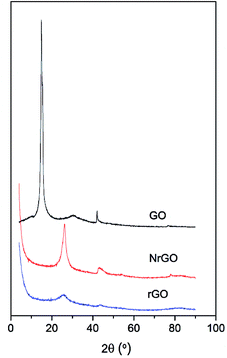
Fig. 1 shows the XRD patterns of GO, rGO and NrGO. After thermal treatment, the characteristic diffraction peak at 16° of GO disappeared and a new main peak appeared at 26° corresponding to the graphite (002) reflection.25 The GO was successfully exfoliated to form NrGO and rGO materials. However, the more intense peak at 26° for NrGO may indicate some restacking of graphene layers. The comparison of this peak for NrGO and rGO samples evidenced that restacking is favored under ammonia reactive conditions. It was also confirmed by SBET values, so SBET of rGO (904 m2 g−1) is higher than that measured for NrGO (483 m2 g−1) and the degree of restacking should decrease the surface area of graphenic material.25 This is consistent with TEM images (Fig. S1 in ESI†) where it can be observed that graphitic structures appear in the case of NrGO, while rGO solid consists of few layer graphene.The concentration of nitrogen adatoms in the graphenic supports was determined by elemental analysis. As expected, no nitrogen is detected in rGO. The N content for NrGO was 4.6 wt%. Furthermore, XPS analyses for the NrGO sample showed nitrogen content of 3.8 wt% suggesting a somewhat lower concentration of nitrogen species at surface. Deconvolution of the N 1s region (Fig. S2 in ESI†) indicated the presence of four nitrogen species: 41% pyridinic nitrogen (398.5 eV), 27% pyrrolic nitrogen (400.5 eV), 18% quaternary nitrogen (401.8 eV), and 14% NOx groups (405.0 eV).31 Among all these species, the pyridinic nitrogen is believed to have the stronger basic character. Accordingly, it is generally assumed that the basicity of carbon catalysts is linked to the amount of pyridinic groups.32,33 No nitrogen peak was detected for rGO.
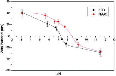
As the surface charge of carbonaceous materials is governed by the nature of the surface groups and the pH, PZC can be used to estimate the surface chemistry of the graphenic materials.34 An increase in the PZC value was found for NrGO sample (Fig. 2) showing a PZC of 8.5 against 7.2 of rGO sample. These results indicate that NrGO surfaces present a greater basic character than rGO. Since nitrogen atoms have an additional electron in comparison with carbon atoms, p electron delocalization will occur easily in NrGO. This excess of electrons produces an increase in the electronic density, which could explain the higher PZC values obtained for NrGO. As electron-donor properties are related to basicity, the stronger the electron donating is, the greater the basicity.31 Finally PZC measurements carried out on the reduced catalysts (i.e. samples Ru(CO)/rGO and Ru(CO)/NrGO) do not provide significant differences in comparison with the bare supports. This mean that the possible Ru anchoring over the surface nitrogen groups cannot be detected from the PZC determinations.
The thermal reactivity under air of the prepared supports was investigated by TGA (Fig. S3 ESI†). TG analysis for rGO showed a sharp weight loss near 628 °C that could be attributed to the oxidation of a well-organized carbon structure. In comparison, sample NrGO showed an oxidation temperature of 671 °C, which is in concordance with previously reported trends35 showing that the thermal stability in air increases for nitrogen doped graphenic materials.
Characteristics of the Ru nanoparticles
The loading of Ru in carbon supported metal catalyst was estimated by TGA. Thermogravimetric method consisted in weighing the residues of RuO2 generated after burning away the graphenic support at 850 °C in air.36 Also it was checked that bare supports (rGO and NrGO) produce null amount of residue. The same can be said for the HSAG support material. Contrarily in the case of the commercial CA, in spite of its purification treatment, a small residue weight was determined (0.24 wt%), this amount being subtracted for determining the quantitative loading of incorporated Ru. Considering the similarities of the nominal amount of Ru incorporated and the experimental determinations, we can point out that Ru is not volatilized under these carbon support burning conditions. The chemical compositions of the catalyst are presented in Table 1.| Catalyst | Ru (wt%) | dTEM (nm) |
|---|---|---|
| Ru(Cl)/rGO | 3.9 | 1.5 |
| Ru(Cl)/NrGO | 4.4 | 2.1 |
| Ru(NN)/rGO | 4.0 | 1.4 |
| Ru(NN)/NrGO | 4.0 | 1.7 |
| Ru(CO)/rGO | 4.3 | 1.4 |
| Ru(CO)/NrGO | 3.9 | 1.8 |
| Ru(CO)/AC | 4.1 | 2.4 |
| Ru(CO)/HSAG | 4.1 | 2.3 |
The XRD patterns of the catalysts prepared from different ruthenium precursors are shown in Fig. 3. All the samples showed the characteristic (002) reflection of graphitic carbon at 26° (discussed above). However, no peaks related with the formation of crystalline Ru were observed on the samples. This is surely due to the particle size of Ru-NPs in these samples was below the XRD detection threshold as was evidenced in the dTEM values reported in Table 1. Finally the addition of metal seems not to change significantly the peak intensity at 26 degree, so the initial structures graphenic or graphitic seems not to be modified by the incorporation of the Ru nanoparticles.
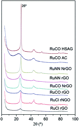 | ||
| Fig. 3 XRD patterns of Ru(Cl)/rGO, Ru(Cl)/NrGO, Ru(NN)/rGO, Ru(NN)/NrGO, Ru(CO)/rGO, Ru(CO)/NrGO, Ru(CO)/AC and Ru(CO)/HSAG after H2 reduction at 350 °C. | ||
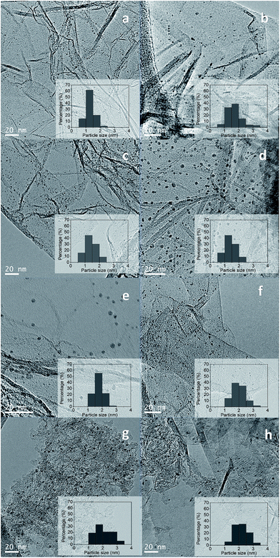
The particle sizes of the ruthenium crystallites exposed in the reduced catalysts were determined by TEM. Representative TEM images of the catalysts and their histograms with particle size distribution are shown in Fig. 4.
The Ru nanoparticles average size obtained for the carbon supported catalysts are summarized in Table 1. The average ruthenium particle sizes for these catalysts are in the range from 1.4 to 2.4 nm. From Table 1 it should be noted that the particle size of Ru nanoparticles strongly depends from the Ru precursor and the used support. Comparison of catalysts supported on the two graphene supports (rGO and NrGO) for a given Ru precursor reveals that larger particle sizes were systematically obtained on NrGO support, which can be rationalized in terms of the lower specific surface area of the NrGO support regarding rGO support. When a graphene support (rGO or NrGO) is considered the ruthenium particle size change with the metal precursor in the order: Ru(Cl) > Ru(NN) ≈ Ru(CO). As shown in Fig. 4 Ru nanoparticles were dispersed uniformly on graphene surfaces without detecting aggregation formation, so the interactions of graphene surfaces with the Ru crystallites seem to be maximized. On the other hand, there are not evidences of any association of the Ru nanoparticles with the N atoms of the NrGO support, and these nitrogen functionalities seem not to play any role in determining the Ru crystallite sizes. In general mean Ru particle sizes (Table 1) are higher in the catalysts supported over NrGO than in those supported over rGO. The diameter size distribution histograms of these catalysts are displayed in Fig. 4. It is observed that the particle size distribution is broadened when the NrGO is used as support with respect to rGO. Moreover, Ru(CO)/HSAG and Ru(CO)/AC catalysts present the highest average particle size and also the broadest particle size distribution. This is likely consequence of the lower surface area of HSAG (396 m2 g−1) and AC (313 m2 g−1 external surface area) compared to rGO (904 m2 g−1) and NrGO (483 m2 g−1).
XPS analysis was done in order to study the electronic states of Ru nanoparticle on the different catalysts. Due to the binding energy of Ru 3d3/2 overlapped partially with that of C 1s, Ru 3p signal was used to distinguish the chemical states of Ru samples. The Ru 3p XPS spectrum for Ru(Cl)/NrGO catalyst showed two peaks centered at 462.7 eV and 484.7 eV corresponding to Ru 3p3/2 and Ru 3p1/2 respectively (Table 2 and Fig. 5a). Notably, the peaks for Ru(Cl)/NrGO appeared at lower binding energy compared to Ru(Cl)/rGO peaks (463.0 eV and 485.0 eV in Table 2). The latter fact suggests that the incorporation of nitrogen atoms in the graphitic structure of graphene could favor donation of electron density towards Ru active sites. More significantly some residual chlorine impurities on the surface were observed in the survey scan XPS spectrum of Ru(Cl)/NrGO and Ru(Cl)/rGO catalysts. However some similar shifts in the Ru binding energies towards lower energy values were observed when compared with Ru(CO)/NrGO and Ru(NN)/NrGO catalysts (Table 2 and Fig. S4†). That we can conclude that when the Ru nanoparticles are supported over the nitrogen-doped graphenic material there is a systematic electronic interaction between this support and the Ru nanoparticles with electron transfer from the support to the Ru. In agreement with our results an earlier work of X. Chen et al.37 reported that the N-doped graphene is an effective electron donor for iron nanoparticles as revealed by Fe K-edge XANES study.
| Catalyst | BE Ru 3p3/2 (eV) | FWHM | Ru/C |
|---|---|---|---|
| Ru(Cl)/rGO | 463.0 | 2.4 | 0.001 |
| Ru(Cl)/NrGO | 462.7 | 3.1 | 0.002 |
| Ru(NN)/NrGO | 462.5 | 3.6 | 0.004 |
| Ru(CO)/NrGO | 462.4 | 3.5 | 0.005 |
Catalytic results
Previous research with different metals (Ru, Pt) and supports (oxidic and carbonaceous materials),19,21 demonstrates both the relevance of the support in the achieved final FDCA yield (Scheme 1), and that in general carbon supports are superior.Table 3 lists the results of the base-free aqueous-phase oxidation of HMF to FDCA over the supported Ru catalysts prepared from different precursors. First, blank tests were carried out, without catalyst addition in the reactor, and barely formation of products was observed (entry 1 Table 3). Also the bare supports give very low HMF conversions (entries 2 and 3) under our reaction conditions. From Table 3 it can be observed that the achieved HMF conversions with nearly all the Ru studied catalysts were higher than 97.5% after 8 h in reaction. Concerning the selectivity values significant differences can be observed depending on precursor and support. For instance when Ru nanoparticles are supported on commercial carbons (Ru(CO)/HSAG and Ru(CO)/AC) FDCA selectivity values are significantly lower than when supported on graphenic materials. For Ru(CO)/AC and Ru(CO)/HSAG catalysts the poor catalytic selectivities towards FDCA can be attributed to the Ru average particle sizes, 2.3 nm and 2.4 nm respectively (Table 1), which are significantly higher than the sizes in Ru catalysts supported on graphene supports (rGO and N-rGO), in particular than those prepared with Ru carbonyl as metal precursor. Apparently an increased average metal particle size implies a reduction in the reaction rate since the progress of the consecutive oxidation reactions to reach the desired FDCA product is slower.
| Entry | Catalyst | Conversion (%) | Sel FDCA (%) | Sel FFCA (%) | Sel DFF (%) |
|---|---|---|---|---|---|
| 1 | Blank | 1.6 | 0.0 | 0.0 | 100.0 |
| 2 | NrGO | 4.2 | 0.0 | 16.5 | 83.5 |
| 3 | rGO | 2.7 | 0.0 | 0.0 | 100 |
| 4 | Ru(Cl)/rGO | 99.1 | 49.4 | 47.5 | 3.1 |
| 5 | Ru(Cl)/NrGO | 97.5 | 43.1 | 48.0 | 8.8 |
| 6 | Ru(NN)/rGO | 100.0 | 75.8 | 24.2 | 0.0 |
| 7 | Ru(NN)/NrGO | 99.1 | 81.5 | 18.0 | 0.5 |
| 8 | Ru(CO)/rGO | 100.0 | 79.6 | 20.4 | 0.0 |
| 9 | Ru(CO)/NrGO | 100.0 | 79.1 | 20.9 | 0.0 |
| 10 | Ru(CO)/HSAG | 99.3 | 40.5 | 53.6 | 5.9 |
| 11 | Ru(CO)/AC | 99.2 | 39.0 | 59.0 | 2.1 |
The selectivities toward FDCA obtained with catalysts prepared from RuCl3 precursor over graphenic materials were also lower than selectivity values obtained with Ru3(CO)12 and Ru(NO)(NO3)3 derived catalysts. The presence of chlorine impurities, that was confirmed by XPS as it was discussed above, can be the reason of this different behavior. This poisoning of the Ru nanoparticles38 and a possible increase of acidity due to the presence of chlorine ions, seems to be responsible for the low selectivity towards FDCA of Ru(Cl)/rGO and Ru(Cl)/NrGO catalysts.
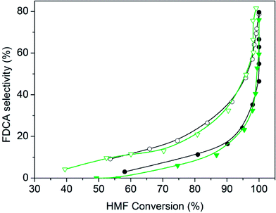
For catalysts prepared with both Ru3(CO)12 and Ru(NO)(NO3)3 precursors, higher selectivity towards FDCA was found when supported on NrGO in comparison with those supported on rGO. In Fig. 5 the evolution of selectivity towards FDCA as the reaction is progressing is represented. Clearly a systematic support effect is evidenced. For these four catalysts, with Ru average particle sizes among 1.4 nm and 1.8 nm, as reported in Table 1, the possible effect of the nitrogen surface groups can be neatly evidenced. The single most noteworthy observation from these comparative data was that HMF could be completely converted, and with 79.1% selectivity towards FDCA, over Ru(CO)/NrGO after 8 h at 100 °C (entry 9).
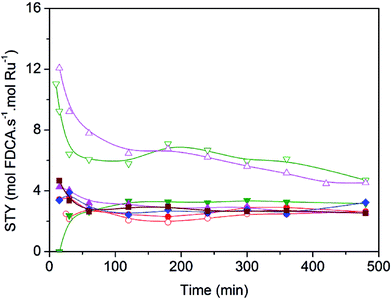
In order to quantitatively compare the effects induced by the presence of nitrogen surface groups in the graphenic materials when used as supports, in Fig. 6 catalyst activity is reported for each catalyst as site time yield (STY), moles of FDCA produced per mol of surface Ru per second. Clearly the two Ru catalysts supported on Nr-GO produce, in all the range of reaction time, higher selectivity values towards FDCA formation than those supported on rGO. This effect is observable for the two series of catalysts: ex-nitrosyl nitrate and ex-carbonyl. As reported in Table 3, entries 2 and 3, the bare support NrGO produce significant higher amount of FFCA in comparison with rGO, in spite of the low HMF conversion (Table 3). This FFCA is an intermediated in the formation of FDCA (Scheme 1).
Therefore, all these results would seem to indicate the nitrogen functional groups significantly affect in the NrGO supported Ru catalysts, improving the selectivity to FDCA. The nature of the nitrogen effect could be thought to be twofold. On the one hand, the basic sites, as evidenced from PZC (Fig. 2), in the case of Ru catalysts supported on NrGO, surely may contribute to the reaction in synergy with the Ru nanoparticles. However, the electron enrichment of the Ru nanoparticles, observed by XPS measurements, which could affect their activity for the HMF oxidation, can not improve the activity for the oxidation reaction, because a higher electron density of the surface Ru would disfavor both the dioxygen dissociation and the HMF chemisorption. Thus our main hypothesis is that basic sites, in the case of Ru nanoparticles supported on NrGO, surely may contribute to the reaction in synergy with the Ru nanoparticles. In short the combination of very small Ru crystallites with some basic surface functions can act cooperatively. In a first stage oxygen and reactant are chemisorbed on the Ru surface and the production of acidic compounds (HFCA, FFCA and FDCA) starts. When FDCA is formed this is more efficiently removed from the metallic surface in the presence of basic sites exposed on the graphenic materials. These mechanistic aspects have been outlined in the Scheme 2, and should be considered as an explanation of the results presented in Fig. 5 and 6. So, this mechanism is close to that taking place when a basic compound is dissolved in the reaction media: reaction equilibrium displacement by elimination of the products from the proximity of the active surface sites. We can define this mechanism action as a cooperative effect between the surface sites exposed on the Ru nanoparticles and those basic functionalities exhibited on the nitrogen doped graphenic material (NrGO).
 | ||
| Scheme 2 Proposal for the cooperative action of the nitrogen surface groups exposed on the doped graphenic materials and the Ru nanoparticles. | ||
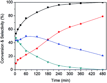
A representative example of the time course of the conversion (%) of HMF to the reaction products (%), determined using the Ru(CO)/NrGO catalyst, are presented in Fig. 7. During the first 15 minutes, the main product was DFF. As HMF was consumed, the yield of DFF decreased and the yield of FFCA increased. The yield of the intermediates decreased and the yield of FDCA increased up to near 79% at 8 hours. Furthermore no HMFCA formation was detected. On the basis of these results we proposed that under our experimental conditions FDCA is produced by a stepwise reaction via DFF and FFCA as shown Scheme 1. This tendency is in good agreement with previous studies21 in the base-free oxidation of HMF. It is also worth noting that 85% of HMF is converted in the first two hours showing that the steps HMF to DFF and FFCA are faster than the reaction of transformation of FFCA into FDCA. Therefore, Ru catalyzed the oxidation of –OH to –CHO, and further oxidized to –COOH, this latter being the rate-limiting step.
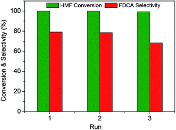
In order to evaluate the stability of this Ru(CO)/NrGO catalytic material, three successive rounds were carried out with the solid recovered by filtration and washed with water. As shown in Fig. 8, the initial conversion of HMF was maintained for at least three runs. However, the selectivity of FDCA slightly decreased during the recycle process. It could be related to a small loss of mass during recovery of the catalyst between cycles and/or with a blocking of the support basic surface sites by some adsorbed reaction products. Finally the concentration of potentially leached ruthenium in the aqueous solution was analysed by inductively coupled plasma mass spectrometer (ICP-MS). For post-reaction solutions obtained from the Ru(CO)/NrGO catalyst after the three stability runs, no ruthenium was detected. This absence of Ru leaching can be rationalized considering that before reaction tests catalysts were subjected to a reduction pretreatment at 350 °C, and the resulting metallic Ru particles are no soluble in water media. Thus all these results demonstrated the outstanding stability and reusability of our improved Ru(CO)/NrGO catalyst.
In order to compare our best performance catalysts with those previously published, in Table 4 are reported data obtained using different noble metal catalysts supported over diverse supports. It should be notice that in any case presented data are obtained using added base as co-catalyst and in all the reactions presented in Table 4 water is the solvent media. So these reported data are obtained under the greenest conditions. The comparison among catalysts in Table 4 is not easy since the reaction variables, such as temperature, pressure, reaction time or molar reactant-metal ratio, are not identical. However, our Ru catalysts are similar in terms of activity and selectivity to those reported in the literature containing noble metals (Au, Pt) which are more expensive than Ru. When comparing with Ru catalysts supported on different materials, our samples result slightly superior, just considering that we work at lower reaction temperature and pressure.
| Catalyst | HMF![[thin space (1/6-em)]](https://www.rsc.org/images/entities/char_2009.gif) : :![[thin space (1/6-em)]](https://www.rsc.org/images/entities/char_2009.gif) M ratio M ratio |
T (°C) | O2 pressure (bar) | Time (h) | Conversion (%) | FDCA selectivity (%) | Reference |
|---|---|---|---|---|---|---|---|
| 19Au/HT | 40 | 95 | 1 | 7 | 100 | 99 | 17 |
| 2.4Ru/HT | 20 | 140 | 2.5 | 6 | 100 | 95 | 19 |
| 2.4Ru/MgO | 20 | 140 | 2.5 | 6 | 100 | 92 | |
| 2.4Ru/CeO2 | 20 | 140 | 2.5 | 6 | 100 | 30 | |
| 1Au–1Pd/CNT | 100 | 100 | 5 | 12 | 100 | 94 | 20 |
| 1Au–1Pd/CNT | 100 | 100 | 10 bar air | 12 | 100 | 96 | |
| 1Au–1Pd/CNT Ptto H2O2 | 100 | 100 | 5 | 12 | 100 | 95 | |
| 1Au–1Pd/HT | 100 | 100 | 5 | 12 | 100 | 91 | |
| 5Pt/CNT | 100 | 95 | 5 | 14 | 100 | 98 | 21 |
| 5Ru/CNT | 100 | 95 | 5 | 14 | 47 | 2 | |
| 5Pt/HT | 100 | 95 | 5 | 14 | 100 | 97 | |
| 5Pt/GO | 100 | 95 | 5 | 14 | 100 | 95 | |
| 5Pt/CNT Ptto HNO3 | 100 | 95 | 5 | 14 | 100 | 98 | |
| 432Ru/CTF-a | 40 | 140 | 20 bar air | 1 | >99 | 38 | 39 |
| 5 mol% Ru/C | 10 | 120 | 5 | 10 | 100 | 88 | 23 |
| Pt/C–O–Mg (HCl washed MgO–C) | 50 | 110 | 10 | 12 | >99 | 96 | 40 |
| Pt/MgO–C | 50 | 110 | 10 | 12 | >99 | 96 | |
| Ru(CO)/NrGO | 10 | 100 | 10 bar air | 8 | 100 | 79 | Present |
| Ru(NN)/NrGO | 10 | 100 | 10 bar air | 8 | >99 | 82 | Work |
Conclusions
Ru catalysts prepared using different metal precursors (nitrosyl nitrate, carbonyl and chloride) and supported over various carbonaceous materials (high surface area graphite, activated carbon, graphene and N-doped graphene) were studied in the aqueous-phase aerobic oxidation of HMF. The reported data of selectivity cannot be only explained as consequence of Ru particle sizes, as evidenced by the similar average particle sizes determined by TEM (in the range between 1.4 and 2.4 nm). The obtained results suggest that the support along with the Ru precursor remarkably affect the product distributions and surface properties of the ruthenium nanoparticles over the supports. In particular graphenic materials are superior in comparison with commercial carbonaceous materials. Significantly it was revealed that basic surface nitrogen heteroatoms exposed on the NrGO support can play an important role, particularly in the desired product selectivity. As tentative interpretation of this systematic support effect we have argued that Ru nanoparticles supported on nitrogen doped graphene can act synergistically with the basic surface nitrogen sites exposed on the doped graphene surface. These latter can remove the acidic products of this reaction cooperating with the maintenance of free surface Ru sites to perform the oxidation reaction more rapidly.Conflicts of interest
There are no conflicts to declare.Acknowledgements
CRB gratefully acknowledges financial support from Spanish Ministerio de Educacion, Cultura y Deporte Grant No. FPU15/01838. Also the financial support from the Spanish Ministerio de Economía y Competitividad under projects CTQ2014-52956-C3-2-R and CTQ2014-52956-C3-3-R is recognized.Notes and references
- M. J. Climent, A. Corma and S. Iborra, Green Chem., 2014, 16(2), 516–547 RSC.
- J. N. Chheda, G. W. Huber and J. A. Dumesic, Angew. Chem. Int. Ed., 2007, 46(38), 7164–7183 CrossRef CAS PubMed.
- T. Werpy and G. Petersen, Top Value Added Chemicals from Biomass, 2004, vol. 1 Search PubMed.
- R. A. Sheldon, Green Chem., 2014, 16(3), 950–963 RSC.
- T. Miura, H. Kakinuma, T. Kawano and H. Matsuhisa. Method for producing furan-2,5-dicarboxylic acid, US pat., 7411078B2, 2008.
- W. Partenheimer and V. V. Grushin, Adv. Synth. Catal., 2001, 343(1), 102–111 CrossRef CAS.
- Z. Zhang and K. Deng, ACS Catal., 2015, 5(11), 6529–6544 CrossRef CAS.
- P. Vinke, H. E. Van Dam and H. Van Bekkum, Stud. Surf. Sci. Catal., 1990, 55(8), 147–158 CrossRef CAS.
- M. a Lilga, R. T. Hallen and M. Gray, Top. Catal., 2010, 53(15–18), 1264–1269 CrossRef CAS.
- O. Casanova, S. Iborra and A. Corma, ChemSusChem, 2009, 2(12), 1138–1144 CrossRef CAS PubMed.
- B. Donoeva, N. Masoud and P. E. de Jongh, ACS Catal., 2017, 7, 4581–4591 CrossRef CAS.
- J. Xie, J. Nie and H. Liu, Chin. J. Catal., 2014, 35(6), 937–944 CrossRef CAS.
- A. a. Rosatella, S. P. Simeonov, R. F. M. Frade and C. A. M. Afonso, Green Chem., 2011, 13(4), 754 RSC.
- S. Albonetti, A. Lolli, V. Morandi, A. Migliori, C. Lucarelli and F. Cavani, Appl. Catal., B, 2015, 163, 520–530 CrossRef CAS.
- F. Neaţu, R. S. Marin, M. Florea, N. Petrea, O. D. Pavel and V. I. Pârvulescu, Appl. Catal., B, 2016, 180, 751–757 CrossRef.
- O. Casanova, S. Iborra and A. Corma, J. Catal., 2009, 265(1), 109–116 CrossRef CAS.
- N. K. Gupta, S. Nishimura, A. Takagaki and K. Ebitani, Green Chem., 2011, 13(4), 824 RSC.
- L. Ardemani, G. Cibin, A. J. Dent, M. A. Isaacs, G. Kyriakou, A. F. Lee, C. M. A. Parlett, S. A. Parry and K. Wilson, Chem. Sci., 2015, 6(8), 4940–4945 RSC.
- Y. Y. Gorbanev, S. Kegnæs and A. Riisager, Top. Catal., 2011, 54(16–18), 1318–1324 CrossRef CAS.
- X. Wan, C. Zhou, J. Chen, W. Deng, Q. Zhang, Y. Yang and Y. Wang, ACS Catal., 2014, 4(7), 2175–2185 CrossRef CAS.
- C. Zhou, W. Deng, X. Wan, Q. Zhang, Y. Yang and Y. Wang, ChemCatChem, 2015, 7(18), 2853–2863 CrossRef CAS.
- D. Lei, K. Yu, M.-R. Li, Y. Wang, Q. Wang, T. Liu, P. Liu, L.-L. Lou, G. Wang and S. Liu, ACS Catal., 2017, 7(1), 421–432 CrossRef CAS.
- G. Yi, S. P. Teong and Y. Zhang, Green Chem., 2016, 18(4), 979–983 RSC.
- F. F. Tao, Metal Nanoparticles for Catalysis: Advances and Applications, ed. F. Tao, The Royal Society of Chemistry, Cambridge, 2014 Search PubMed.
- E. Asedegbega-Nieto, M. Perez-Cadenas, M. V. Morales, B. Bachiller-Baeza, E. Gallegos-Suarez, I. Rodriguez-Ramos and A. Guerrero-Ruiz, Diamond Relat. Mater., 2014, 44, 26–32 CrossRef CAS.
- E. Castillejos-Lopez, B. Bachiller-Baeza, E. Asedegbega-Nieto, A. Guerrero-Ruiz and I. Rodriguez-Ramos, RSC Adv., 2015, 5(99), 81583–81598 RSC.
- G. Bottari, M. Á. Herranz, L. Wibmer, M. Volland, L. Rodríguez-Pérez, D. M. Guldi, A. Hirsch, N. Martín, F. D'Souza and T. Torres, Chem. Soc. Rev., 2017, 46, 4464–4500 RSC.
- B. C. Brodie, Philos. Trans. R. Soc. London, 1859, 149(9), 249–259 CrossRef.
- C. Ramirez-Barria, A. Guerrero-Ruiz, E. Castillejos-Lopez, I. Rodríguez-Ramos, J. Durand, J. Volkman and P. Serp, RSC Adv., 2016, 6(59), 54293–54298 RSC.
- E. Gallegos-Suarez, M. Perez-Cadenas, A. Guerrero-Ruiz, I. Rodriguez-Ramos and A. Arcoya, Appl. Surf. Sci., 2013, 287, 108–116 CrossRef CAS.
- L. Faba, Y. a. Criado, E. Gallegos-Suarez, M. Pérez-Cadenas, E. Díaz, I. Rodriguez-Ramos, A. Guerrero-Ruiz and S. Ordóñez, Appl. Catal., A, 2013, 458, 155–161 CrossRef CAS.
- S. Van Dommele, K. P. de Jong and J. H. Bitter, Chem. Commun., 2006, 76(46), 4859–4861 RSC.
- B. Li, X. Sun and D. Su, Phys. Chem. Chem. Phys., 2015, 17, 6691–6694 RSC.
- P. Serp and J. L. Figueiredo, Carbon Materials for Catalysis, ed. P. Serp and J. L. Figueiredo, John Wiley & Sons, Inc, New Jersey, 2008 Search PubMed.
- R. Canty, E. Gonzalez, C. MacDonald, S. Osswald, H. Zea and C. C. Luhrs, Materials, 2015, 8(10), 7048–7058 CrossRef PubMed.
- A. Guerrero-Ruiz, P. Badenes and I. Rodríguez-Ramos, Appl. Catal., A, 1998, 173(2), 313–321 CrossRef CAS.
- X. Chen, D. Deng, X. Pan, Y. Hu and X. Bao, Chem. Commun., 2015, 51(1), 217–220 RSC.
- a. Guerrero-Ruiz, E. Gallegos-Suarez, L. Gonzalo-Chacon and I. Rodriguez-Ramos, Thermochim. Acta, 2013, 567, 112–117 CrossRef CAS.
- J. Artz and R. Palkovits, ChemSusChem, 2015, 8(22), 3832–3838 CrossRef CAS PubMed.
- X. Han, L. Geng, Y. Guo, R. Jia, X. Liu, Y. Zhang and Y. Wang, Green Chem., 2016, 18, 1597–1604 RSC.
Footnote |
| † Electronic supplementary information (ESI) available: Fig. S1 contains TEM micrographs of the different graphenic supports, Fig. S2 contains XPS spectra of the N 1s region for NrGO, Fig. S3 contains TGA for graphenic supports and Fig. S4 XPS spectra of the Ru 3p region of Ru(Cl)/rGO and Ru(Cl)/NrGO catalysts. See DOI: 10.1039/c7ra08774h |
| This journal is © The Royal Society of Chemistry 2017 |


