 Open Access Article
Creative Commons Attribution 3.0 Unported Licence
High performance nano-sized LiMn1−xFexPO4 cathode materials for advanced lithium-ion batteries†
Zhihong Lei a,
Ahmad Naveeda,
Jingyu Leia,
Jiulin Wang
 *a,
Jun Yang
 a,
Yanna Nulia,
Xiangchen Mengb and
Yunliang Zhaob
aDepartment of Chemical Engineering, Shanghai Electrochemical Energy Devices Research Centre, Shanghai Jiao Tong University, Shanghai 200240, PR China. E-mail: wangjiulin@sjtu.edu.cn
bSong Yuan Power Supply Company, Jilin Electric Power Co. LTD, Jilin 138000, PR China
First published on 11th September 2017
Abstract
A series of LiMn1−xFexPO4 (0 ≤ x ≤ 1) cathode materials with different Mn/Fe ratios have been successfully synthesized by a facile solvothermal method. LiMn1−xFexPO4/C nanoparticles have a width of ca. 50 nm and a length of 50–200 nm, coating with a thin carbon layer (ca. 2 nm). The effects of iron content on the series of LiMn1−xFexPO4/C materials have been systemically investigated. The homogeneous solid solution and highly conducting nanostructure lead to excellent specific capacities, superior discharge rate capabilities and energy densities for x values in the range of 0.2–0.3. For example, LiMn0.7Fe0.3PO4/C can deliver discharge capacities of 167.6, 153.9 and 139.1 mA h g−1 at 0.1C, 1C, and 5C rate, respectively, and shows excellent cycle stability at different rates, and can be considered as a cathode candidate for practical application in advanced lithium-ion batteries.
Introduction
Lithium metal phosphates are promising polyanion cathode materials for lithium-ion batteries, owing to their inherent merits such as low cost, decent electrochemical properties, high stability and environmental benignity. However, these merits have often been undermined by insufficient energy and power delivery due to the extremely low conductivity of phosphates at room temperature and poor Li+ intercalation/deintercalation kinetics.1,2By doping, carbon coating and nano-sized morphology design, the olivine LiFePO4 (LFP) cathode material has been utilized in power batteries for electric vehicles/hybrid electric vehicles in modern society. Due to its higher potential plateau of 4.1 V vs. Li/Li+ as compared with LFP (3.45 V), olivine LiMnPO4 (LMP) possesses a 20%-higher theoretical energy density than LFP. Moreover, it matches the stability window of conventional carbonate ester-based electrolytes. However, LMP suffers from the drawbacks with even lower intrinsic electronic conductivity (<10−10 S cm−1) than those of LFP (>10−8 S cm−1) and Jahn–Teller lattice distortion at Mn3+ sites, thus leading to lower specific capacity and poorer cycle ability.3–7
Up to now, various strategies have been adopted in efforts to promote the electrochemical performance of LMP, such as strict carbon coating, minimizing particles size, and Mn-site substitution. Substituting the Mn site with Fe has been found to be extremely effective for improving the electrochemical performance.8–10 Various LiMn1−xFexPO4 materials have been reported and the effect of iron substitution is proven.11–17 For examples, Damen et al. reported that LiMn1−xFexPO4 (x = 0, 0.2, 0.3) materials were prepared via sol–gel, pyrolysis and ball milling steps, in which LiMn0.8Fe0.2PO4 showed the largest discharge capacity of 135 mA h g−1 at 0.1C at 50 °C.18 Hong et al. synthesized LiMn1−xFexPO4 (x = 0, 0.1, 0.2) nanomaterials via a facile solvothermal route in a mixed solvent of water and polyethylene glycol (PEG200) wherein LiMn0.8Fe0.2PO4 sample demonstrated the highest discharge capacity of ca. 135 mA h g−1 at 0.5C.19 Liao et al. reported that LiFe0.15Mn0.85PO4/C material exhibited the best performance and delivered discharge capacities of 163.1 mA h g−1 at 0.1C and 150.3 mA h g−1 at 1C in a series of LiFexMn1−xPO4/C (x ≤ 0.15) materials which were synthesized by solvothermal reactions in ethylene glycol mixed solutions.20 A facile polymer-assisted mechanical activation was used to prepare LiMn1−xFexPO4 (0 ≤ x ≤ 1) by Xiao et al. wherein Mn rich LiMn0.75Fe0.25PO4 could deliver 157 mA h g−1 at 0.1C.21 Traditional solid state reaction was also tried to synthesize a series of LiFe1−xMnxPO4 materials by Zhang et al. in which LiMn0.7Fe0.3PO4 exhibited a highest discharge capacity of 130 mA h g−1 at 0.1C.22
Although the investigation on LiMn1−xFexPO4/C materials has achieved a great progress, the available capacity under high rate is still unsatisfactory. The electrode kinetics should be improved. In this work, a series of LiMn1−xFexPO4 (0 ≤ x ≤ 1) nanomaterials have been successfully synthesized by the solvothermal method, using a new solution system. In addition, a thin carbon layer (ca. 2 nm) was further coated on the surface of LiMn1−xFexPO4. Effect of the iron substitution and Mn/Fe ratio on the crystal structure, morphology and electrochemical performance are investigated and discussed in detail. Based on the facile synthetic technology and the excellent electrochemical performance, our work may widen the potential application of LiMn1−xFexPO4 cathode material for advanced lithium-ion battery.
Experimental
Preparation of materials
LiMn1−xFexPO4 (LMFP) (x = 0, 0.05, 0.10, 0.15, 0.20, 0.25, 0.30, 0.40, 0.50, 1) were prepared by a facile solvothermal method. Stoichiometric amounts of manganese sulfate monohydrate (MnSO4·H2O), ferrous sulfate (FeSO4·7H2O) and ammonium dihydrogen phosphate (NH4H2PO4) were dissolved in distilled water and mixed. Ascorbic acid was dispersed in distilled water, then added into the former solution directly as a reducing agent under stirring. N,N′-Dimethylformamide was added carefully. Then lithium hydroxide solution [molar ratio of Li/Mn/Fe = 3![[thin space (1/6-em)]](https://www.rsc.org/images/entities/char_2009.gif) :
:![[thin space (1/6-em)]](https://www.rsc.org/images/entities/char_2009.gif) (1 − x)
(1 − x)![[thin space (1/6-em)]](https://www.rsc.org/images/entities/char_2009.gif) :
:![[thin space (1/6-em)]](https://www.rsc.org/images/entities/char_2009.gif) x] were dripped slowly and high speed stirring was kept for about 2 h at room temperature to form a gray suspension. The final suspension was sealed into Teflon-lined stainless steel autoclave and heated in an oven at 180 °C for 12 h. After the vessel was cooled down to room temperature, a black reacted suspension was centrifuged at 10
x] were dripped slowly and high speed stirring was kept for about 2 h at room temperature to form a gray suspension. The final suspension was sealed into Teflon-lined stainless steel autoclave and heated in an oven at 180 °C for 12 h. After the vessel was cooled down to room temperature, a black reacted suspension was centrifuged at 10![[thin space (1/6-em)]](https://www.rsc.org/images/entities/char_2009.gif) 000 rpm for ten minutes and washed several times with deionized water. The claybank powders of LMFP were obtained and dried in vacuum oven at 80 °C.
000 rpm for ten minutes and washed several times with deionized water. The claybank powders of LMFP were obtained and dried in vacuum oven at 80 °C.
The LMFP sample was ground to fine powder. 20 wt% sucrose (suc) was mixed with LMFP powder in appropriate ethanol, milled with a high speed of 350 rpm for 6 h (Fritsch, Germany). Afterwards, the mixture was annealed at 550 °C for 4 h in an Ar/H2 atmosphere (Ar/H2 = 95![[thin space (1/6-em)]](https://www.rsc.org/images/entities/char_2009.gif) :
:![[thin space (1/6-em)]](https://www.rsc.org/images/entities/char_2009.gif) 5, v/v). Finally, the black LiMn1−xFexPO4/C materials were obtained.
5, v/v). Finally, the black LiMn1−xFexPO4/C materials were obtained.
Structure and morphology characterization
The phase compositions of cathode materials were characterized by powder X-ray diffraction analysis (XRD, Bruker D8 Advance) with Cu Kα radiation, operating at 40 kV × 40 mA with scanning rate of 0.25° min−1 or 6° min−1. Rietveld refinement was carried out by GSAS software package.23 Inductively coupled plasma (ICP, Thermo fisher Scientific iCAP7600) atomic emission spectrometry analysis was used to analyze the elemental composition of Li, Mn, Fe and P. The morphologies were observed using a field emission scanning electron microscope (FESEM, HITACHI S-4800). And the fine structure of materials were observed by a high resolution transmission electron microscope (HRTEM, JEOL 2100F). The carbon contents in the samples were measured by equipment of high frequency infrared ray carbon sulfur analyzer (CS-206 Shanghai Baoying). The electronic conductivities were measured at room temperature by four-probe dc technique (RTS-8, Guangzhou 4 probes). Cylindrical pellets with diameter of 12 mm of synthesized materials were prepared under a pressure of 10 MPa. X-ray photoelectron spectroscopy (XPS, Kratos Axis Ultra DLD spectrometer) was examined to identify the oxidation state of Mn and Fe of composite materials. The data were converted to VAMAS format and processed using Casa XPS software.Electrochemical measurements
The electrodes consisted of LiMn1−xFexPO4/C materials, Timcal Super P, and polyvinylidene fluoride (PVDF) in the gravimetric ratio of 8![[thin space (1/6-em)]](https://www.rsc.org/images/entities/char_2009.gif) :
:![[thin space (1/6-em)]](https://www.rsc.org/images/entities/char_2009.gif) 1
1![[thin space (1/6-em)]](https://www.rsc.org/images/entities/char_2009.gif) :
:![[thin space (1/6-em)]](https://www.rsc.org/images/entities/char_2009.gif) 1. Polyvinylidene fluoride (PVDF) as a binder was dispersed in N-methyl-2-pyrrolidone (NMP) firstly. The resultant slurry was coated onto aluminum foil and dried in vacuum oven at 120 °C for about 12 h. The electrode sheet was punched into Φ 12 mm diameter discs as a cathode. The active material loading in the electrodes was ca. 1 mg cm−2. The cells were comprised by cathode, lithium foil anode, and separated by a microporous polypropylene membrane (Entek ET20-26). The electrolyte containing 1 M LiPF6 dissolved in ethylene carbonate (EC) and dimethyl carbonate (DMC) (v/v = 1
1. Polyvinylidene fluoride (PVDF) as a binder was dispersed in N-methyl-2-pyrrolidone (NMP) firstly. The resultant slurry was coated onto aluminum foil and dried in vacuum oven at 120 °C for about 12 h. The electrode sheet was punched into Φ 12 mm diameter discs as a cathode. The active material loading in the electrodes was ca. 1 mg cm−2. The cells were comprised by cathode, lithium foil anode, and separated by a microporous polypropylene membrane (Entek ET20-26). The electrolyte containing 1 M LiPF6 dissolved in ethylene carbonate (EC) and dimethyl carbonate (DMC) (v/v = 1![[thin space (1/6-em)]](https://www.rsc.org/images/entities/char_2009.gif) :
:![[thin space (1/6-em)]](https://www.rsc.org/images/entities/char_2009.gif) 1) was filled into the interspace of cell. Each CR2016 coin-type cell was filled with about 1 mL electrolyte. And the cells were assembled in an argon-filled dry glove box where humidity and oxygen content were controlled less than 1 ppm.
1) was filled into the interspace of cell. Each CR2016 coin-type cell was filled with about 1 mL electrolyte. And the cells were assembled in an argon-filled dry glove box where humidity and oxygen content were controlled less than 1 ppm.
Electrochemical measurements were carried out on Lanhe CT2001A battery test systems. The testing was conducted at constant room temperature (25 °C) in a voltage range of 2.5–4.5 V (vs. Li/Li+) using a constant current–constant voltage (CC–CV) protocol at various charge and discharge rates. The capacities were calculated based on the pure cathode material excluding carbon (theoretical capacity ∼170 mA h g−1).
Results and discussion
Crystal structures and ICP element analysis
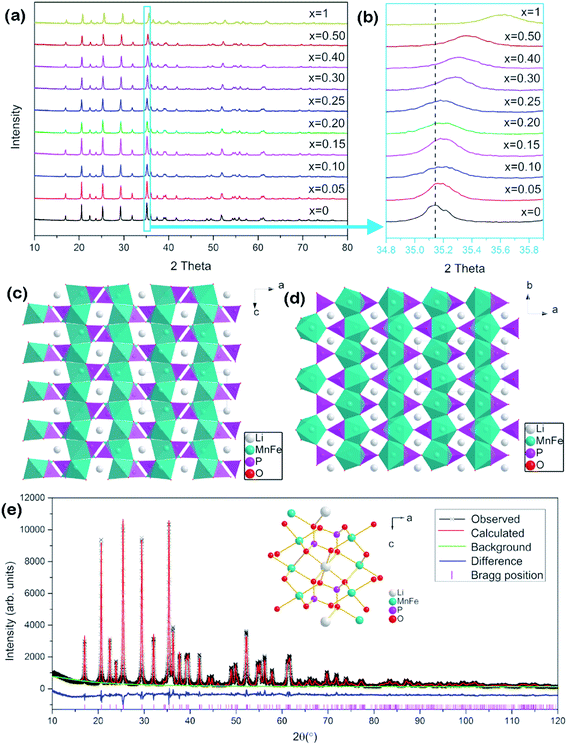
LiMnPO4 and LiFePO4 belong to the olivine crystal structure and possess similar X-ray diffraction (XRD) patterns. Fig. 1a shows the XRD patterns of the series LiMn1−xFexPO4/C materials. As expected, they present similar diffraction peaks at adjacent positions, corresponding to orthorhombic with the space group of Pmnb (as JCPDS No. 74-0375, LiMnPO4). No crystallized carbon phase was found in the patterns, indicating that carbon exists in amorphous state. The carbon contents of ca. 5.3–7.4 wt% were determined by a carbon sulfur analyzer. In detail, it is shown in Table S1.† It is worth noting that the carbon contents of LiMn0.75Fe0.25PO4/C and LiMn0.7Fe0.3PO4/C are 7.35 wt% and 5.86 wt% respectively.As iron proportion increases from 0 to 1, slight peak shift to more 2θ positive values in the diffraction patterns. For example, the peak around 35.14° (2θ) of LiMnPO4 is attributed to crystal plane (111). As x value of LiMn1−xFexPO4 increases, this peak moves toward right up to final position around 35.7°, which is attributed to LiFePO4/C (Fig. 1b). The fine movement of the peaks of XRD patterns proves that the iron gradually occupies the sites which have been occupied by Mn2+ ion. The right shift behavior is associated with the fact that the ion radius of Fe2+ (0.78 Å) is smaller than Mn2+ ion (0.83 Å).24 The basic crystal lattices parameters of a, b, c and V are obviously decreased with the increased iron proportion (Table S1 and Fig. S1†). It gives a strong evidence to prove that the LiMn1−xFexPO4 materials are in a solid solution state.25
The crystal structure of LiMn1−xFexPO4 materials is shown in Fig. 1c and d. Polyanionic framework is constructed by the tetrahedral motifs of PO4 and octahedral groups of LiO6 and MO6. The neighboring MO6 octahedrons share common corners with each other. Neighboring LiO6 octahedrons share the edge forming chains in the b-direction. Each tetrahedral PO4 shares edge with two neighboring octahedral LiO6 and shares corner with two other neighboring LiO6.26–29 The atomic positions, such as LiMn0.7Fe0.3PO4, were calculated by Rietveld structure refinement (Fig. 1e and Table S2†).28,30,31 Fe substituting usually happens in 4c-site which is occupied by Mn ion. However, the cation antisite defects could be arisen, so that a slight amount of Fe/Mn ions (<1%) could occupy 4a site, while Li ions occupy 4c site. So the synthesized route should be strictly controlled to limit the antisite defect.29,31
The chemical compositions of LiMn0.70Fe0.30PO4 and LiMn0.75Fe0.25PO4 were clarified by ICP element analysis, shown in Table 1. The chemical composition of LiMn0.70Fe0.30PO4 from ICP analysis matched the theoretical molar ratio of Li![[thin space (1/6-em)]](https://www.rsc.org/images/entities/char_2009.gif) :
:![[thin space (1/6-em)]](https://www.rsc.org/images/entities/char_2009.gif) Mn
Mn![[thin space (1/6-em)]](https://www.rsc.org/images/entities/char_2009.gif) :
:![[thin space (1/6-em)]](https://www.rsc.org/images/entities/char_2009.gif) Fe
Fe![[thin space (1/6-em)]](https://www.rsc.org/images/entities/char_2009.gif) :
:![[thin space (1/6-em)]](https://www.rsc.org/images/entities/char_2009.gif) P as 1.00
P as 1.00![[thin space (1/6-em)]](https://www.rsc.org/images/entities/char_2009.gif) :
:![[thin space (1/6-em)]](https://www.rsc.org/images/entities/char_2009.gif) 0.70
0.70![[thin space (1/6-em)]](https://www.rsc.org/images/entities/char_2009.gif) :
:![[thin space (1/6-em)]](https://www.rsc.org/images/entities/char_2009.gif) 0.30
0.30![[thin space (1/6-em)]](https://www.rsc.org/images/entities/char_2009.gif) :
:![[thin space (1/6-em)]](https://www.rsc.org/images/entities/char_2009.gif) 1.00(±0.009), similar as LiMn0.75Fe0.25PO4. The elemental concentration ratios are generally close to those of the expected compositions.
1.00(±0.009), similar as LiMn0.75Fe0.25PO4. The elemental concentration ratios are generally close to those of the expected compositions.
| Elemental (%) | Li | Mn | Fe | P | Intended composition | Observed composition |
|---|---|---|---|---|---|---|
| x = 0.25 | 3.78 | 22.78 | 7.494 | 17.02 | LiMn0.75Fe0.25PO4 | Li0.9911Mn0.7544Fe0.2442PO4 |
| x = 0.30 | 4.19 | 23.2 | 10.1 | 18.81 | LiMn0.70Fe0.30PO4 | Li0.9941Mn0.6954Fe0.2979PO4 |
Morphologies
The morphologies of LiMn1−xFexPO4/C series were observed by SEM and TEM testing. SEM images in Fig. 2 reveal the nanoparticle distribution of LiMn1−xFexPO4/C (x = 0–1) materials. LiMn1−xFexPO4/C (x ≠ 0, 1) samples present the particle sizes with a width of ca. 50–80 nm and a length of 60–200 nm, notably smaller than those of LiMnPO4/C and LiFePO4/C. The LiMnPO4/C shows two kind of particle shapes (Fig. 2a), in which the larger particle sizes are ca. 70 nm in width and 100–360 nm in length, and the smaller ones show shorter length of ca. 70 nm. For LiFePO4/C, the primary particles sizes are ca. 50 nm in width and ca. 100 nm in length, and they are assembled to the secondary particles in spindle shape with ca. 100 nm in width and ca. 430 nm in length (Fig. 2j). Iron doping into LiMnPO4 leads to smaller particle size. In particular, when iron proportions are in arrange of 0.20–0.30, the particle size distributions are more even. When iron proportion increases to 0.40, some particles become longer. The element analysis was further analyzed by SEM-EDX. The basic composition of LiMn0.75Mn0.25PO4/C excluding lithium is shown as an example in Fig. S2,† where the molar ratio of Mn![[thin space (1/6-em)]](https://www.rsc.org/images/entities/char_2009.gif) :
:![[thin space (1/6-em)]](https://www.rsc.org/images/entities/char_2009.gif) Fe is 15.04
Fe is 15.04![[thin space (1/6-em)]](https://www.rsc.org/images/entities/char_2009.gif) :
:![[thin space (1/6-em)]](https://www.rsc.org/images/entities/char_2009.gif) 5.02, i.e. nearly 3
5.02, i.e. nearly 3![[thin space (1/6-em)]](https://www.rsc.org/images/entities/char_2009.gif) :
:![[thin space (1/6-em)]](https://www.rsc.org/images/entities/char_2009.gif) 1, matching to the structural formula of the molecule.
1, matching to the structural formula of the molecule.
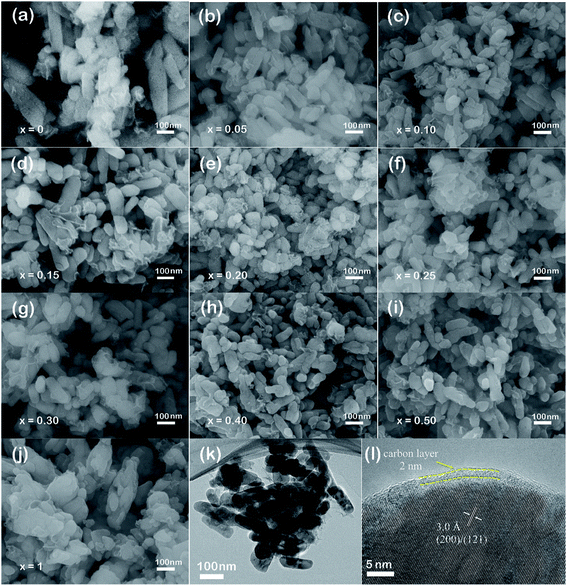 | ||
| Fig. 2 SEM images of LiMn1−xFexPO4/C cathode materials (a–j), TEM and HRTEM images of LiMn0.7Fe0.3PO4/C material (k and l). | ||
The TEM observation further confirms the particle sizes of LiMn0.7Fe0.3PO4/C with the width of ca. 40–50 nm and length of 120–160 nm (Fig. 2k). As shown in the Fig. 2l, the particle surface was uniformly coated by a thin carbon layer with the thickness of ca. 2 nm. Thus the electronic conductivities can be enhanced greatly after carbon coating. Through the high-resolution TEM, the clear crystal lattice with an interplanar spacing of ca. 3.0 Å is displayed, which can be referred to the crystallographic direction of (200) or (121) of LiMn0.7Fe0.3PO4/C.
The LiMn0.7Fe0.3PO4/C material was further examined by XPS analysis shown in Fig. S3.† Two main peaks at 654 eV and 642 eV appealed in the spectrum are attributed to Mn 2p1/2 and Mn 2P3/2, respectively. There is a “shake-up” satellite peak at 646.7 eV belonged to Mn 2P3/2. Peaks at 725 eV and 711 eV are attributed to Fe 2P1/2 and Fe 2P3/2, respectively.
Electrochemical performances
The voltage–capacity profiles of LiMn1−xFexPO4/C materials are compared in Fig. 3. As expected, there is only one discharge voltage plateau of LiMnPO4/C and LiFePO4/C materials at ca. 4.0 V and 3.45 V in the Fig. 3a and f, corresponding to Mn3+/Mn2+ and Fe3+/Fe2+ reductions, respectively. LiMnPO4/C and LiFePO4/C can deliver discharge capacities of 122 mA h g−1 and 152 mA h g−1 at 0.1C, respectively. While Fe is partially substituted in LiMnPO4, the electrochemical performances are clearly improved as shown in the Fig. 3b–e. Two distinct discharge plateaus are ascribed to manganese and iron ions reduction reactions. With the increased iron content, the low voltage plateau becomes longer. LiMn0.7Fe0.3PO4/C shows the highest discharge capacities at different rates, such as 167.6 mA h g−1 at 0.1C, 160.7 mA h g−1 at 0.5C, and 150.6 mA h g−1 at 2C. Its electrochemical performances are superior to most of previous reports on similar Mn rich LiMn1−xFexPO4/C materials (Table 2).11–22,28,32–41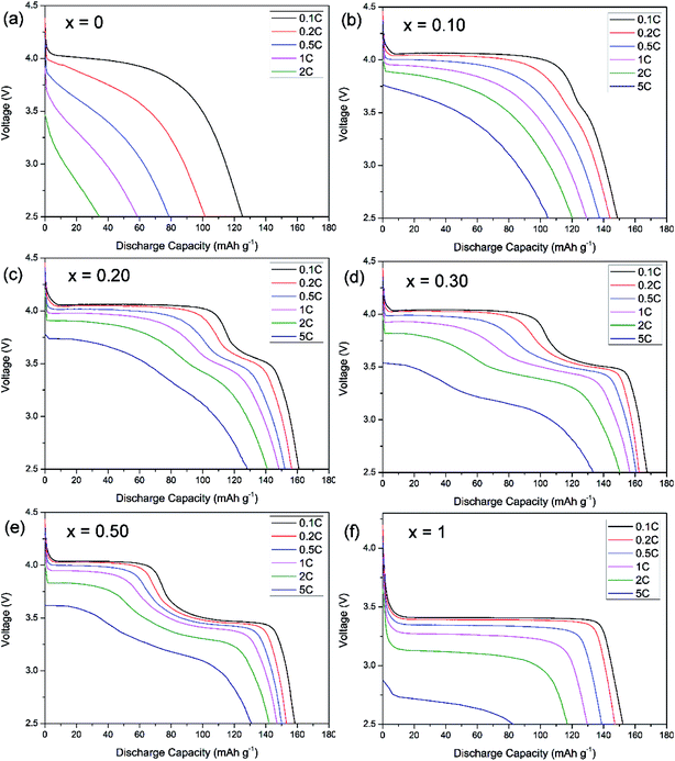 | ||
| Fig. 3 Discharge rate capability of LiMn1−xFexPO4/C with (a) x = 0, (b) x = 0.1, (c) x = 0.20, (d), x = 0.30, (e) x = 0.50, (f) x = 1. | ||
| LiMn1−xFexPO4 electrodes | Cyclic capacity (mA h g−1) | Rate capacity (mA h g−1) | Method | Ref. |
|---|---|---|---|---|
| LiMn0.7Fe0.3PO4 | 167.6@0.1C | 153.9@1C, 139.1@5C | Solvothermal | This work |
| LiMn0.75Fe0.25PO4 | 161.7@0.1C | 141.5@1C, 121.3@5C | Solvothermal | This work |
| LiMn0.7Fe0.3PO4 | ∼150@0.1C | ∼135@1C | Solvothermal | 12 |
| LiMn0.8Fe0.2PO4 | ∼145@0.1C | 130@1C | Solvothermal | 12 |
| LiMn0.7Fe0.3PO4 | ∼120@0.1C | 105@1C | Solid state | 15 |
| LiMn0.6Fe0.4PO4 | 150@0.1C | ∼145@1C, 130@5C | Solid state | 15 |
| LiMn0.75Fe0.25PO4 | 55@0.01C | — | Solvothermal | 16 |
| LiMn0.5Fe0.5PO4 | 153@0.02C | 120@1C | Solvothermal | 16 |
| LiMn0.8Fe0.2PO4 | 111@0.12C | 80@1.2C | Sol–gel | 17 |
| LiMn0.9Fe0.1PO4 | 142@0.12C | 115@1.2C | Sol–gel | 17 |
| LiMn0.8Fe0.2PO4 | 138@0.1C@50 °C | 110@1C@50 °C | Sol–gel | 18 |
| LiMn0.8Fe0.2PO4 | 165.3@0.05C | 142.2@0.5C | Solvothermal | 19 |
| LiMn0.85Fe0.15PO4 | 163.1@0.1C | 150.3@1C, 138@5C | Solvothermal | 20 |
| LiMn0.75Fe0.25PO4 | 157@0.1C | ∼134@1C | Polymer assisted | 21 |
| LiMn0.7Fe0.3PO4 | 130@0.1C | — | Solid state | 22 |
| LiMn0.8Fe0.2PO4 | ∼138@0.1C | — | Sol–gel | 28 |
| LiMn0.8Fe0.2PO4 | 146.5@0.5C | 140@1C, 127@5C | Co-precipitation | 32 |
| LiMn0.8Fe0.2PO4 | 152@0.2C, | 146@1C, 130@5C | Solvothermal | 33 |
| LiMn0.8Fe0.2PO4 | 145@0.2C, | 144@1C, 116@5C | Spray dry | 33 |
| LiMn0.8Fe0.2PO4 | 151@0.1C, | 145@1C, 133@5C | Spray dry, CVD | 34 |
| LiMn0.8Fe0.2PO4 | 161@0.05C | 158@0.5C, ∼124@5C | Polyol synthesis | 35 |
| LiMn0.8Fe0.2PO4 | 162@0.1C, | 145@1C | Solid state | 36 |
| LiMn0.75Fe0.25PO4 | 132@0.1C | 120@1C | Co-precipitation | 37 |
| LiMn0.7Fe0.3PO4 | 160@0.05C | — | Sol–gel | 38 |
| LiMn0.7Fe0.3PO4 | ∼136@0.5C | 107@5C | Solid state | 39 |
| LiMn0.75Fe0.25PO4 | 156@0.1C, | 153@1C, ∼136@5C | Microwave | 40 |
| LiMn0.8Fe0.2PO4 | 142@0.1C | 103@1C, 69@5C | Sol–gel | 41 |
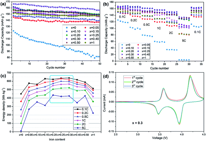
The electrochemical cycle performances of LiMn1−xFexPO4/C at various compositions and current rates are shown in Fig. 4a and b. It can be concluded that partial substitution of iron to manganese in LiMnPO4 can significantly improve the electrochemical performance and LiMn1−xFexPO4/C materials for x value in the range of 0.20–0.30 show better electrochemical performance. Especially, the LiMn0.7Fe0.3PO4/C demonstrates the best performances in the cycle, rate and energy density tests. Its capacity retention at 0.1C reaches 94% for 50 cycles with initial discharge capacity of ca. 167 mA h g−1 which nearly approaches its theoretical value. The electrode exhibits excellent rate capability. In Fig. 4b, it delivers 162.6 and 150.6 mA h g−1 at 0.2C and 2C, respectively. It is notable that higher iron content, such as x = 0.40, or even for LiFePO4, will degrade cycle capacity and rate capability. Here the particle size and carbon coating uniformity may be played an important role in relate electrochemical performances. In view of discharge voltage and the corresponding capacity, LiMn1−xFexPO4/C (x = 0.25–0.30) present a higher energy density (Fig. 4c). The LiMn0.7Fe0.3PO4/C reaches the energy density of 638.3 W h g−1 at 0.1C, 24% higher than that of LiFePO4/C (513.8 W h g−1), which could be considered as a candidate cathode for power lithium-ion batteries.
The cyclic voltammetry result of LiMn0.7Fe0.3PO4/C is investigated as an example at scanning rate of 0.1 mV s−1 in Fig. 4d. Two pairs of peaks are clearly shown at 4.19/3.94, 3.58/3.48 V, which attributed to oxidation and reduction peaks of Mn3+/Mn2+, Fe3+/Fe2+, respectively. The sharper current peaks and symmetry redox peaks indicate the kinetics of Li+ intercalation/deintercalation are greatly ameliorated.
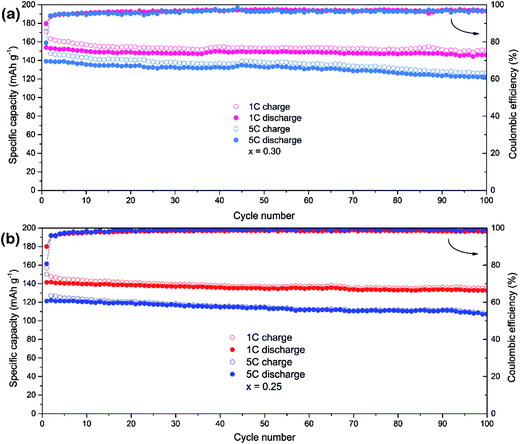
The LiMn0.75Fe0.25PO4/C and LiMn0.7Fe0.3PO4/C materials are selected for a further evaluation of the cycle stability at high rates (Fig. 5). The initial discharge capacities of LiMn0.7Fe0.3PO4/C at rate of 1C and 5C are 153.9 and 139.1 mA h g−1. After 100th cycles at rate of 1C and 5C, LiMn0.7Fe0.3PO4/C still delivers 146 and 122.3 mA h g−1 with the retention of 95% and 88%, respectively. While LiMn0.75Fe0.25PO4/C shows similar cyclability properties, but its capacity is lower as shown in Fig. 5b. The initial discharge capacities at rate of 1C and 5C are 141.5 and 121.3 mA h g−1, respectively.
The electronic conductivities of LiMn0.7Fe0.3PO4/C and LiMn0.75Fe0.25PO4/C were tested by four-probe dc technique which showed the values of ca. 5.8 × 10⁻⁵ S cm−1 and 3.1 × 10⁻⁵ S cm−1 respectively (Table S3†).42,43 The former one owns better conductivity property, benefiting and corresponding with it superior electrochemical performance evidently.
The electrochemical performances of the materials are excellent, even superior to that the aforementioned reports as compared in Table 2. The high capacity, excellent cycle and rate performances can be attributed to short Li+ ions diffusion pathway of the nano-sized particles, thin and even carbon layer coating for enhanced electronic conductivities and iron ions substitution for depressed John–Teller effect.
Conclusion
A series of LiMn1−xFexPO4/C (0 ≤ x ≤ 1) cathode materials for lithium-ion batteries have been successfully synthesized via a facile solvothermal assisted sucrose calcination. LiMn1−xFexPO4 materials belong to olivine solid-solution structure where Fe2+ ions partially substitute Mn2+ ions site in the crystal lattice. The LiMn1−xFexPO4/C (x ≠ 0, 1) samples show nano-sized particle shapes with a width of ca. 50–80 nm, length of 60–200 nm, and thin carbon layer (ca. 2 nm) coating on the surface, while the LiMnPO4/C and LiFePO4/C present slightly larger particles size or aggregated structure. In all the tested materials, LiMn1−xFexPO4/C (x = 0.20–0.30) demonstrate superior electrochemical performances, such as 167.6 mA h g−1 at 0.1C, 153.9 mA h g−1 at 1C and 139.1 mA h g−1 at 5C for LiMn0.7Fe0.3PO4/C. The high capacity and impressive rate performance can be attributed to nanoscale and even particle distribution, uniform thin-layer carbon coating and iron ions substitution. They are promising for practical application in power lithium-ion batteries.Conflicts of interest
There are no conflicts to declare.Acknowledgements
This work was supported by the National Natural Science Foundation of China (51272156, 21373137, 21333007), City Committee of Science and Technology Project of Shanghai (14JC1491800) and New Century Excellent Talents in University (NCET-13-0371).Notes and references
- C. Masquelier and L. Croguennec, Chem. Rev., 2013, 113, 6552–6591 CrossRef CAS PubMed.
- M. S. Whittingham, Chem. Rev., 2014, 114, 11414–11443 CrossRef CAS PubMed.
- N. N. Bramnik and H. Ehrenberg, J. Alloys Compd., 2008, 464, 259–264 CrossRef CAS.
- S. M. Oh, H. G. Jung, C. S. Yoon, S. T. Myung, Z. H. Chen, K. Amine and Y. K. Sun, J. Power Sources, 2011, 196, 6924–6928 CrossRef CAS.
- K. P. Wu, G. R. Hu, Z. D. Peng, Z. J. Zhang, Y. B. Cao and K. Du, RSC Adv., 2015, 5, 95020–95027 RSC.
- G. Li, P. C. Wu, C. H. Luo, Q. Cui, G. X. Wang and K. P. Yan, J. Energy Chem., 2015, 24, 375–380 CrossRef.
- Y. Zhang, H. J. Zhang, Y. Y. Feng, L. Fang and Y. Wang, Small, 2016, 12, 516–523 CrossRef CAS PubMed.
- J. Hong, F. Wang, X. L. Wang and J. Graetz, J. Power Sources, 2011, 196, 3659–3663 CrossRef CAS.
- M. Jo, H. Yoo, Y. S. Jung and J. Cho, J. Power Sources, 2012, 216, 162–168 CrossRef CAS.
- L. G. Wang, P. J. Zuo, G. P. Yin, Y. L. Ma, X. Q. Cheng, C. Y. Du and Y. Z. Gao, J. Mater. Chem. A, 2015, 3, 1569–1579 CAS.
- J. M. Bai, J. Hong, H. Y. Chen, J. Graetz and F. Wang, J. Phys. Chem. C, 2015, 119, 2266–2276 CAS.
- L. J. Hu, B. Qiu, Y. G. Xia, Z. H. Qin, L. F. Qin, X. F. Zhou and Z. P. Liu, J. Power Sources, 2014, 248, 246–252 CrossRef CAS.
- J. Molenda, W. Ojczyk, K. Swierczek, W. Zajac, F. Krok, J. Dygas and R. S. Liu, Solid State Ionics, 2006, 177, 2617–2624 CrossRef CAS.
- M. Yoncheva, V. Koleva, M. Mladenov, M. Sendova-Vassileva, M. Nikolaeva-Dimitrova, R. Stoyanova and E. Zhecheva, J. Mater. Sci., 2011, 46, 7082–7089 CrossRef CAS.
- S. Y. Yan, C. Y. Wang, R. M. Gu, S. Sun and M. W. Li, J. Alloys Compd., 2015, 628, 471–479 CrossRef CAS.
- K. Saravanan, V. Ramar, P. Balaya and J. V. Vittal, J. Mater. Chem., 2011, 21, 14925–14935 RSC.
- S. Novikova, S. Yaroslavtsev, V. Rusakov, A. Chekannikov, T. Kulova, A. Skundin and A. Yaroslavtsev, J. Power Sources, 2015, 300, 444–452 CrossRef CAS.
- L. Damen, F. De Giorgio, S. Monaco, F. Veronesi and M. Mastragostino, J. Power Sources, 2012, 218, 250–253 CrossRef CAS.
- Y. Hong, Z. L. Tang, Z. J. Hong and Z. T. Zhang, J. Power Sources, 2014, 248, 655–659 CrossRef CAS.
- L. H. Liao, H. T. Wang, H. Guo, P. Y. Zhu, J. Xie, C. H. Jin, S. C. Zhang, G. S. Cao, T. J. Zhu and X. B. Zhao, J. Mater. Chem. A, 2015, 3, 19368–19375 CAS.
- P. F. Xiao, B. Ding, M. O. Lai and L. Lu, J. Electrochem. Soc., 2013, 160, A918–A926 CrossRef CAS.
- B. Zhang, X. J. Wang, H. Li and X. J. Huang, J. Power Sources, 2011, 196, 6992–6996 CrossRef CAS.
- B. H. Toby, J. Appl. Crystallogr., 2001, 34, 210–213 CrossRef CAS.
- A. Osnis, M. Kosa, D. Aurbach and D. T. Major, J. Phys. Chem. C, 2013, 117, 17919–17926 CAS.
- A. Iturrondobeitia, A. Goni, I. G. de Muro, L. Lezama, C. J. Kim, M. Doeff, J. Cabana and T. Rojo, Inorg. Chem., 2015, 54, 2671–2678 CrossRef CAS PubMed.
- A. Yamada, Y. Takei, H. Koizumi, N. Sonoyama and R. Kanno, Chem. Mater., 2006, 18, 804–813 CrossRef CAS.
- C. A. J. Fisher, V. M. Hart Prieto and M. Saiful Islam, Chem. Mater., 2008, 20, 5907–5915 CrossRef CAS.
- I. Seo, B. Senthilkumar, K. H. Kim, J. K. Kim, Y. S. Kim and J. H. Ahn, J. Power Sources, 2016, 320, 59–67 CrossRef CAS.
- S. Kandhasamy, K. Nallathamby and M. Minakshi, Prog. Solid State Chem., 2012, 40, 1–5 CrossRef CAS.
- J. Schoiber, G. Tippelt, G. J. Redhammer, C. Yada, O. Dolotko, R. J. F. Berger and N. Hüsing, Cryst. Growth Des., 2015, 15, 4213–4218 CAS.
- K. Jensen, M. Christensen, C. Tyrsted and B. B. Iversen, J. Appl. Crystallogr., 2011, 44, 287–294 CAS.
- W. C. Yang, Y. J. Bi, Y. P. Qin, Y. Liu, X. H. Zhang, B. C. Yang, Q. Wu, D. Y. Wang and S. Q. Shi, J. Power Sources, 2015, 275, 785–791 CrossRef CAS.
- L. T. Yang, Y. G. Xia, L. F. Qin, G. X. Yuan, B. Qiu, J. L. Shi and Z. P. Liu, J. Power Sources, 2016, 304, 293–300 CrossRef CAS.
- L. T. Yang, Y. G. Xia, X. Fan, L. F. Qin, B. Qiu and Z. P. Liu, Electrochim. Acta, 2016, 191, 200–206 CrossRef CAS.
- H. Xu, J. Zong, F. Ding, Z. W. Lu, W. Li and X. J. Liu, RSC Adv., 2016, 6, 27164–27169 RSC.
- H. C. Shim, S. Bang, D. M. Yoon, Y. S. Kong and T. Yu, J. Alloys Compd., 2015, 649, 1315–1322 CrossRef CAS.
- Y. Satou, S. Komine, S. Takai and T. Yao, ECS Electrochem. Lett., 2015, 4, A37–A40 CrossRef CAS.
- S. S. Li, Z. Su, A. Muslim, X. K. Jiang and X. Y. Wang, Ceram. Int., 2015, 41, 11132–11135 CrossRef CAS.
- B. Ding, P. F. Xiao, G. Ji, Y. Ma, L. Lu and J. Y. Lee, ACS Appl. Mater. Interfaces, 2013, 5, 12120–12126 CAS.
- M. S. Kim, J. P. Jegal, K. C. Roh and K. B. Kim, J. Mater. Chem. A, 2014, 2, 10607–10613 CAS.
- B. Z. Li, Y. Wang, L. Xue, X. P. Li and W. S. Li, J. Power Sources, 2013, 232, 12–16 CrossRef CAS.
- Y. Y. Cai, D. Y. Zhang, C. K. Chang, Z. M. Sheng and K. J. Huang, Ionics, 2016, 22, 1011–1019 CrossRef CAS.
- P. R. Kumar, M. Venkateswarlu, M. Misra, A. K. Mohanty and N. Satyanarayana, Ionics, 2013, 19, 461–469 CrossRef CAS.
Footnote |
| † Electronic supplementary information (ESI) available: Refined cell parameters of cathode materials, atomic position of LiMn0.7Fe0.3PO4 determined by Rietveld structure refinement, SEM-EDX spectrum, XPS spectrum, Electronic conductivities. See DOI: 10.1039/c7ra08993g |
| This journal is © The Royal Society of Chemistry 2017 |

