 Open Access Article
Chemical vapor deposition of CuO on ZSM-5 membrane for catalytic wet peroxide oxidation of phenol in a fixed bed reactor
Donglin He ,
Huiping Zhang and
Ying Yan*
School of Chemistry and Chemical Engineering, South China University of Technology, Guangzhou 510640, PR China. E-mail: yingyan@scut.edu.cn; Fax: +86 2087111975; Tel: +86 2087111975
First published on 10th October 2017
Abstract
CuO over ZSM-5 zeolite membrane was prepared by chemical vapor deposition (CVD) for catalytic wet peroxide oxidation (CWPO) of phenol in a fixed bed reactor. Firstly, Cu-ZSM-5/PSSFs catalysts with Cu loading of 2 wt%, 4 wt% and 6 wt% were prepared and characterized by XRD, XPS, SEM, EDS, N2 adsorption–desorption and TPR (H2), respectively. Compared with CuO deposited directly onto PSSFs, the CuO supported on ZSM-5/PSSFs tended to be more regular with smaller crystal size. Then, several parameters affecting H2O2 consumption and phenol oxidation such as reaction temperature, Cu loading, and different supports were investigated in the CWPO of phenol with a high concentration (1 g L−1 phenol and 5.1 g L−1 H2O2). Experimental results revealed that Cu-ZSM-5/PSSFs (6%) showed better activity for the oxidation of phenol than Cu-ZSM-5/PSSFs catalysts with lower Cu loading and CuO/PSSFs with same theoretical loading. A complete reduction of phenol and a high TOC removal around 60% had been achieved over Cu-ZSM-5/PSSFs (6%) at the temperature of 80 °C, feed flow rate of 2 mL min−1 and catalyst bed height of 2 cm. Finally, the possible oxidation pathway of phenol was studied based on the by-products detected by high-performance liquid chromatography (HPLC).
1 Introduction
Phenols are present in the wastewater of various industries, such as refineries, coking operations, coal processing and manufacture of petrochemicals.1 Phenol-containing wastewater can not be discharged into open water without treatment because of the toxicity of phenol. Therefore, the removal of phenol from wastewater is significant to ensure the humans' health and water security. Physical separation,2 biodegradation,3 thermal destruction,4,5 and the advanced oxidation processes (AOPs)6 are the available technologies for the removal of phenol from effluents. Due to the biological and thermal persistence of phenol, the AOPs, primarily based on the action of hydroxyl radicals (˙OH) to oxidize organic pollutants, has been recognized as highly efficient treatment for the wastewater containing phenol, especially if it presents at high concentrations (1–10 g L−1).7 Among them, some processes such as catalytic wet air oxidation (CWAO) or catalytic wet peroxide oxidation (CWPO) are particularly attractive, enabling the abatement of phenol to carbon dioxide and water.8 Unlike the CWAO, in which the operation condition is usually severe (20–200 bar and 200–320 °C),9 the CWPO uses H2O2 as a source of ˙OH and a suitable catalyst for the degradation of the organic species under relatively mild conditions (0.1–0.2 MPa and 20–130 °C).8,10 Moreover, the CWPO also takes an advantage of employing H2O2 as the liquid oxidant to overcome the gas–liquid mass transfer limitations in the process of CWAO.Phenol oxidation has been approached using CWPO with homogeneous catalysts and heterogeneous catalysts under hydrogen.11–13 Hydrogen peroxide is easily decomposed to powerful oxidizing hydroxyl radicals in the present of transition metals (Fe3+, Fe2+, Cu2+) with redox properties.7 However, the use of homogeneous catalysts causes difficulties in the catalyst separation and regeneration. The development of heterogeneous catalysts offers a practical solution to overcome these drawbacks of conventional homogeneous catalysts.
The classical heterogeneous catalysts employed in CWPO consist of an active phase, mainly Fe or Cu, immobilized on the surface of a porous support such as activated carbon,14 silica,15 pillared clays,16 or zeolites,17–21 among others. A interesting overview of strategies for enhanced CWPO of phenol solution is reported by Inchaurrondo et al., in which copper oxides have been found to exhibit a great activity for the catalytic oxidation of organic water pollutants with air or oxygen, but the use of Cu-based catalysts in CWPO process is incipient.22 Zeolite membranes have been confirmed as promising catalytic supports because of their uniform porous structures, unique surface properties, good mechanical strength, good chemical and hydrothermal stabilities, and they can be used directly into a continuous reactor.23–25 It has been reported that ZSM-5 membrane can be supported on PSSFs (paper-like stainless steel fibers)26 and macrocellular b-SiC foams.27 In our previous works, a series of novel ZSM-5/PSSF (paper-like stainless steel fibers with three-dimensional network structure which prepared by wet lay-up papermaking method and sintering process) zeolite membranes used as the catalysts support were synthesized by secondary growth process.23,26,28 Moreover, an obvious enhancement was found in the efficiency of metal modified ZSM-5 zeolite membrane/PSSF catalysts for the CWPO of phenol, confirming a cheerful prospect of these catalysts in the application of CWPO processes.23,25
Recently, chemical vapor deposition (CVD) has been used in the catalysts synthesis, especially for coating the catalytically active metal element onto porous solid support.29 The use of the CVD method has already been demonstrated to present advantages when compared with other methods (such as impregnation, precipitation, and ion exchange) for catalysts preparation. The vital steps such as adsorption, drying, calcination and reduction of conventional heterogeneous catalyst preparation methods may lead to obvious alterations in the catalyst structure and the decrease of the active surface area of catalysts. The CVD process takes advantages of forming high uniform metal or metal oxides thin films onto a particular substrate area without destroying the structure of the support. Another relevant advantage of this technique is that it offers the ability to cover any geometric shape with a deposit of crystalline nanoparticles.30 Those catalysts prepared by the CVD method are usually applied in the gas-phase reaction but seldom utilized in the liquid-phase reaction. Pan et al.31 used a home-made PSE-CVD system to synthesize Cu2O thin films for catalytic oxidation of C2H2 and C3H6. This pure Cu2O catalyst has high efficiency for the complete oxidation of VOCs with good reusability and reproducibility. Zhou et al.28 prepared the Cu/LTA/PSSF catalyst by CVD and tested it in a zeolite membrane reactor. The 10% Cu/LTA/PSSF-CVD in their work presented a high catalytic activity in acetone oxidation (90% of acetone converted at 300 °C). Lam et al.29 used oxygen as a carrier gas in the organic chemical vapor deposition process (MOCVD) to prepare a stable Fe/MCM-41 catalyst. This catalyst showed an excellent mineralization efficiency of orange II of ∼85% in the heterogeneous photo-Fenton's reaction and an extremely low iron leaching concentration of ∼0.17 mg L−1. Although, the catalyst prepared by CVD appears excellent activity in the oxidation of organics has been applied in the CWAO of phenol.32 Few researches are dealing with the CWPO of phenol in a fixed bed with the catalyst prepared by CVD. More importantly, the use of metal modified ZSM-5 zeolite membrane/PSSF catalysts in the fixed bed can enhance conversion, selectivity and catalyst life due to the high contact efficiencies between the catalyst and flow streams.25,33 It also eliminates the need for filtration of catalyst particles, especially important in liquid phase systems.
In this work, we investigated the chemical vapor deposition of CuO on ZSM-5 zeolite membrane to generate a novel catalytic material. The feasibility of this catalyst for the CWPO of phenol wastewater of high concentration (1g L−1) was probed in a fixed bed reactor. Several factors such as reaction temperature, the property of support and the copper loading were examined in the process of the phenol oxidation. Meanwhile, the by-products in the treated water was analyzed to discuses the reaction mechanism of the resulting catalysts.
2 Experimental
2.1 Materials
Stainless steel fibers with diameter about 6.5 μm were purchased from Huitong Advanced Material Company (China). Tetrapropylammonium hydroxide (TPAOH, 25 wt% aqueous) was purchased from Xian Quansheng Fine Chemical Company. Tetraethoxysilane (TEOS, >99%) was gained from Tianjing Fuchen Chemical Reagent Factory. Phenol was purchased from Guangzhou Chemical Reagent Factory. Ethanol (C2H5OH, >99.8%), ammonia water (NH3, 25–28 wt% aqueous) and sodium aluminate (NaAlO2, anhydrous) were all purchased from Sinopharm Chemical reagent Co., Ltd.Phenol was purchased from Guangzhou Chemical Reagent Factory. Hydrogen peroxide (H2O2, 30 wt% aqueous) was obtained from Jiangsu Qiangsheng Chemical Co., Ltd. Manganese dioxide was purchased from Shanghai Qiangshun Chemical Reagent Factory. All of the chemical reagents mentioned above were analytical grade. Copper(II) acetylacetonate or Cu(acac)2 (97%) was purchased from the Aladdin. Deionized water was used in all synthesis process.
2.2 Preparation of Cu-ZSM-5/PSSFs catalyst
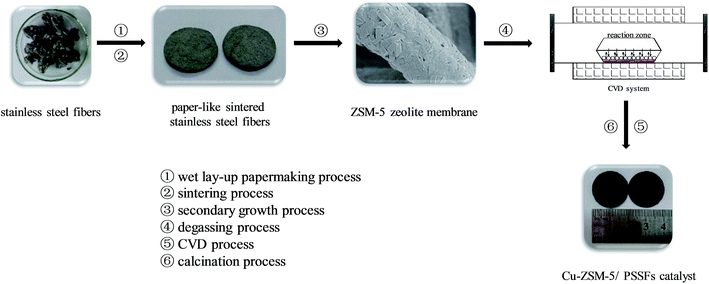
Details of the synthetic procedure of paper-like sintered stainless steel fibers (PSSFs) and ZSM-5 membrane/PSSFs were reported in our previous paper.34 The schematic diagram of Cu-ZSM-5/PSSFs catalysts synthetic strategy is shown in Fig. 1. In this study, the ZSM-5 membrane support with a Si/Al ratio of 80 was synthesized by the secondary growth method. Cu active component was deposited on the ZSM-5 membrane by means of CVD. ZSM-5/PSSFs, Cu-ZSM-5/PSSFs (a%) and CuO/PSSFs catalysts were prepared in this work. The a% mentioned above are the theoretical mass ratio of Cu in the catalyst. Copper(II) acetylacetonate or Cu(acac)2 was used as the precursor material without further purification for the deposition of copper on ZSM-5 membrane or PSSFs. Target substrate was dried at 100 °C for 12 h before the deposition experiment. Firstly, the mixtures of precursor and support was degassed thrice under vacuum condition at room temperature with nitrogen exchange to create a high purity nitrogen atmosphere in the CVD reactor. Then the reactor treated at a evaporation temperature of 180 °C for 30 min. After the solid precursor sublimes and forms Cu(acac)2 vapor in the reactor, the deposition temperature of 350 °C was attained quickly and kept for 120 min to let precursor vapor decompose fully so that the active metal element Cu was deposited onto the support. The deposition experiment was carry out under an atmospheric pressure with nitrogen atmosphere. Moreover, the pressure of the CVD reactor was kept around 0.10–0.12 Mpa. At last, in order to oxidize the deposited Cu into CuO, the samples were calcined in air with a heating rate of 1 °C min−1 until 550 °C in a muffle furnace for 6 h.2.3 Characterization of Cu-ZSM-5/PSSFs catalyst
The crystallinity and structure of Cu-ZSM-5/PSSFs catalyst and copper status on ZSM-5 membrane were studied by X-ray diffraction (XRD) techniques on a PANalytical X′ Pert Pro X-ray diffractometer using Cu Kα radiation (40 kV, 40 mA) with 2θ range from 5° to 60°. X-ray photo-electron spectroscopy (XPS) spectra were recorded on a Kratos Axis Ultra (DLD) instrument and using an aluminium Kα radiation source operated at 15 kV and 10 mA. The binding energy (B.E.) of C 1s peak at 284.6 eV was taken as a reference. The textural and morphological information of the samples were characterized using field emission scanning electronic microscopy (FE-SEM) on a Zeiss Merlin FE-SEM. Before analysis, all of the samples were coated with an ultrathin film of platinum to make them conductive. The energy dispersive spectroscopy (EDS) and element mapping were applied to analyze the dispersion of Fe in the catalyst samples. N2 adsorption–desorption isotherms at 77 K were measured on an ASAP 2020 (Micromeritics Instrument Co., USA). H2-Temperature programmed reduction (TPR) tests were conducted on Quantachrome Automated Chemisorption Analyzer by heating the catalyst in H2 (10 vol%)/Ar flow (30 mL min−1) at a heating rate of 10 °C min−1 from room temperature to 700 °C. The hydrogen consumption was detected by thermo-conductivity detector (TCD).2.4 Catalyst wet peroxide oxidation of phenol over Cu-ZSM-5/PSSFs catalyst
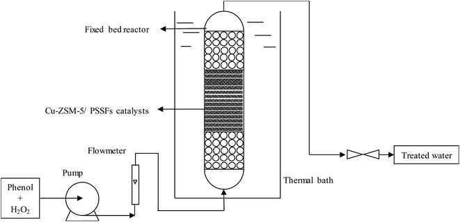
CWPO of phenol was performed in a fixed bed reactor made of a stainless steel tube (20 mm i.d., 100 mm length) under atmospheric pressure. As shown in Fig. 2, the catalysts were fixed in the reactor between two layers of spherical inert glass particles (d = 2–3 mm) to improve the distribution of the inlet fluid. The aqueous solution in the feed tank including 1 g L−1 of phenol and 5.1 g L−1 of H2O2 was fed to the up-flow mode reactor by a peristaltic pump (stoichiometric amount for the total phenol oxidation according to reaction 1). The temperature in the fixed bed reactor was controlled by water bath heat.| C6H5OH + 14H2O2 → 6CO2 + 17H2O | (1) |
H2O2 and TOC conversions were measured by the method mentioned in our previous paper.19 The phenol and other organics in treated fluid were analyzed by HPLC (Agilent 1100) equipped with a UV detector adjusted at 210 nm and an Agilent HC-C18(2) column (5 μm × 250 mm × 4.6 mm) of which the mobile phase is 1 mL min−1 of methanol solution (MeOH![[thin space (1/6-em)]](https://www.rsc.org/images/entities/char_2009.gif) :
:![[thin space (1/6-em)]](https://www.rsc.org/images/entities/char_2009.gif) H2O = 30
H2O = 30![[thin space (1/6-em)]](https://www.rsc.org/images/entities/char_2009.gif) :
:![[thin space (1/6-em)]](https://www.rsc.org/images/entities/char_2009.gif) 70 vol%).
70 vol%).
3 Results and discussion
3.1 Characterization
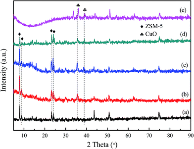 | ||
| Fig. 3 XRD patterns of the samples: (a) ZSM-5/PSSFs, (b) Cu-ZSM-5/PSSFs (2%), (c) Cu-ZSM-5/PSSFs (4%), (d) Cu-ZSM-5/PSSFs (6%) and (e) CuO/PSSFs. | ||
For all the Cu loaded catalysts, the diffraction peaks attributed to crystalline CuO phase were detected at 2θ = 35.5° and 2θ = 38.7° which are assigned to (![[1 with combining macron]](https://www.rsc.org/images/entities/char_0031_0304.gif) 11) and (111) reflections of the CuO crystals (JCPDS no. 80-1268), respectively.36,37 The two clear CuO diffraction peaks in Cu-ZSM-5/PSSFs catalysts and the Cu-ZSM-5/PSSFs catalysts suggests that the copper loaded by CVD on the ZSM-5 membrane and the PSSF support both existed as CuO crystallites.
11) and (111) reflections of the CuO crystals (JCPDS no. 80-1268), respectively.36,37 The two clear CuO diffraction peaks in Cu-ZSM-5/PSSFs catalysts and the Cu-ZSM-5/PSSFs catalysts suggests that the copper loaded by CVD on the ZSM-5 membrane and the PSSF support both existed as CuO crystallites.
For Cu-ZSM-5/PSSFs catalysts, the intensities of the ZSM-5 diffraction peaks decreased slightly with increasing theoretical Cu loading from 2 wt% to 6 wt%. This result can be explained by the CuO formation in the pores or the formation of CuO on the ZSM-5 membrane surface.
The average crystal sizes of CuO, calculated from the Scherrer equation after Warren's correction for instrument are shown in Table 2. The CuO crystal size of Cu-ZSM-5/PSSFs (6%) was about 14.08 nm, which was smaller compared with that of the CuO/PSSFs (about 17.21 nm). Due to the similar theoretical Cu loading for these two catalysts, this result indicates that the crystal size of CuO deposited on the support by CVD process can be affected by the surface property of the support.
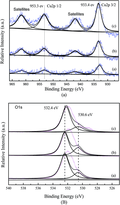
The XPS results of O 1s of Cu-ZSM-5/PSSFs catalysts were displayed in Fig. 4(b), asymmetric two-band structures were observed for all the catalyst samples. The O 1s peak at 532.4 eV observed on all the samples could be assigned to surface adsorbed oxygen.41 The O 1s peak at 530.6 eV observed on the Cu-ZSM-5/PSSFs catalysts was assigned to oxygen in CuO.42–44 In conclusion, the XPS results match well with XRD characterization that CuO was formed onto the support.
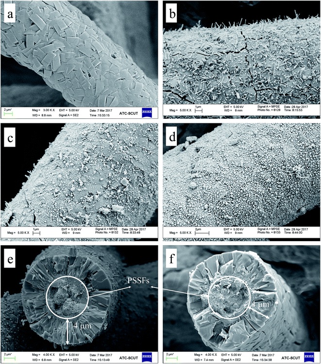
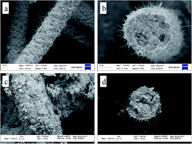
Microstructure of the Cu-ZSM-5/PSSFs (2%), Cu-ZSM-5/PSSFs (4%) and Cu-ZSM-5/PSSFs (6%) are shown in Fig. 5(b–d), the surface morphological of CuO with randomly oriented sub-micro sized grains varied widely according to the ratio of copper. The CuO grains formed on the ZSM-5 membrane ranged in shape from the needle-shape for a low copper loading (2 wt%) to the spherical-shape for a high copper loading. When the loading of copper increased to 6 wt%, the dense and uniform CuO film formed on the ZSM-5 membrane, which could be the main reason for the decrease of the intensities of ZSM-5 diffraction peaks detected by XRD.
The surface morphological images of CuO supported directly on PSSFs with the theoretical Cu loading of 6 wt% are shown in Fig. 6(c and d). Fig. 6(c) exposes the irregularly arranged sub-microsized flake – like structure of CuO on the PSSFs support. Compared with the CuO film of the CuO/PSSFs, the CuO deposited on ZSM-5 membrane tended to be more regular.
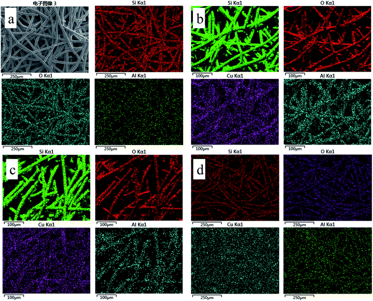 | ||
| Fig. 7 EDS elemental mapping images of the sample: (a) ZSM-5 zeolite membrane support, (b) Cu-ZSM-5/PSSFs (2%), (c) Cu-ZSM-5/PSSFs (4%), (d) Cu-ZSM-5/PSSFs (6%). | ||
| Elements (wt%) | Samples | ||||
|---|---|---|---|---|---|
| ZSM-5/PSSFs | Cu-ZSM-5/PSSFs (2%) | Cu-ZSM-5/PSSFs (4%) | Cu-ZSM-5/PSSFs (6%) | CuO/PSSFs | |
| Si | 50.05 | 47.38 | 43.24 | 42.30 | — |
| O | 49.60 | 46.96 | 46.11 | 42.91 | 13.29 |
| Al | 0.35 | 0.33 | 0.41 | 0.36 | — |
| Cu | — | 5.31 | 10.24 | 14.43 | 17.57 |
| Fe | — | — | — | — | 55.31 |
| Cr | — | — | — | — | 11.23 |
| Mn | — | — | — | — | 0.68 |
| Ni | — | — | — | — | 1.92 |
For the Cu-ZSM-5/PSSFs catalysts, the ratio of Cu loaded on catalysts detected by EDS increased with the increase of the theoretical Cu loading, which was much higher than the theoretical Cu load. Because the elemental composition examined by EDS is the value on the surface of samples with a limited thickness.45 The ZSM-5 membrane with the thickness of 4 μm can cover the PSSF completely, and CuO formed by CVD is too thin to prevent the detection of elements of Si, Al. As shown in Fig. 7(b–d), the filiform distribution of Cu element confirms the well dispersion of the active component on the surface of the support.
Overall, these results indicate that the Cu content of Cu-ZSM-5/PSSFs catalysts existed alongside the ZSM-5 membrane surface with a well distribution.
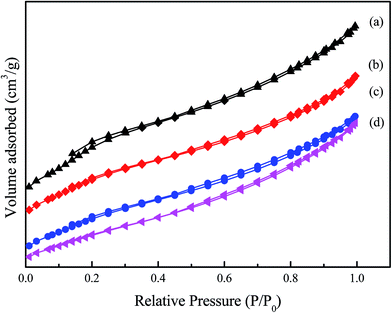 | ||
| Fig. 8 N2 adsorption–desorption isotherms of the samples at 77 K: (a) ZSM-5 zeolite membrane support, (b) Cu-ZSM-5/PSSFs (6%), (c) Cu-ZSM-5/PSSFs (2%), (d) Cu-ZSM-5/PSSFs (4%). | ||
| Materials | Average crystallite size of CuO (nm) | SBET (m2 g−1) | Vtotal (cm3 g−1) | Vmicro (cm3 g−1) | Cu content of surface (EDS) (wt%) | Cu content (theoretical value) (wt%) |
|---|---|---|---|---|---|---|
| a Average crystallite size of CuO investigated by XRD and calculated by the Scherrer equation; SBET: surface area calculated by the BET (Brunauer–Emmett–Teller) method; Vmicro: micropore volume calculated from t-plot. | ||||||
| PSSF | 0 | 0.36 | 0.0293 | — | 0 | 0 |
| ZSM-5/PSSFs | 0 | 189.32 | 0.1287 | 0.0437 | 0 | 0 |
| Cu-ZSM-5/PSSFs (2%) | 16.08 | 135.37 | 0.0978 | 0.0351 | 5.31 | 2 |
| Cu-ZSM-5/PSSFs (4%) | 18.08 | 122.47 | 0.0953 | 0.0344 | 10.24 | 4 |
| Cu-ZSM-5/PSSFs (6%) | 14.08 | 163.49 | 0.0112 | 0.0453 | 14.43 | 6 |
| CuO/PSSFs | 17.21 | 0.04 | 0.0285 | — | 17.57 | 6 |
It can be observed that ZSM-5/PSSFs and Cu-ZSM-5/PSSFs catalysts present isotherms type II with H3-type hysteresis loop at a high relative pressure. The shape of the loop seems to be unaltered after the CuO formation, indicating that the CVD process do not result in pore structure collapse. As shown in Fig. 8, the volume adsorbed for all isotherms increases with the increasing relative pressure, which can be caused by the multilayer adsorption and confirm the existence of micropores in ZSM-5/PSSFs and Cu-ZSM-5/PSSFs catalysts.
Then, the main shifts concern the values of textural properties. Indeed, the curves are found to shift down along the y-axis with the increase in copper loading. The surface area decreased with the increase of Cu loading, although the SBET of Cu-ZSM-5/PSSFs (6%) was little lager than the value of catalysts with Cu loading of 2 wt% and 4 wt%. Meanwhile, the pore volume and the micropore volume had a similar shift. These evolutions can be explained by the filling of the pores by the CuO phase.46 Some CuO particles at size lower than the pores size of the ZSM-5 membrane support was formed into the pores of the support. As shown in Table 2 and Fig. 8, XRD analysis and SEM micrographs confirm the formation of the dense and uniform CuO film when the loading of copper increased to 6 wt%, and the average crystal size of CuO loaded on Cu-ZSM-5/PSSFs (6%) was smaller compared with the value of Cu-ZSM-5/PSSFs (2%) and Cu-ZSM-5/PSSFs (4%). Therefore, the surface area and pore volume of Cu-ZSM-5/PSSFs (6%) had a slighter decrease than the properties of Cu-ZSM-5/PSSFs with copper ratios of 2 wt% and 4 wt%.
The surface area and pore volume of the catalyst play a key role during the catalytic reaction, especially in liquid phase.18 Indeed, if the surface area of the catalyst is not enough, the contact of the pollutant and the active site will be minimized. The pore volume and pore size also affect the diffusion of the molecules in the pore, up to the active. Compared with that the CuO/PSSFs that has a small internal surface area, the Cu-ZSM-5/PSSFs with a porous structure and a large internal surface area would favor the contact of the pollutant and the active site and lead to higher reaction rates.
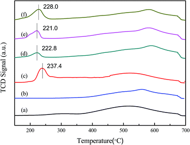
With the Cu loading of Cu-ZSM-5/PSSFs increasing, the intensities of the reduction peaks increase, and the Tmax of the peaks have a slight shift. The reduction profile of CuO/PSSFs catalyst shows a narrow peak with Tmax at 237.4 °C, the value of which is higher than the Tmax of Cu-ZSM-5/PSSFs at 221–228 °C. Because the reduction of highly dispersed CuO is easier than the reduction of the bulk CuO that is expected to get reduced at higher temperature.49 The results above indicates that the CuO deposited on ZSM-5 membrane is more highly distributed than the CuO loaded on PSSFs, and confirms that the distribution and size of CuO grains formed by CVD process are mainly affected by the property of the support.
| CuO + H2 → Cu + H2O | (2) |
3.2 Phenol oxidation over Cu-ZSM-5/PSSFs catalysts in a fixed bed reactor
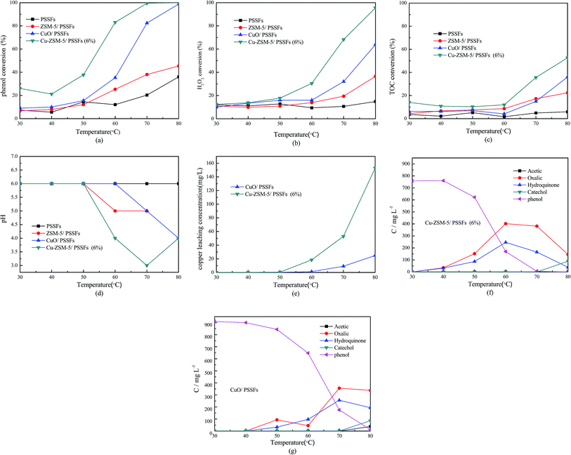
As shown in Fig. 10, the PSSFs had no obvious activity for the CWPO of phenol with a low phenol conversion and a low TOC removal at all temperatures. The low H2O2 consumption (about 10%) of PSSFs at high reaction temperature indicates that the thermal decomposition of H2O2 under 80 °C was limited.
Fig. 10 also shows that enhancements of ZSM-5/PSSFs, Cu-ZSM-5/PSSFs (6%) and CuO/PSSFs in the mineralization of phenol were observed with the temperature increasing. The conversion of the phenol, H2O2 and TOC increased dramatically with the reaction temperature increasing from 60 °C to 80 °C. At 70 °C, the phenol conversion of the Cu-ZSM-5/PSSFs (6%) was up to almost 100% with TOC removal of 35.6%. In contrast, a high TOC conversion (almost 60%) and a complete conversion of phenol achieved with the Cu-ZSM-5/PSSFs at 80 °C. This because more ˙OH radicals forming at higher reaction temperature increase the degradation rate of phenol in the CWPO reaction.16 Therefore, it is necessary to increase the temperature to achieve higher degrees of mineralization.
The presence of ZSM-5/PSSFs without any Cu loading resulted in very limited phenol conversion and TOC removal. This result indicates that the efficiency of ZSM-5 membrane was negligible and CuO deposited on ZSM-5 zeolite membrane were quite active for oxidation of phenol.
As can be seen in Fig. 10(a–c), the activity of Cu-ZSM-5/PSSFs (6%) for the oxidation of phenol was much higher than the efficiency of CuO/PSSFs at all operation temperature. Moreover, the evolution of intermediates and/or by-products for the CWPO of phenol with these two catalysts was monitored with the temperature increasing from 30 °C to 80 °C, which is shown in Fig. 10(f and g) respectively. The acetic acid, oxalic acid, hydroquinone and catechol were detected in the outlet fluid treated by the two catalysts. As shown in Fig. 10(f), with the Cu-ZSM-5/PSSFs (6%) catalyst, the concentrations of the oxalic acid and hydroquinone increased as the temperature climbed from 30 °C to 60 °C. When the temperature raised from 70 °C to 80 °C, the amounts of by-products especially the oxalic acid decreased dramatically. Meanwhile, the increase of pH value shown in Fig. 10(d) is observed with the decrease of the concentration of oxalic acid, indicating that the accumulation of the acid leaded to the low pH value of the outlet flow. But the concentration of Cu leaching increased with the increase of temperature from 50 °C to 80 °C, not according to the concentration of oxalic acid in the treated flow. This because the leaching of Cu mainly results from the contact of the active content of catalysts with acids produced in the process of the oxidation of phenol. The high reaction temperature can contribute to high total amounts of acids in the stage that the aromatic intermediates are converted into low-molecular-weight organic acids. The acids forming in this stage resulted in the Cu leaching and then would be removed quickly by the further oxidation in the fixed bed, however the complete removal of the oxalic acid was difficult under 80 °C.
In contrast, the CuO/PSSFs sees a slight shift in the concentration of by-products with the temperature increasing from 70 °C to 80 °C. The amount of Cu leaching also was lower compared the value of Cu-ZSM-5/PSSFs (6%) because of the lower concentration of the acid intermediates produced by the conversion of phenol and aromatic intermediates with CuO/PSSFs. Overall, these results match well with the characterization results that the ZSM-5 membrane with the uniform pore structure is the better support than the PSSFs for the copper content loading.
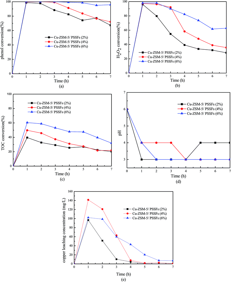
As shown in Fig. 11(b), the consumption of H2O2 of all the Cu-ZSM-5/PSSFs catalysts decreased obviously with time. A similar trend can be seen in the TOC conversion. Meanwhile, the gap between the conversions of TOC and H2O2 narrowed with the time. This phenomenon attributed to the decline of the Cu leaching concentration with time. It has been reported that continuous leaching would result gradually in heterogeneous catalyst deactivation and dissolved metal ions would result in a homogeneous/heterogeneous coupled reaction system rather than an absolute heterogeneous reaction system.37 At beginning of the run, the conversion of H2O2 is much higher than the TOC conversion. Due to the formation of a larger amount of low-molecular-weight organic acid in the oxidation process, the concentration of Cu leaching was much higher during initial 3 hours. The existence of Cu2+ can promote the conversion of H2O2 at high temperatures and in a wide-working pH range (pH 3–7).13 Due the continues removal of Cu2+ in the fixed bed reactor, the homogeneous reaction is limited in this system. Fig. 10 showed that the TOC removal of 45% was achieved with Cu-ZSM-5/PSSFs (6%) when the Cu leaching was down to 7 ppm. With the amount of Cu leaching rising nearly 20 times, the TOC conversion only had a slight increase. That means the homogeneous reaction of Cu2+ in our designed CWPO system was negligible.
![[thin space (1/6-em)]](https://www.rsc.org/images/entities/char_2009.gif) :
:![[thin space (1/6-em)]](https://www.rsc.org/images/entities/char_2009.gif) H2O = 30
H2O = 30![[thin space (1/6-em)]](https://www.rsc.org/images/entities/char_2009.gif) :
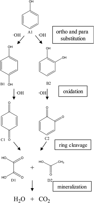
:![[thin space (1/6-em)]](https://www.rsc.org/images/entities/char_2009.gif) 70 vol%). HPLC analysis of the treated water from the CWPO process showed the formation of several intermediate products. As reported in Table 3, acetic acid, oxalic acid, hydroquinone and catechol were the identified by-products in the outlet fluid. Based on the identified products and previous studies of the degradation of phenol,50–52 a possible phenol degradation pathway is displayed in Fig. 12. As the ˙OH radicals are generated by the interaction between the hydrogen peroxide molecule and the CuO active site, the phenol is attacked by ˙OH radicals and firstly converted to hydroquinone (B1) and catechol (B2) through para and ortho substitutions. Due to nonelection of ˙OH radicals,53 they can directly oxidize intermediates B1, B2 to p-benzoquinone (C1) and 1,2-benzoquinone (C2). Then C1, C2 underwent ring broken down to generate some short-chain organic acids including oxalic acid (D1) and acetic acid (D2). Finally, the mineralization of these organic chains during reaction leads to CO2 and H2O formation. Some of the intermediates, mainly the short-chain organic acids such as oxalic acid, are however refractory to the oxidation. This can explain why residual TOC remains after almost complete removal of phenol. Moreover, one of the most interesting options was to use CWPO as a pre-treatment prior to biological treatment, for simple organic acid that are highly biodegradable.54 For this reason, the results obtained in the present work, with phenol degradation beyond 95% and TOC removal beyond 50% suggests that further work with CuO supported on ZSM-5 zeolite membrane as catalysts for pre-treatments like CWPO of phenol would be extremely valuable. On the other hand, the generation of these acids has been reported to the main reason for this limited stability copper-based systems.55 Therefore, we will also focus on how to separate out these acids from the catalytic system during the CWPO process in order to reduce the leaching of Cu.
70 vol%). HPLC analysis of the treated water from the CWPO process showed the formation of several intermediate products. As reported in Table 3, acetic acid, oxalic acid, hydroquinone and catechol were the identified by-products in the outlet fluid. Based on the identified products and previous studies of the degradation of phenol,50–52 a possible phenol degradation pathway is displayed in Fig. 12. As the ˙OH radicals are generated by the interaction between the hydrogen peroxide molecule and the CuO active site, the phenol is attacked by ˙OH radicals and firstly converted to hydroquinone (B1) and catechol (B2) through para and ortho substitutions. Due to nonelection of ˙OH radicals,53 they can directly oxidize intermediates B1, B2 to p-benzoquinone (C1) and 1,2-benzoquinone (C2). Then C1, C2 underwent ring broken down to generate some short-chain organic acids including oxalic acid (D1) and acetic acid (D2). Finally, the mineralization of these organic chains during reaction leads to CO2 and H2O formation. Some of the intermediates, mainly the short-chain organic acids such as oxalic acid, are however refractory to the oxidation. This can explain why residual TOC remains after almost complete removal of phenol. Moreover, one of the most interesting options was to use CWPO as a pre-treatment prior to biological treatment, for simple organic acid that are highly biodegradable.54 For this reason, the results obtained in the present work, with phenol degradation beyond 95% and TOC removal beyond 50% suggests that further work with CuO supported on ZSM-5 zeolite membrane as catalysts for pre-treatments like CWPO of phenol would be extremely valuable. On the other hand, the generation of these acids has been reported to the main reason for this limited stability copper-based systems.55 Therefore, we will also focus on how to separate out these acids from the catalytic system during the CWPO process in order to reduce the leaching of Cu.
4 Conclusions
The CuO deposited on ZSM-5 zeolite membrane by CVD is a promising catalyst for the CWPO of phenolic wastewaters in an up-flow fixed bed reactor. The CuO grains formed on the ZSM-5 membrane ranged in shape from the needle-shape for a low copper loading (2 wt%) to the spherical-shape for a high copper loading. When the loading of copper increased to 6 wt%, the dense and uniform CuO film can be formed on the ZSM-5 membrane without pore structure collapse. Compared with the CuO deposited directly onto PSSFs, the CuO supported on ZSM-5/PSSFs tended to be more regular with smaller crystal size and show higher efficiency for the CWPO of phenol. The efficiency of the catalyst was improved by the increase of copper loading (from 2 wt% to 6 wt%). A complete reduction of phenol and a high TOC removal around 60% had been achieved over the Cu-ZSM-5/PSSFs (6%) at the temperature of 80 °C, feed flow rate of 2 mL min−1 and catalyst bed height of 2 cm. In the CWPO of phenol (1000 ppm phenol and 5.1 g L−1 H2O2) over Cu-ZSM-5/PSSFs (6%), hydroquinone and catechol were produced first and then lower organic acid (mainly acetic acid and oxalic acid) accumulated and were ultimately mineralized to CO2 and H2O.Conflicts of interest
There are no conflicts to declare.Acknowledgements
The authors gratefully acknowledge the financial support from the National Natural Science Foundation of China (Grant No. 21776106), and Pearl River S&T Nova Program of Guangzhou (Grant No. 201610010171) for this work.References
- N. S. Inchaurrondo, P. Massa, R. Fenoglio, J. Font and P. Haure, Chem. Eng. J., 2012, 198–199, 426–434 CrossRef CAS.
- W. Kujawski, A. Warszawski, W. Ratajczak, T. Porebski, W. Capala and I. Ostrowska, Desalination, 2004, 163, 287–296 CrossRef CAS.
- H.-L. Jiang, J.-H. Tay, A. M. Maszenan and S. T.-L. Tay, Environ. Sci. Technol., 2006, 40, 6137–6142 CrossRef CAS PubMed.
- T. V. Chubar, F. D. Ovcharenko, V. N. Vysotskaya and Z. G. Bovkun, Kolloidn. Zh., 1979, 41, 196–199 CAS.
- A. A. Khaibullin, R. N. Galiakhmetov and A. A. Mukhamedzyanova, Bashk. Khim. Zh., 2002, 9, 3–15 CAS.
- O. Gimeno, M. Carbajo, F. J. Beltran and F. J. Rivas, J. Hazard. Mater., 2005, 119, 99–108 CrossRef CAS PubMed.
- G. Busca, S. Berardinelli, C. Resini and L. Arrighi, J. Hazard. Mater., 2008, 160, 265–288 CrossRef CAS PubMed.
- A. Quintanilla, A. F. Fraile, J. A. Casas and J. J. Rodriguez, J. Hazard. Mater., 2007, 146, 582–588 CrossRef CAS PubMed.
- J. A. Zazo, J. A. Casas, A. F. Mohedano and J. J. Rodriguez, Appl. Catal., B, 2006, 65, 261–268 CrossRef CAS.
- K. Huang, J. Wang, D. Wu and S. Lin, RSC Adv., 2015, 5, 8455–8462 RSC.
- N. Platon, I. Siminiceanu, I. D. Nistor, N. D. Miron, G. Muntianu and A. M. Mares, Rev. Chim., 2011, 62, 676–679 CAS.
- J. Restivo, O. S. G. P. Soares, J. J. M. Orfao and M. F. R. Pereira, Chem. Eng. J., 2017, 309, 197–205 CrossRef CAS.
- N. Inchaurrondo, E. Contreras and P. Haure, Chem. Eng. J., 2014, 251, 146–157 CrossRef CAS.
- A. Rey, M. Faraldos, J. A. Casas, J. A. Zazo, A. Bahamonde and J. J. Rodriguez, Appl. Catal., B, 2009, 86, 69–77 CrossRef CAS.
- L. Xiang, S. Royer, H. Zhang, J. M. Tatibouët, J. Barrault and S. Valange, J. Hazard. Mater., 2009, 172, 1175–1184 CrossRef CAS PubMed.
- J. Barrault, C. Bouchoule, K. Echachoui, N. Frini-Srasra, M. Trabelsi and F. Bergaya, Appl. Catal., B, 1998, 15, 269–274 CrossRef CAS.
- Y. Yan, X. Wu and H. Zhang, Sep. Purif. Technol., 2016, 171, 52–61 CrossRef CAS.
- X. Zhong, J. Barbier Jr, D. Duprez, H. Zhang and S. Royer, Appl. Catal., B, 2012, 121–122, 123–134 CrossRef CAS.
- Y. Yan, S. Jiang and H. Zhang, Sep. Purif. Technol., 2014, 133, 365–374 CrossRef CAS.
- S. Garg, V. C. Srivastava, S. Singh and T. K. Mandal, Int. J. Chem. React. Eng., 2015, 13, 437–445 CAS.
- F. Martinez, J. A. Melero, J. A. Botas, M. I. Pariente and R. Molina, Ind. Eng. Chem. Res., 2007, 46, 4396–4405 CrossRef CAS.
- N. Inchaurrondo, J. Cechini, J. Font and P. Haure, Appl. Catal., B, 2012, 111–112, 641–648 CrossRef CAS.
- S. Jiang, H. Zhang and Y. Yan, Catal. Commun., 2015, 71, 28–31 CrossRef CAS.
- S. Jiang, H. Zhang, Y. Yan and X. Zhang, RSC Adv., 2015, 5, 41269–41277 RSC.
- Y. Yan, S. Jiang, H. Zhang and X. Zhang, Chem. Eng. J., 2015, 259, 243–251 CrossRef CAS.
- Y. Yan, L. Wang and H. Zhang, Chem. Eng. J., 2014, 255, 195–204 CrossRef CAS.
- X. Ou, S. Xu, J. M. Warnett, S. M. Holmes, A. Zaheer, A. A. Garforth, M. A. Williams, Y. Jiao and X. Fan, Chem. Eng. J., 2017, 312, 1–9 CrossRef CAS.
- C. Zhou, H. Zhang, Y. Yan and X. Zhang, Microporous Mesoporous Mater., 2017, 248, 139–148 CrossRef CAS.
- F. L. Y. Lam and X. Hu, Catal. Commun., 2007, 8, 1719–1723 CrossRef CAS.
- J. Ramírez-Ortiz, T. Ogura, J. Medina-Valtierra, S. a. E. Acosta-Ortiz, P. Bosch, J. Antonio de los Reyes and V. H. Lara, Appl. Surf. Sci., 2001, 174, 177–184 CrossRef.
- G.-F. Pan, S.-B. Fan, J. Liang, Y.-X. Liu and Z.-Y. Tian, RSC Adv., 2015, 5, 42477–42481 RSC.
- H. P. Chu, L. Lei, X. Hu and P.-L. Yue, Energy Fuels, 1998, 12, 1108–1113 CrossRef CAS.
- O. P. Taran, A. N. Zagoruiko, A. B. Ayusheev, S. A. Yashnik, R. V. Prihod’ko, Z. R. Ismagilov, V. V. Goncharuk and V. N. Parmon, Chem. Eng. J., 2015, 282, 108–115 CrossRef CAS.
- H. H. Chen, H. P. Zhang and Y. Yan, Chem. Eng. J., 2012, 209, 372–378 CrossRef CAS.
- C. Falamaki, M. Edrissi and M. Sohrabi, Zeolites, 1997, 19, 2–5 CrossRef CAS.
- K. W. Yao, S. Jaenicke, J. Y. Lin and K. L. Tan, Appl. Catal., B, 1998, 16, 291–301 CrossRef CAS.
- G. Zhang, S. Wang, S. Zhao, L. Fu, G. Chen and F. Yang, Appl. Catal., B, 2011, 106, 370–378 CrossRef CAS.
- M. G. Mendez-Medrano, E. Kowalska, A. Lehoux, A. Herissan, B. Ohtani, D. Bahena, V. Briois, C. Colbeau-Justin, J. L. Rodriguez-Lopez and H. Remita, J. Phys. Chem. C, 2016, 120, 5143–5154 CAS.
- T. Robert, M. Bartel and G. Offergeld, Surf. Sci., 1972, 33, 123–130 CrossRef CAS.
- P. Gaudin, P. Fioux, S. Dorge, H. Nouali, M. Vierling, E. Fiani, M. Molière, J.-F. Brilhac and J. Patarin, Fuel Process. Technol., 2016, 153, 129–136 CrossRef CAS.
- A. Jilani, M. S. Abdel-Wahab, M. H. D. Othman, S. Vk and A. Alsharie, Optik, 2017, 144, 207–218 CrossRef CAS.
- S. S. Acharyya, S. Ghosh, R. Tiwari, C. Pendem, T. Sasaki and R. Bal, ACS Catal., 2015, 5, 2850–2858 CrossRef CAS.
- S. Lan, Y. Xiong, S. Tian, J. Feng and T. Xie, Appl. Catal., B, 2016, 183, 371–376 CrossRef CAS.
- S. Li, H. Wang, W. Li, X. Wu, W. Tang and Y. Chen, Appl. Catal., B, 2015, 166–167, 260–269 CrossRef CAS.
- A. H. Alami, A. Allagui and H. Alawadhi, J. Alloys Compd., 2014, 617, 542–546 CrossRef CAS.
- R. M. Liou and S. H. Chen, J. Hazard. Mater., 2009, 172, 498–506 CrossRef CAS PubMed.
- S. Zeng, W. Zhang, S. Guo and H. Su, Catal. Commun., 2012, 23, 62–66 CrossRef CAS.
- S. Zeng, X. Bai, X. Wang, W. Yu and Y. Liu, J. Rare Earths, 2006, 24, 177–181 CrossRef.
- F. Zhao, M. Gong, G. Zhang and J. Li, J. Rare Earths, 2015, 33, 604–610 CrossRef CAS.
- A. Quintanilla, S. García-Rodríguez, C. M. Domínguez, S. Blasco, J. A. Casas and J. J. Rodriguez, Appl. Catal., B, 2012, 111, 81–89 CrossRef.
- L. Wang, A. Kong, B. Chen, H. Ding, Y. Shan and M. He, J. Mol. Catal. A: Chem., 2005, 230, 143–150 CrossRef CAS.
- S. Zhou, Z. Qian, T. Sun, J. Xu and C. Xia, Appl. Clay Sci., 2011, 53, 627–633 CrossRef CAS.
- P. Liu, S. He, H. Wei, J. Wang and C. Sun, Ind. Eng. Chem. Res., 2015, 54, 130–136 CrossRef CAS.
- M. E. Suarez-Ojeda, A. Guisasola, J. A. Baeza, A. Fabregat, F. Stüber, A. Fortuny, J. Font and J. Carrera, Chemosphere, 2007, 66, 2096–2105 CrossRef CAS PubMed.
- I. U. Castro, D. C. Sherrington, A. Fortuny, A. Fabregat, F. Stueber, J. Font and C. Bengoa, Catal. Today, 2010, 157, 66–70 CrossRef CAS.
| This journal is © The Royal Society of Chemistry 2017 |

