 Open Access Article
Creative Commons Attribution 3.0 Unported Licence
Preparation of hollow polyurethane microspheres with tunable surface structures via electrospraying technology
Wuli Pu,
Daihua Fu,
Hesheng Xia and
Zhanhua Wang *
*
State Key Laboratory of Polymer Materials Engineering, Polymer Research Institute, Sichuan University, Chengdu 610065, China. E-mail: zhwangpoly@scu.edu.cn
First published on 26th October 2017
Abstract
A facile one-step electrospraying technology was utilized to produce a novel kind of hollow polyurethane (PU) microspheres with controlled size and tunable surface morphology by adjusting the experiment parameters such as solvent, flow rate, applied voltage, and solution concentration. A porous-hollow structure can be obtained by increasing flow rate or solution concentration, or decreasing applied voltage. The decrease of flow rate or solution concentration, or the increase of applied voltage leads to hollow structures with a non-porous surface. The formation of porous-hollow morphology involves the PU polymer chains deposition during the solvent evaporation process and a phase separation phenomenon induced by the anti-solvent behavior in the water bath. The results demonstrate that the electrospraying method is a novel and facile method for preparing hollow polymer microspheres with tunable surface structures, and the obtained PU microspheres offer diversified applications ranging from adsorbents to drug delivery systems.
Introduction
Polyurethanes (PU) are one of the most versatile polymer materials worldwide today. Numerous PU-based materials with different morphological structures, such as rigid foams, flexible foams, elastomers, adhesives and coatings,1–3 can be obtained by changing the species and composition of the raw materials. Among all the morphologies studied, PU microspheres which have attracted wide attention for their merits of excellent mechanical properties, high adsorption, good blood compatibility and stability, are of great potential as adsorbents, drug carriers, coatings and paints.4–6 Several different structural PU microspheres have been prepared to expand its application, including solid microspheres,7 nanoparticle coated microspheres8 and porous/hollow microspheres.6,9,10During the last decade, polymer microspheres with hollow interiors displayed diverse applications, including encapsulation of drug compounds, protection of sensitive agents and adsorption of pollutants.11–15 Compare to the hollow microspheres with solid surface, porous-hollow microspheres which possess low density and high specific surface area have aroused considerable amounts of interests in many application fields, such as adsorbents,16 tissues engineering,17 stimuli-responsive particles,18 drug delivery,19 and controlled release.20,21 Many methods have been devoted to synthesize porous-hollow polymer microspheres, mostly based on template-assisted processes followed by the removal of the template materials using calcination or solvent etching.22,23 For example, Ge and co-workers reported“cage-like” polymer microspheres with a hollow core-porous shell structure by using a hard template technique.24 Wang et al. demonstrated a one-step emulsion method to prepare macroporous polymeric microspheres with multiple interconnected chambers.25 Some new methods such as solvent evaporation26 and microfluidics27 have also been successfully used for fabricating porous-hollow microspheres. However, those methods often require large amounts of solvent and multistep preparation procedures. Thus, developing a novel and facile method to prepare porous-hollow polymer microspheres are still highly desired.
Electrospraying is a method which applies high voltage to the conductive liquid at the needle tip to generate spray. The electrostatic force can overcome the surface tension and produce near-monodisperse droplets with diameters varying from tens of nanometers to hundreds of micrometers.28–31 The principle of electrospraying is essentially the same as that of electrospinning. However, the most obvious difference between electrospraying and electrospinning is the solution concentration used in the process as well as the chain entanglement density of the polymer solution.32 Higher solution concentrations tend to form continuous fibers as electrospinning process, while relatively lower concentrations will generate micro/nanoparticles as electrospraying process.33 There are many outstanding features of the electrospraying. First, it is a one-step method without using lots of solvents and templates. Second, monodisperse droplets in micrometer/nanometer scale can be generated and the size is independent of the needle diameter.31 Third, the size distribution of the droplets is normally narrow,34 as well as the size and shape can be easily controlled by adjusting the experimental parameters. Regarding all of the advantages mentioned above, using electrospraying to fabricate hollow polyurethane microspheres with tunable surface structure come into our view.
In the previous studies, many polymer materials such as polylactide (PLA),35 poly(lactic-co-glycolic acid) (PLGA),36 polystyrene (PS),37 polycaprolactone (PCL),38 and chitosan39 were successfully employed to prepare solid, hollow,40 porous,41 and core–shell28,42 microspheres by electrospraying. However, to the best of our knowledge, only a few studies about PU microspheres prepared by electrospraying were reported,43 and the hollow PU microspheres fabricated by electrospraying have never been reported yet. Herein, we show for the first time how to prepare the hollow PU microspheres with porous and non-porous surface structures using one-step electrospraying technique and investigate the key parameters of the electrospraying technique to control the size and morphology of microspheres. The PU was synthesized by using 4,4′-diphenylmethane diisocyanate (MDI) as the isocyanate, polycaprolactone diol (PCL-4000) as the diol, and 1,4-butanediol as the chain-extending agent. Gel permeation chromatography (GPC), Fourier transform infrared spectrometer (FTIR) and proton nuclear magnetic resonance spectrometer (1H NMR) were utilized for characterizations. The surface morphology and internal structure of PU microspheres were studied by scanning electron microscopy (SEM). The influence of solvent, collection bath, collecting distance, flow rate, applied voltage, and solution concentration on the size and morphology of PU microsphere were systematically studied. Finally, the formation mechanisms of hollow PU microspheres with two kinds of surface structures were proposed. The successful preparation of hollow PU microspheres via one-step electrospraying technology may provide a general method to fabricate hollow polymer microspheres with tunable surface structures. The obtained hollow PU microspheres with controlled porosity offer potential applications in many fields such as adsorbents, catalysis and drug delivery systems. Our work may provide a strategy towards the design and fabrication of various polymer microspheres in the future.
Experimental
Materials
Polycaprolactone diol (PCL, Mn ≈ 4000 g mol−1, Pershorp, Capa 2402) was dried under vacuum at 110 °C for 12 h prior to use. 4,4′-Diphenylmethane diisocyanate (MDI, Mn = 250 g mol−1) was purchased from Yantai Wanhua Group. 1,4-Butylene glycol (BDO, Mn = 90 g mol−1, Chengdu Kelong Chemical Co,. Ltd) was used as the chain extender agent. N,N-Dimethylformamide (DMF, ≥99.5%, Chengdu Kelong Chemical Co,. Ltd) was distilled before use. Polysorbate 80 (Tween 80, Chengdu Kelong Chemical Co,. Ltd) was used as nonionic surfactants for the collection phase.Synthesis of linear polyurethane polymer
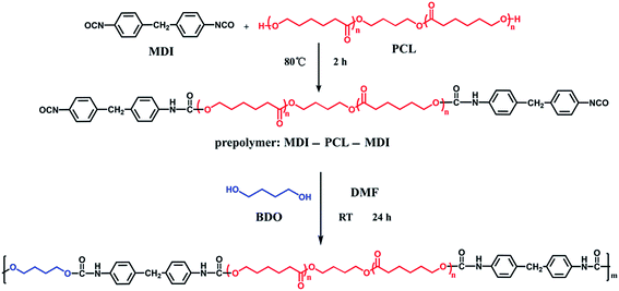
The linear polyurethane polymer was synthesized according to Scheme 1. First, a precursor was synthesized by the reaction of PCL and MDI (1![[thin space (1/6-em)]](https://www.rsc.org/images/entities/char_2009.gif) :
:![[thin space (1/6-em)]](https://www.rsc.org/images/entities/char_2009.gif) 2) at 80 °C under nitrogen atmosphere for 2 h. The precursor (16.0 g, 3.55 mmol) and 1,4-butylene glycol (BDO) (0.32 g, 3.55 mmol) were dissolved in anhydrous N,N-dimethylformamide (DMF, 90 mL) and then stirred at room temperature for 24 h. Eventually, 20 wt% PU solution was obtained.
2) at 80 °C under nitrogen atmosphere for 2 h. The precursor (16.0 g, 3.55 mmol) and 1,4-butylene glycol (BDO) (0.32 g, 3.55 mmol) were dissolved in anhydrous N,N-dimethylformamide (DMF, 90 mL) and then stirred at room temperature for 24 h. Eventually, 20 wt% PU solution was obtained.
Fabrication of porous-hollow PU microspheres
The experimental setup is shown in Fig. 1. The preparation system consists of a mechanical syringe pump loaded with a syringe, a high voltage generator and a grounded collector. In the electrospraying process, the 20 wt% PU solution was placed into a 5 mL syringe and was continuously pushed by the syringe pump at a flow rate of 14 mL h−1 to a right angle bended stainless steel nozzle with an internal diameter of 0.5 mm, which was connected to the high voltage power generator. The direct current high voltage generator was used to provide voltage of 8.5 kV potential differences between the nozzle and the grounded collector. A collecting bath of deionized water with 0.5 wt% tween 80 as the surfactant was used as the ground collector. The spraying distance between the nozzle and the collector was maintained at 10 cm. The obtained microspheres were washed with deionized water and centrifuged at 7000 rpm for five times to remove the Tween 80. At last, the microspheres were lyophilized using a freeze dryer.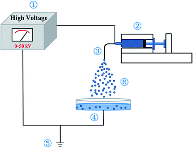 | ||
| Fig. 1 Schematic diagram of electrospraying apparatus. ① voltage generator; ② injection; ③ needle; ④ collection bath; ⑤ grounding device; ⑥ spraying droplets. | ||
Fabrication of PU microspheres with different sizes and morphologies
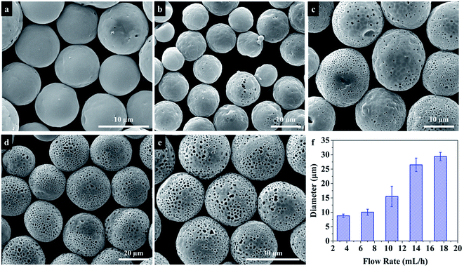
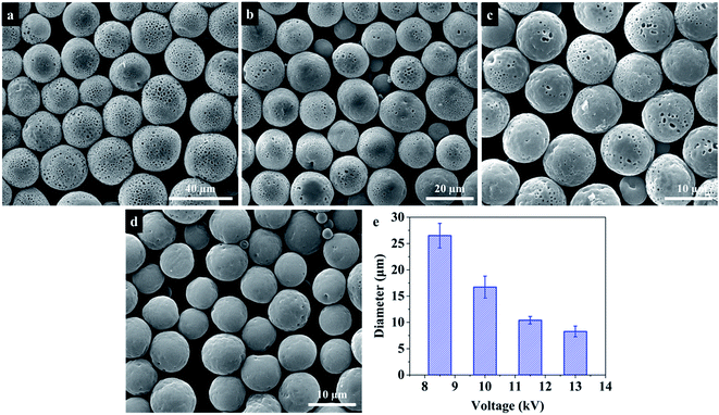
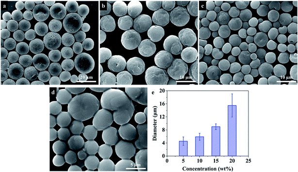
In order to fabricate PU microspheres with different sizes and morphologies, various electrospraying parameters that affect the formation of microspheres were investigated. To study the influence of solution concentration, different concentrations of PU solution (5 wt%, 10 wt%, 15 wt%, and 20 wt%) were used to prepare microspheres. Meanwhile, different flow rates (3.5 mL h−1, 7.0 mL h−1, 10.5 mL h−1, 14 mL h−1 and 17.5 mL h−1) and applied voltages (8.5 kV, 10.0 kV, 11.5 kV and 13.0 kV) to prepare microspheres were also studied, respectively. In addition, the influence of solvent, collection bath and collecting distance on the morphologies of PU microspheres was also investigated.Characterization
The weight average molecular weight (Mw) of the synthesized PU was determined by gel permeation chromatography (GPC; HLC-8320). For chemical structure analysis, PU was characterized by Fourier transform infrared spectrometer (FTIR; Nicolet 560) in the frequency range of 400–4000 cm−1, and the resolution and scanning number of FTIR test are 4 cm−1 and 32, respectively, and then further analyzed by using proton nuclear magnetic resonance spectrometer (1H NMR, Bruker ARX-400), operating at 400 MHz. Scanning electron microscopy (FEI, Quanta 250 field emission scanning electron microscope, SEM) was used to study the size and morphology of the fabricated PU microspheres. Before observation, the microspheres were dispersed in distilled water by ultrasonication and placed on a mica plate, then dried in a desiccator for 24 h. The particle diameter and pore size of PU microspheres were determined by image analysis using Image-Pro Plus Software (Media Cybernetics). To investigate the internal nanostructures, the microsphere aqueous solution was frozen by liquid nitrogen, and then broken into powder by a hammer. The powder was lyophilized using a freeze dryer, and the cross-section morphology of the microspheres was observed using SEM.Results and discussion
Synthesis and characterization of PU
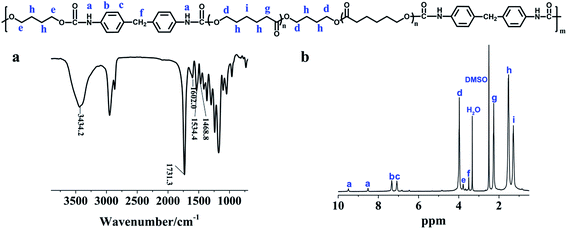
We used a two-step polycondensation method to prepare PU, as shown in Scheme 1. FTIR was used to characterize the molecular structure of PU. As shown in Fig. 2a, the peaks at ∼1468 cm−1, ∼1534 cm−1 and ∼1602 cm−1 belong to the absorption of C–H on the benzene ring. The peak at ∼1731 cm−1 is attributed to the absorption of carbamic acid ester groups. The peak of ∼3435 cm−1 can be assigned to the absorption of N–H. For the 1H NMR spectroscopy study, as shown in Fig. 2b, the peaks at 9.48 ppm and 8.52 ppm belong to the carbamate group, and the peak at 3.78 ppm belongs to the methine group in BDO. All of the above observations suggest the successful synthesis of the PU polymer. The results of GPC measurements show that the number average molecular weight (Mn), weight average molecular weight (Mw) and the polydispersity index (PDI) of the polyurethane are 29![[thin space (1/6-em)]](https://www.rsc.org/images/entities/char_2009.gif) 575, 54
575, 54![[thin space (1/6-em)]](https://www.rsc.org/images/entities/char_2009.gif) 836 and 1.85, respectively.
836 and 1.85, respectively.
Characterization of PU microspheres prepared by electrospraying
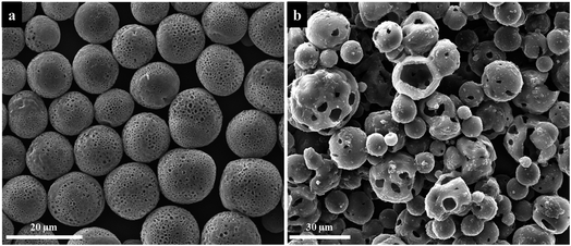
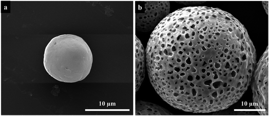
Fig. 3 are the SEM images of the PU microspheres fabricated by electrospraying. The microspheres were prepared from a 20 wt% PU solution with the following electrospraying parameters: the applied voltage is 8.5 kV and the flow rate is 17.5 mL h−1, while the collecting distance is 10 cm and the collection bath is deionized water. According to the SEM images, the microspheres exhibit spherical morphologies with an average diameter of ∼29 μm and a porous structure all over the surface. To investigate the internal structure, the cross-section of PU microspheres were observed, which displayed that the inner structure of PU microspheres is a hollow core with ∼23 μm diameter in Fig. 3c and d. The result indicates that a hollow core structure with a porous shell of PU microspheres could be generated by electrospraying without the assistance of any template.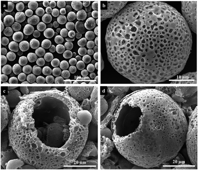 | ||
| Fig. 3 Low (a) and high (b) magnification SEM images and cross-section SEM images (c, d) of the obtained PU microspheres fabricated by electrospraying. | ||
The influence of experiment parameters on the size and morphology of PU microspheres
During the electrospraying process, the size and morphology of particles are controlled by electrospraying parameters, including solution physical properties such as surface tension, conductivity and viscosity, electrospraying distance, collection bath, strength of the electrostatic field, flow rate, and solution concentration. Some studies33,44 have investigated the influence of these electrospraying parameters on the size of polymer microspheres. However, these parameters also affect the solvent evaporation, which will further influence the morphology of PU microspheres. In order to obtain the PU microspheres with different sizes and morphologies, these parameters were investigated systematically in the following parts.| Solvent | Dielectric constant (at 20 °C) | Boiling point (°C) |
|---|---|---|
| DMF | 37.6 | 152.8 |
| THF | 7.52 | 66 |
| DCM | 8.9 | 39.8 |
The internal structure of PU microspheres
In above studies, we have discussed the influence of different electrospraying parameters on the size and surface morphology of PU microspheres. Now the factors to affect the internal structure of PU microspheres are investigated. By changing the flow rate when other parameters remained the same, PU microspheres with porous surface and smooth non-porous surface can be obtained as shown in Fig. 7. Fig. 11 shows the cross-section images of PU microspheres with different sizes and surface morphologies. To our surprise, the smallest microspheres with non-porous surface also have a hollow structure. When the non-porous surface of PU microspheres gradually transforms into a porous structure, the hollow internal structure always remains. Other electrospraying parameters, such as applied voltage and solution concentration, essentially influence the size of liquid particles sprayed from the Taylor cone, but not the formation process of the microspheres. Therefore, we can speculate that when using DMF as solvent, deionized water as the collection bath and the collecting distance is 10 cm, the smaller PU microspheres have hollow internal structure with non-porous surface, while the bigger PU microspheres have hollow internal structure with porous surface. Therefore, we can get the conclusion that hollow polyurethane microspheres with tunable surface structure were successfully prepared without any template by electrospraying.The possible formation mechanisms of hollow PU microspheres with porous and non-porous surface
According to the above results, we proposed the diffusion deposition–phase separation mechanism to explain the evolution process of the hollow PU microspheres with two different surface structures. The possible formation mechanisms are shown in Fig. 12. When the PU-DMF solution fragments to microdroplets, the surface of droplets is solidified due to the rapid solvent evaporation in the air. The PU segments inside the microdroplets continue to move to the surface and precipitate during the process of dropping from the needle tip to the collection bath, resulting in a hollow structure inside particles. Because the droplets are very small, most of the DMF solvent evaporates before the particles drop into the water bath, which attributes to the hollow microspheres with non-porous surface (Fig. 12A). The formation process of porous-hollow microspheres can be divided into two steps (Fig. 12B). The first step is rapid evaporation of DMF solvent and precipitation of PU segments as same as the formation process of hollow PU microspheres. With the increase of electrospraying flow rate or solution concentration, or the decrease of applied voltage, the diameter of microdroplets become bigger and the solvent evaporates incompletely before the particles drop into the collection bath. As water displays high solubility for DMF but it is anti-solvent for PU, When the PU/DMF particles drop into water, liquid–liquid phase separation occurs during rapid exchange of the DMF and water. After the completion of the exchange, the porous shell is formed. Eventually, the porous-hollow microspheres are obtained. The diffusion deposition–phase separation mechanism suggests that electrospraying technology also may be used in preparing other porous-hollow polymer microspheres. Compared with conventional methods such as template technique,24 double emulsion technique47 and coaxial electrospraying,40 electrospraying technology is a simple one-step method to prepare porous-hollow microspheres without other external assistant, and can easily tune the surface morphology of microspheres.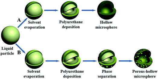 | ||
| Fig. 12 Schematic illustration of the two different kinds of PU microspheres formation mechanisms: (A) hollow microspheres with smaller size and (B) porous-hollow microspheres with bigger size. | ||
Conclusions
In conclusion, we have developed a novel one-step electrospraying technology to fabricate hollow PU microspheres with different surface structures. Their sizes and morphologies can be tuned by changing the electrospraying parameters, such as solvent, solution concentration, collection bath, flow rate and applied voltage. Two different kinds of PU microspheres with hollow structures can be obtained via adjusting the electrospraying parameters. A porous-hollow structure can be obtained by increasing flow rate or solution concentration, or decreasing applied voltage. The decrease of flow rate or solution concentration, or the increase of applied voltage leads to hollow structure with a non-porous surface. When the size of liquid droplets is bigger enough, the solvent does not evaporate completely before the particles drop into the collecting bath. The anti-solvent behavior generated in this process induces phase separation and causes a porous surface. While for smaller droplets, the solvent evaporates very fast and completely during the deposition process and leads to a non-porous surface. This work provides a general method to fabricate hollow polymer microspheres with tunable surface structures. The obtained hollow PU microspheres offer potential applications in many fields such as adsorbents, catalysis and drug delivery systems.Conflicts of interest
There are no conflicts to declare.Acknowledgements
This project was financially supported by the National Science Foundation of China (NSFC) under Grant No. 51703143 and the State Key Laboratory of Polymer Materials Engineering (Grant No. sklpme2017-3-04), and the starting fund of Sichuan University (Grant No. 20822041A4195).Notes and references
- G. Oertel and L. Abele, Polyurethane handbook: chemistry, raw materials, processing, application, properties, Hanser Publishers. Distributed in USA by Scientific and Technical Books, Macmillan, 1985 Search PubMed
.
- H.-W. Engels, H.-G. Pirkl, R. Albers, R. W. Albach, J. Krause, A. Hoffmann, H. Casselmann and J. Dormish, Angew. Chem., Int. Ed., 2013, 52, 9422–9441 CrossRef CAS PubMed
.
- L. Zhang, L. Chen and S. J. Rowan, Macromol. Chem. Phys., 2017, 218, 1600320 CrossRef
.
- P. V. Siva Reddy, G. N. Mahesh, S. Ramesh, P. A. Sivakumar and G. Radhakrishnan, J. Macromol. Sci., Part A: Pure Appl.Chem., 1995, 32, 789–799 CrossRef
.
- C.-Y. Lin and S.-h. Hsu, J. Biomed. Mater. Res., Part B, 2015, 103, 878–887 CrossRef PubMed
.
- M. Li and J. Xue, Langmuir, 2011, 27, 3229–3232 CrossRef CAS PubMed
.
- S. Budriene, T. Romaskevic, K. Pielichowski and J. Pielichowski, Polym. Adv. Technol., 2007, 18, 67–71 CrossRef CAS
.
- A. de Cuendias, R. Backov, E. Cloutet and H. Cramail, J. Mater. Chem., 2005, 15, 4196–4199 RSC
.
- E. Jabbari and M. Khakpour, Biomaterials, 2000, 21, 2073–2079 CrossRef CAS PubMed
.
- W. H. Guo, W. S. Wang, X. K. Yu, X. M. Peng and N. Y. Ma, RSC Adv., 2015, 5, 80568–80571 RSC
.
- G. Crotts and T. G. Park, J. Controlled Release, 1995, 35, 91–105 CrossRef CAS
.
- X. Peng and L. Zhang, Langmuir, 2005, 21, 1091–1095 CrossRef CAS PubMed
.
- X. W. Lou, L. A. Archer and Z. Yang, Adv. Mater., 2008, 20, 3987–4019 CrossRef CAS
.
- J. Fu, Z. Chen, X. Wu, M. Wang, X. Wang, J. Zhang, J. Zhang and Q. Xu, Chem. Eng. J., 2015, 281, 42–52 CrossRef CAS
.
- X. Zhu, S. Zhang, L. Zhang, H. Liu and J. Hu, RSC Adv., 2016, 6, 58511–58515 RSC
.
- J. Li, X. Lai, C. Xing and D. Wang, J. Nanosci. Nanotechnol., 2010, 10, 7707–7710 CrossRef CAS PubMed
.
- X. Liu, X. Jin and P. X. Ma, Nat. Mater., 2011, 10, 398–406 CrossRef CAS PubMed
.
- X. Liu, Y. Yang and M. W. Urban, Macromol. Rapid Commun., 2017, 38, 1700030 CrossRef PubMed
.
- C. Qi, Y.-J. Zhu, B.-Q. Lu, X.-Y. Zhao, J. Zhao and F. Chen, J. Mater. Chem., 2012, 22, 22642–22650 RSC
.
- S. Li, L. Nguyen, H. Xiong, M. Wang, T. C. C. Hu, J.-X. She, S. M. Serkiz, G. G. Wicks and W. S. Dynan, Nanotechnol. Biol. Med., 2010, 6, 127–136 CrossRef CAS PubMed
.
- Y. Ran, C. Wang, H. Li, J. Zhang, W. Ding and H. Xia, J. Nanosci. Nanotechnol., 2013, 13, 3004–3010 CrossRef CAS PubMed
.
- L. Li, J. Ding and J. Xue, Chem. Mater., 2009, 21, 3629–3637 CrossRef CAS
.
- J.-B. Fan, C. Huang, L. Jiang and S. Wang, J. Mater. Chem. B, 2013, 1, 2222–2235 RSC
.
- X. D. He, X. W. Ge, H. R. Liu, M. Z. Wang and Z. C. Zhang, Chem. Mater., 2005, 17, 5891–5892 CrossRef CAS
.
- Q. Qian, X. Huang, X. Zhang, Z. Xie and Y. Wang, Angew. Chem., Int. Ed., 2013, 52, 10625–10629 CrossRef CAS PubMed
.
- J. Lee, Y. J. Oh, S. K. Lee and K. Y. Lee, J. Controlled Release, 2010, 146, 61–67 CrossRef CAS PubMed
.
- X. Gong, W. Wen and P. Sheng, Langmuir, 2009, 25, 7072–7077 CrossRef CAS PubMed
.
- I. G. Loscertales, A. Barrero, I. Guerrero, R. Cortijo, M. Marquez and A. M. Gañán-Calvo, Science, 2002, 295, 1695–1698 CrossRef CAS PubMed
.
- J. Melcher and G. Taylor, Annu. Rev. Fluid Mech., 1969, 1, 111–146 CrossRef
.
- M. Cloupeau and B. Prunet-Foch, J. Electrost., 1989, 22, 135–159 CrossRef CAS
.
- M. Cloupeau and B. Prunet-Foch, J. Aerosol Sci., 1994, 25, 1021–1036 CrossRef CAS
.
- S. L. Shenoy, W. D. Bates, H. L. Frisch and G. E. Wnek, Polymer, 2005, 46, 3372–3384 CrossRef CAS
.
- P. Fattahi, A. Borhan and M. R. Abidian, Adv. Mater., 2013, 25, 4555–4560 CrossRef CAS PubMed
.
- A. Jaworek, Powder Technol., 2007, 176, 18–35 CrossRef CAS
.
- C. Hu, J. Zhao and W. Cui, J. Appl. Polym. Sci., 2013, 128, 3177–3183 CrossRef CAS
.
- S. D. Nath, S. Son, A. Sadiasa, Y. K. Min and B. T. Lee, Int. J. Pharm., 2013, 443, 87–94 CrossRef CAS PubMed
.
- D. Fantini, M. Zanetti and L. Costa, Macromol. Rapid Commun., 2006, 27, 2038–2042 CrossRef CAS
.
- N. Bock, M. A. Woodruff, D. W. Hutmacher and T. R. Dargaville, Polymers, 2011, 3, 131 CrossRef CAS
.
- X.-X. Wang, X.-J. Ju, S.-X. Sun, R. Xie, W. Wang, Z. Liu and L.-Y. Chu, RSC Adv., 2015, 5, 34243–34250 RSC
.
- M.-W. Chang, E. Stride and M. Edirisinghe, Langmuir, 2010, 26, 5115–5121 CrossRef CAS PubMed
.
- K. Pancholi, N. Ahras, E. Stride and M. Edirisinghe, J. Mater. Sci.: Mater. Med., 2009, 20, 917–923 CrossRef CAS PubMed
.
- C.-W. Chiu and P.-H. Lin, RSC Adv., 2016, 6, 67204–67211 RSC
.
- S. Vlad, C. Ciobanu, M. Butnaru, D. Macocinschi, D. Filip, L. M. Gradinaru and M. Mandru, Dig. J. Nanomater Biostruct., 2011, 6, 643–652 Search PubMed
.
- N. Bock, T. R. Dargaville and M. A. Woodruff, Prog. Polym. Sci., 2012, 37, 1510–1551 CrossRef CAS
.
- J. Yao, L. Kuang Lim, J. Xie, J. Hua and C.-H. Wang, J. Aerosol Sci., 2008, 39, 987–1002 CrossRef CAS
.
- N. Arya, S. Chakraborty, N. Dube and D. S. Katti, J. Biomed. Mater. Res., Part B., 2009, 88B, 17–31 CrossRef CAS PubMed
.
- S.-W. Choi, Y. Zhang and Y. Xia, Adv. Funct. Mater., 2009, 19, 2943–2949 CrossRef CAS PubMed
.
| This journal is © The Royal Society of Chemistry 2017 |

