 Open Access Article
Creative Commons Attribution 3.0 Unported Licence
Enhanced photoreduction of Cr(VI) and photooxidation of NO over TiO2−x mesoporous single crystals†
Yi Zhoua,
Wenzhang Fang a,
Yuanxin Denga,
Lihan Pana,
Bin Shena,
Hexing Lib,
Yun Hu
 c,
Haijun Chend,
Mingyang Xing*a and
Jinlong Zhang
 *a
*a
aKey Laboratory for Advanced Materials, Institute of Fine Chemicals, School of Chemistry and Molecular Engineering, East China University of Science and Technology, 130 Meilong Road, Shanghai 200237, PR China. E-mail: mingyangxing@ecust.edu.cn; jlzhang@ecust.edu.cn
bEducation Ministry Key Lab of Resource Chemistry, Shanghai Key Laboratory of Rare Earth Functional Materials, Department of Chemistry, Shanghai Normal University, Shanghai 200234, PR China
cSchool of Environment and Energy, South China University of Technology, Guangzhou 510006, PR China
dDepartment of Electronics and Tianjin Key Laboratory of Photo-Electronic Thin Film Device and Technology, Nankai University, Tianjin, 300071, China
First published on 11th December 2017
Abstract
Managing air and water pollution is among the greatest challenges and a major issue for human civilizations in the 21st century. Semiconductors such as TiO2 are regarded as one of the most promising catalysts that can be used to realize the simultaneous and efficient treatment of multi-component wastewater and NO selective oxidation. However, the granular TiO2 always contains too many phase interfaces, which are harmful to the transfer of photo-excited electrons. Reduced TiO2 mesoporous single crystals (TiO2−x MSCs) with capacity of photoreduction and photooxidation were successfully synthesized by a facile hydrothermal treatment. The formation of Ti3+ impurity levels contribute to a narrowed band gap and enhanced visible light adsorption of TiO2−x. In addition, the mesoporous single crystal structure would provide a long-range order channel for the transfer of photo-generated electrons, which leads to the efficient photoreduction and photooxidation capacity of TiO2−x MSCs. The results revealed that Ti3+-MSCs exhibit outstanding photocatalytic decontamination performance in simultaneous photo-degradation of phenol and removal of Cr(VI) owing to high photo-generated charge separation rate and the synergistic effect of phenol and Cr(VI). In addition, in the absence of any noble metal, the as-prepared reduced Ti3+-MSCs still show high selectivity of NO2 in the NOx photo-oxidation process, owing to the extended wide-spectrum absorption of Ti3+-MSCs and the high-active holes on Ti3+-MSCs under solar light irradiation.
Introduction
Photo-decontamination for the removal of toxic substances in wastewater from industrial processes such as leather tanning, electroplating and dyeing industries remains a huge challenge.1 These toxic substances contain both organic and inorganic pollutants. The primary organic pollutants are aromatic hydrocarbons, such as phenols,2,3 1,4-dichlorobenzene,4 tetracycline and rhodamine B5 and the primary inorganic pollutants are heavy metals, such as Cr(VI),6,7 Hg(II),8 and Pd(II).9 These pollutants pose a serious threat to human beings and other species because of their teratogenicity, carcinogenicity and bio-toxicity.10 The simultaneous removal of organic matter and toxic heavy metal ions from wastewater has particular significance to pollution control and decontamination.11–15 Cr(VI) and phenol are two typical environmental contaminants that are widely used in industrial and military production.16 The simultaneous reduction of hexavalent chromium (Cr(VI)) and oxidation of phenol has attracted plenty of attention.17,18 In this respect, Cr(VI) could be photo-reduced to the less harmful Cr(III)6,19 and phenol could be photo-oxidized into carbon dioxide or other eco-friendly organic matter by photocatalysts.2,20 Moreover, because of the high oxidation capacity of Cr(VI), it can be easily reduced by reductants such as sodium bisulfite.21 Nevertheless, a reductant dose larger than the stoichiometric amount has to be used for effective reduction. Adversely, secondary pollution is often caused. Alternatively, photocatalysts are regarded as an eco-friendly and efficient solution to this problem. To date, plenty of research has been reported on simultaneous removal of Cr(VI) and phenol by the TiO2-based photocatalysis process. In our previous study,3 mesoporous TiO2 single crystals (MSCs) were considered as ideal photo-catalysts for simultaneous photo-decontamination of wastewater containing phenol and Cr(VI) owing to their perfect single crystalline structures, catalytically active facets and large surface areas. However, the photocatalytic activities of TiO2 MSCs are limited by their relatively wide band gap (3.2 eV) and the high recombination rate of the photo-generated charges.2,22,23Moreover, air pollution also poses a serious threat to the eco-system. Nitric oxide (NOx) pollutants are primarily responsible for acid precipitation, photo-chemical smog, and ozone depletion.24 There two most common compounds of the nitric oxide group are NO25 and NO2.26 The majority of nitric oxide emissions result from industrial furnaces, fossil fuel burning and internal combustion engines.27 Therefore, the development of new methods to control NOx emission has attracted much attention in recent years. However, these methods usually require high temperatures and specific equipment, which are not economical choices and could cause secondary pollution. Therefore, photocatalytic NO oxidation is regarded as an ideal method owing to its low-cost, facile reaction conditions and eco-friendliness. In general, there are three types of catalysts for NO oxidation: noble metal catalysts,28,29 metal oxides catalysts30 and ion-exchanged zeolites.31 Hence, TiO2 MSCs are regarded as promising photocatalysts for selective oxidation in the gas phase.
Herein, reduced TiO2 mesoporous single crystals (Ti3+-MSCs) with stable titanous doping were successfully synthesized by a facile hydrothermal treatment. They had a stable blue appearance because of the generation of Ti3+ and oxygen vacancies. The Ti3+ impurity level below the conduction band contributes to the narrowing of the band gap and extended absorption of solar light. By the in situ self-modification of MSCs, an outstanding photocatalytic decontamination performance for simultaneous photo-degradation of phenol and Cr(VI) can be achieved. Furthermore, new applications in environmental protection such as high activity and selectivity of NO2 in NOx photo-oxidation process can also be realized.
Experimental
Materials and methods
Characterizations
The phase compositions of all catalysts were determined in air by powder X-ray diffraction measurements (XRD) using a Rigaku Ultima IV diffraction meter equipped with Cu Kα radiation (λ = 1.5406 Å). Data were collected while varying 2θ between 10 and 80°. The Raman spectra measurements were recorded with a Renishaw inVia Reflex Raman spectrometer with 524.5 nm laser excitation. The morphologies of all the composites were characterized by transmission electron microscopy (JEM-2100, JEOL) and field emission scanning electron microscopy (FESEM, Nova Nano-SEM 450). The electron paramagnetic resonance (EPR) spectra were recorded on a Bruker EMX 8/2.7 EPR spectrometer at an X-band frequency of 9.464 GHz, a sweep width of 1000.00 Gauss, and a center field of 3450.00 Gauss. The shift of the binding energy was referenced to the C1s level at 284.6 eV as an internal standard. The ultraviolet-visible (UV-vis) diffuse reflectance spectra (DRS) were measured on a SHIMADZU UV-2600 spectrometer equipped with an integrating sphere assembly and using BaSO4 as the reference sample. The photoluminescence (PL) emission spectra of the solid catalysts were also recorded at room temperature (25 °C) using luminescence spectrometry (Cary Eclipse) under the excitation light at 310 nm. All the electrochemical experiments were carried out at room temperature in a cell with a standard three-electrode system using an electrochemical analyzer (CHI 660 D electrochemical station, CHI Instruments Inc.). The electrode system consisted of a working electrode (as-prepared samples as the working electrodes with an active area of ca. 0.5 cm−2), a Pt wire as the counter electrode and a saturated Ag/AgCl as the reference electrode. Transient photocurrent responses of different samples were studied in 0.5 M Na2SO4 aqueous solution under various irradiation conditions (300 W Xe lamp).Photoreduction and photooxidation tests
![[thin space (1/6-em)]](https://www.rsc.org/images/entities/char_2009.gif) :
:![[thin space (1/6-em)]](https://www.rsc.org/images/entities/char_2009.gif) 1, 20 μL mixture of H3PO4 and water volume ratio of 1
1, 20 μL mixture of H3PO4 and water volume ratio of 1![[thin space (1/6-em)]](https://www.rsc.org/images/entities/char_2009.gif) :
:![[thin space (1/6-em)]](https://www.rsc.org/images/entities/char_2009.gif) 1 and 3.5 mL sample solution). The solution was blended well and kept standing for 15 min before the analysis. The absorbance measurements at 540 nm were performed using a UV-vis spectrophotometer (SHIMADZU UV-2600).
1 and 3.5 mL sample solution). The solution was blended well and kept standing for 15 min before the analysis. The absorbance measurements at 540 nm were performed using a UV-vis spectrophotometer (SHIMADZU UV-2600).| Total NOx removal (μmol g−1) = NO removal − yield of NO2 |
Results and discussion
The TEM and FESEM images of Ti3+-MSCs are shown in Fig. 1a and b, respectively. The images show that the obtained Ti3+-MSCs exhibit a tetragonal bipyramid profile and an ordered mesoporous structure with a size of 700–800 nm, which is consistent with the result of the low-magnified FESEM (Fig. S1†). The pore size of the Ti3+-MSCs is about 45 nm. The type IV N2 sorption isotherm curves and the Barrett–Joyner–Halenda pore size distribution centered at 40–50 nm confirm the mesoporous nature of the structure (Fig. S2†). The magnified image of Ti3+-MSCs is shown in Fig. 1c. It indicates that the edges of Ti3+-MSCs are relatively smooth. The corresponding selected area electron diffraction (SAED) patterns in the insets of Fig. 1c confirm that Ti3+-MSCs are single crystal structured.33 The diffraction lattice matrix of (110) is parallel to the {110} facets and vertical to the diffraction lattice matrix of (001), which indicates that TiO2 prefers to form a [001]-oriented tetragonal rutile single crystal with dominant {110} facets owing to the influence of HCl in lowering the activation energy for the rutile formation. The (101) facets can be observed in HRTEM (Fig. 1d). All the lattice fringes have long-term orderly arrangements, indicating the single crystalline nature of Ti3+-MSCs, which implies the capacities of MSCs for high electron mobility.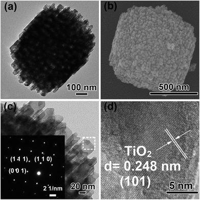 | ||
| Fig. 1 (a) TEM image of Ti3+-MSCs, (b) FESEM image of Ti3+-MSCs, (c) and (d) HRTEM image of Ti3+-MSCs. Insets of (c) shows the corresponding SAED pattern of Ti3+-MSCs. | ||
The crystalline structures of Ti3+-MSCs and MSCs were investigated by XRD. As shown in Fig. 2a, the XRD patterns of Ti3+-MSCs and MSCs show almost the same peaks, which can be indexed to the characteristic diffraction peaks of rutile TiO2 (JCPDS 12-1276). In addition, Ti3+-MSCs and MSCs exhibit strong diffraction peaks, indicating that the obtained catalysts have high crystallinity. The blue Ti3+-MSCs were calcinated in air to obtain the white MSCs. Compared with that of MSCs, the absorption shoulder of Ti3+-MSCs shows a significant red-shift (Fig. 2b). The absorption intensity in the range of 400–700 nm of Ti3+-MSCs clearly increases with titanous doping. The color of Ti3+-MSCs was blue, while MSCs turned to be white. This could be attributed to the generation of Ti3+ and oxygen vacancies in the bulk or on the surface of the Ti3+-MSCs.34,35 This result is consistent with other studies that have been reported previously.36 Moreover, the bandgap of Ti3+-MSCs also has a distinct decrease from 3.09 eV to 3.01 eV compared with that of MSCs, implying that the formation of the Ti3+ impurity level contributes to the narrowing of the bandgap of Ti3+-MSCs.
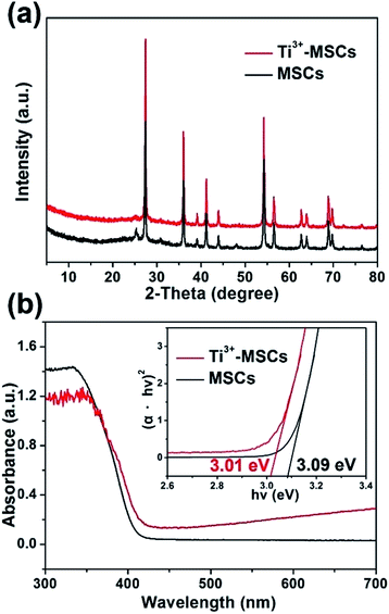 | ||
| Fig. 2 (a) XRD spectra of MSCs and Ti3+- MSCs, and (b) UV-vis DRS spectra and transformed Kubelka–Munk function against the photon energy plot (inset) of MSCs and Ti3+-MSCs. | ||
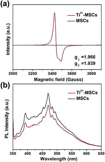
In order to investigate the reason of the enhancement of visible light absorption over Ti3+-MSCs, we performed EPR test on each sample (Fig. 3a). MSCs show no Ti3+ signals in the EPR spectra owing to the oxidation of Ti3+ during the calcination process. The EPR signals of Ti3+-MSCs with g⊥ = 1.966 and g∥ = 1.939 were observed, which should be ascribed to the Ti3+ species in the bulk of TiO2.37,38 The strong Ti3+ signals of Ti3+-MSCs in low temperature EPR imply high concentration of Ti3+ in the catalyst.39,40 Moreover, because the EPR signals and the g-value of rutile are different from those of the anatase, the results confirm the rutile phase of the as-prepared sample.41 Moreover, photoluminescence (PL) emission spectra analysis was used to better understand the transfer and recombination process of photogeneration charges in the semiconductor photocatalyst (Fig. 3b). The intensity of PL increases immediately after calcination, so MSCs have a higher PL signal than Ti3+-MSC. Compared with the MSCs, the Ti3+ doping catalysts exhibit lower PL intensity of around 370 nm and 475 nm, indicating low recombination rate of the photo-generated electron–hole pairs, and higher photoactivity. It is reasonable to ascribe the lower recombination of electrons and holes to the capture of holes by surface oxygen vacancy and defects.42,43 Therefore, more electrons would remain and participate in the photoreduction process, which predicates a higher photoreduction activity of Ti3+-MSCs. The trapping holes in oxygen vacancies act as an active site for the photo-oxidation process.
The simultaneous photo-degradation of phenol and removal of Cr(VI) under solar light illumination were evaluated to analyze the synergistic photocatalytic decontamination between phenol and Cr(VI) (Fig. 4). According to the previous report,44 the Cr(VI) reduction efficiencies were good at pH ≤ 4, particularly showing highest reduction efficiencies at pH = 2.3. In the synchronous removal of phenol and Cr(VI) test, however, we employed UV-vis spectrophotometry and HPLC to measure the concentration of Cr(VI) and phenol over one solution at the same time, respectively. A low pH value shows some disadvantages of the HPLC test for phenol. Hence, the suitable pH value for the photocatalytic removal of Cr(VI) in our study was recommended as 4.0. In addition, the chromium ions (Cr2O72−) of H2Cr2O7 resulted in low pH values and the photo-removal process of Cr(VI) took place as shown in eqn (1):44
| Cr2O72− + 14H+ + 6e− → 2Cr(III) + 7H2O | (1) |
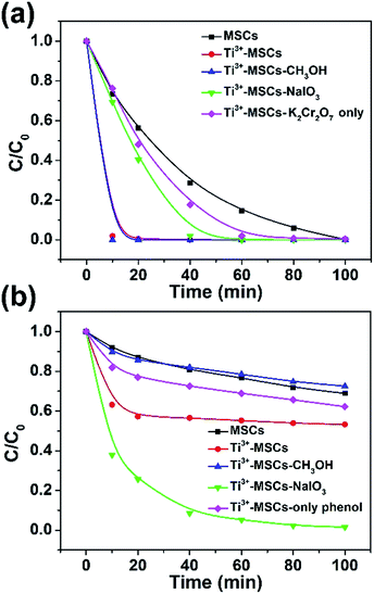 | ||
| Fig. 4 The synchronous photocatalytic degradation dynamics of (a) Cr(VI) and (b) phenol over different catalysts under simulated solar light irradiation (with an AM 1.5 air mass filter). | ||
As shown in the equation above, the existence of abundant H+ is advantageous to the photocatalytic removal of Cr(VI). Fig. 4a demonstrates the photocatalytic reduction of Cr(VI) over a variety of as-prepared catalysts at pH = 4.0. Ti3+-MSCs show much higher photo-reduction activity than MSCs. The photoreduction rate of Cr(VI) over Ti3+-MSCs without phenol was slower than that with phenol. The existence of phenol could enhance the removal of Cr(VI) by acting as the scavenger of photo-generated holes. Moreover, an electron or hole trapping agent was added into the reaction solution to investigate synergistic photocatalytic decontamination between phenol and Cr(VI) processes. Upon addition of the electron trapping agent (sodium iodate, NaIO3) to the solution containing Ti3+-MSCs, the photo-reduction activity of Cr(VI) for Ti3+-MSCs significantly decreases, indicating that irradiated Ti3+-MSCs have higher active electron concentration. Nevertheless, the removal activity of Cr(VI) for the Ti3+ doped sample has no significant change when the hole trapping agent (methanol, CH3OH) was injected, indicating the electrons would directly involve in the Cr(VI) reduction reaction. For photo-oxidation of phenol (Fig. 4b), Ti3+-MSCs exhibit higher activity than MSCs. The photodegradation rate of phenol over Ti3+-MSCs without Cr(VI) was slower than that with Cr(VI). This indicated that the existence of Cr(VI) could promote the degradation of phenol by acting as a sacrificial agent of holes. Upon addition of CH3OH, however, the oxidation rate of phenol for Ti3+-MSCs reduces sharply, indicating that irradiated Ti3+-MSCs generate more holes in the phenol-oxidation process. In addition, the electron trapping agent, NaIO3, shows remarkable promotion effect in the photo-degradation process of phenol, indicating that the holes were not directly involved in the phenol oxidation. The holes were reacted with H2O molecules to generate the hydroxyl radicals, which are responsible for the photooxidation of phenol. The addition of NaIO3 would trap the electrons and prolong the lifetime of holes to produce abundant hydroxyl radicals. Interestingly, when the concentration of Cr(VI) reduced to nearly zero, the photo-oxidation rate of phenol decreased sharply (red line fixed at 10 min and green line fixed at 40 min, as shown in Fig. 4a and b), indicating that the presence of Cr(VI) promoted the oxidation rate of phenol.44 This result is ascribed to the synergistic effect between the photo-oxidation of phenol and the photo-reduction of Cr(VI).9
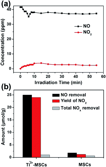
Photooxidation of NO gas under solar light was used to evaluate the gas photocatalytic activities of the as-prepared Ti3+-MSCs (Fig. 5). The light was turned on after NO adsorption–desorption equilibrium was achieved. Since the light was turned on, the concentration of NO decreased sharply and the concentration of NO2 simultaneously increased (Fig. 5a). However, the increase in NO2 concentration is very slow. The chemisorption of NO caused by photogenerated hydroxyl radicals leads to the plunge in the concentration of NO.45 It is worth noting that the concentration of NO does not reduce, which indicates that the adsorption saturation has been reached. Then, the concentration of NO2 increases with the illumination time. After 10 min of light irradiation, the gas concentrations varied slowly. Moreover, all nitrogen in the gas phase approximately achieves equilibrium after 60 min of irradiation as shown in eqn (2).
| NOout (37.0 ppm) + NO2 out (4.0 ppm) ≈ NO in (41 ppm) | (2) |
MSCs and Ti3+-MSCs were evaluated for photo-decontamination of NOx experiments to illustrate that the Ti3+ doping benefits the oxidation of NOx (Fig. 5b). The NO removal amount within 60 min over Ti3+-MSCs is 10 times as high as that over MSCs. Moreover, the yield of NO2 within one hour over Ti3+-MSCs is about 9 times higher than that over MSCs. The higher the percentage of NO transformed to NO2, the lower is total NOx removal. In other words, the selectivity of NO2 is high over Ti3+-MSCs. This could be attributed to the high separation rate of the photo-generated electrons and holes from irradiated Ti3+-MSCs. In other words, the active holes sites efficiently promote the oxidation of NO.
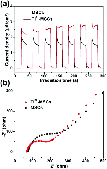
In order to investigate the mechanism of photoreduction and photooxidation over Ti3+-MSCs, the photoelectrochemical properties of these samples were also measured by transient photocurrent test under solar light irradiation as shown in Fig. 6a. The rise and fall of the photocurrent corresponded to the switching on and off of irradiation. Both samples show stable current intensity. However, the transient photocurrent of Ti3+-MSCs is 1.5 times higher than that of MSCs. This result reveals the enhanced light absorption properties of Ti3+-MSCs, which attribute to the higher separation rate of electrons and holes of Ti3+-MSCs and its remarkable charge transfer ability owing to its long-range order crystallinity.34,46 In addition, to validate our postulate that improved separation rate of photo-generated charges contributes to a better performance, we compared the electrochemical impedance spectra (EIS) of Ti3+-MSCs and MSCs in dark. The semicircle in the Nyquist plots of Ti3+-MSCs is significantly smaller than that of MSCs (Fig. 6b). In other words, the impedance of Ti3+-MSCs is distinctly smaller than that of MSCs, suggesting a higher separation rate of electrons and holes and an excellent charge transfer process. This result is associated directly with a more efficient charge transfer process and better photoreduction and photooxidation activity over Ti3+-MSCs.47
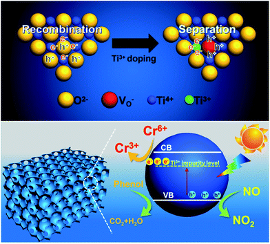
The proposed mechanism of synergistic photocatalytic decontamination between phenol and Cr(VI) on Ti3+-MSCs is illustrated in Fig. 7. After Ti3+ doping, the generation of abundant Ti3+ leads to the formation of the Ti3+ impurity level under the conduction band (CB) of the mesoporous titanium dioxide single crystal, which contributes to a narrowed band gap and also an extended solar light absorption of TiO2-MSCs to the visible light region. Ti3+-MSCs efficiently utilize the visible light in the photo-redox reaction. In addition, TiO2−x mesoporous single crystals are excited by solar light to generate electrons and holes, and some of the holes are captured by the oxygen vacancy (top of Fig. 7). This leads to high separation efficiency of electrons and holes, and the longer lifetime of electrons. This can be confirmed by the results of photoluminescence (PL) emission spectra analysis. Subsequently, electrons can directly participate in the reduction of Cr(VI). Therefore, in our designed system, Ti3+-MSCs exhibit an excellent performance in simultaneous photodegradation of phenol and removal of Cr(VI) in liquid state reaction, owing to the synergistic effect of Cr(VI) and phenol. Furthermore, for Ti3+-MSCs, as more active holes are involved in the oxidation of NO, higher activity is obtained owing to its low recombination rate of electrons and holes.
Conclusions
A blue reduced titanium dioxide mesoporous single crystal with Ti3+ doping was synthesized using a simple hydrothermal method. According to the results of the EPR measurements, the amount of Ti3+ species of Ti3+-MSCs is higher than MSCs. The self-doping of Ti3+ contributes to the formation of impurity levels just below the conduction band, which results in the narrowing of the band gap. Moreover, the oxygen vacancies in Ti3+-MSCs lead to a high photo-generated charge separation rate and prolonged lifetime of the electrons. Hence, the obtained Ti3+-MSCs present an extended wide-spectrum light absorption in the range of 400–700 nm and high capacities for electron mobility. The obtained metal-free Ti3+-MSCs exhibit outstanding photocatalytic decontamination performance in simultaneous removal of phenol and Cr(VI). The active electrons of Ti3+-MSCs, high photo-generated charges separation rate and synergistic effect between phenol and Cr(VI) lead to these high decontamination abilities. Furthermore, high-concentrated oxygen vacancies of Ti3+-self doped MSCs lead to an improved selectivity of NO2 in the NOx photo-oxidation process.Conflicts of interest
The authors declare no competing financial interest.Acknowledgements
This work was supported by the National Natural Science Foundation of China (21577036, 21377038, 21237003, 21677048), State Key Research Development Program of China (2016YFA0204200), the “Chenguang Program” from Shanghai Education Development Foundation and Shanghai Municipal Education Commission (14CG30), Science and Technology Commission of Shanghai Municipality (16JC1401400, 17520711500), Shanghai Pujiang Program (17PJD011), and the Fundamental Research Funds for the Central Universities (22A201514021).References
- R. Qiu, D. Zhang, Z. Diao, X. Huang, C. He, J.-L. Morel and Y. Xiong, Water Res., 2012, 46, 2299–2306 CrossRef CAS PubMed.
- Y. Zhou, Q. Yi, M. Xing, L. Shang, T. Zhang and J. Zhang, Chem. Commun., 2016, 52, 1689–1692 RSC.
- T. Wang, Z.-y. Xu, L.-g. Wu, B.-r. Li, M.-x. Chen, S.-y. Xue, Y.-c. Zhu and J. Cai, RSC Adv., 2017, 7, 31921–31929 RSC.
- Y. Tae Kwon, K. Yong Song, W. In Lee, G. Jin Choi and Y. Rag Do, J. Catal., 2000, 191, 192–199 CrossRef.
- L. Zhou, L. Wang, J. Zhang, J. Lei and Y. Liu, Res. Chem. Intermed., 2017, 43, 2081–2101 CrossRef CAS.
- D. Lu, W. Chai, M. Yang, P. Fang, W. Wu, B. Zhao, R. Xiong and H. Wang, Appl. Catal., B, 2016, 190, 44–65 CrossRef CAS.
- Y. Yang, G. Wang, Q. Deng, H. Wang, Y. Zhang, D. H. L. Ng and H. Zhao, RSC Adv., 2014, 4, 34577–34583 RSC.
- G. Chi, B. Shen, R. Yu, C. He and X. Zhang, J. Hazard. Mater., 2017, 330, 83–92 CrossRef CAS PubMed.
- D. Lu, M. Yang, P. Fang, C. Li and L. Jiang, Appl. Surf. Sci., 2017, 399, 167–184 CrossRef CAS.
- H. Qin, Y. Bian, Y. Zhang, L. Liu and Z. Bian, Chin. J. Chem., 2017, 35, 203–208 CrossRef CAS.
- Y. Choi, M. S. Koo, A. D. Bokare, D.-h. Kim, D. W. Bahnemann and W. Choi, Environ. Sci. Technol., 2017, 51, 3973–3981 CrossRef CAS PubMed.
- L. Wang, N. Wang, L. Zhu, H. Yu and H. Tang, J. Hazard. Mater., 2008, 152, 93–99 CrossRef CAS PubMed.
- S. Dong, J. Feng, M. Fan, Y. Pi, L. Hu, X. Han, M. Liu, J. Sun and J. Sun, RSC Adv., 2015, 5, 14610–14630 RSC.
- P. K. Boruah, P. Borthakur, G. Darabdhara, C. K. Kamaja, I. Karbhal, M. V. Shelke, P. Phukan, D. Saikia and M. R. Das, RSC Adv., 2016, 6, 11049–11063 RSC.
- K. Kabra, R. Chaudhary and R. L. Sawhney, Ind. Eng. Chem. Res., 2004, 43, 7683–7696 CrossRef CAS.
- R. Vinu and G. Madras, Environ. Sci. Technol., 2008, 42, 913–919 CrossRef CAS PubMed.
- H.-M. Zhang, W. Xu, Z. Fan, X. Liu, Z.-C. Wu and M.-H. Zhou, Sep. Purif. Technol., 2017, 172, 152–157 CrossRef CAS.
- O. M. Ontañon, P. S. González, G. G. Barros and E. Agostini, New Biotechnol., 2017, 37, 172–179 CrossRef PubMed.
- H. Chen, Y. Shao, Z. Xu, H. Wan, Y. Wan, S. Zheng and D. Zhu, Appl. Catal., B, 2011, 105, 255–262 CrossRef CAS.
- V. Makrigianni, A. Giannakas, C. Daikopoulos, Y. Deligiannakis and I. Konstantinou, Appl. Catal., B, 2015, 174, 244–252 CrossRef.
- G. Qin, M. J. McGuire, N. K. Blute, C. Seidel and L. Fong, Environ. Sci. Technol., 2005, 39, 6321–6327 CrossRef CAS PubMed.
- Y. Zhang, Z.-R. Tang, X. Fu and Y.-J. Xu, ACS Nano, 2010, 4, 7303–7314 CrossRef CAS PubMed.
- C. Dong, H. Song, Y. Zhou, C. Dong, B. Shen, H. Yang, M. Matsuoka, M. Xing and J. Zhang, RSC Adv., 2016, 6, 77863–77869 RSC.
- N. Tang, Y. Liu, H. Wang and Z. Wu, J. Phys. Chem. C, 2011, 115, 8214–8220 CAS.
- M. Ghafari and J. D. Atkinson, Environ. Sci. Technol., 2016, 50, 5189–5196 CrossRef CAS PubMed.
- I. Papailias, N. Todorova, T. Giannakopoulou, J. Yu, D. Dimotikali and C. Trapalis, Catal. Today, 2017, 280, 37–44 CrossRef CAS.
- K. Skalska, J. S. Miller and S. Ledakowicz, Sci. Total Environ., 2010, 408, 3976–3989 CrossRef CAS PubMed.
- D. Bhatia, R. W. McCabe, M. P. Harold and V. Balakotaiah, J. Catal., 2009, 266, 106–119 CrossRef CAS.
- J. Jelic, K. Reuter and R. Meyer, ChemCatChem, 2010, 2, 658–660 CrossRef CAS.
- J. Giménez-Mañogil, A. Bueno-López and A. García-García, Appl. Catal., B, 2014, 152, 99–107 CrossRef.
- M. Iwamoto, H. Furukawa, Y. Mine, F. Uemura, S.-i. Mikuriya and S. Kagawa, J. Chem. Soc., Chem. Commun., 1986, 1272–1273, 10.1039/C39860001272.
- Y. Hu, X. Song, S. Jiang and C. Wei, Chem. Eng. J., 2015, 274, 102–112 CrossRef CAS.
- H. G. Yang, C. H. Sun, S. Z. Qiao, J. Zou, G. Liu, S. C. Smith, H. M. Cheng and G. Q. Lu, Nature, 2008, 453, 638–641 CrossRef CAS PubMed.
- W. Fang, L. Khrouz, Y. Zhou, B. Shen, C. Dong, M. Xing, S. Mishra, S. Daniele and J. Zhang, Phys. Chem. Chem. Phys., 2017, 19, 13875–13881 RSC.
- Y. Zhou, Y. Liu, P. Liu, W. Zhang, M. Xing and J. Zhang, Appl. Catal., B, 2015, 170–171, 66–73 CrossRef CAS.
- F. Zuo, L. Wang, T. Wu, Z. Zhang, D. Borchardt and P. Feng, J. Am. Chem. Soc., 2010, 132, 11856–11857 CrossRef CAS PubMed.
- L. Bonneviot and G. L. Haller, J. Catal., 1988, 113, 96–105 CrossRef CAS.
- W. Fang, M. Xing and J. Zhang, J. Photochem. Photobiol., C, 2017, 32, 21–39 CrossRef CAS.
- W. Fang, Y. Zhou, C. Dong, M. Xing and J. Zhang, Catal. Today, 2016, 266, 188–196 CrossRef CAS.
- W. Fang, M. Xing and J. Zhang, Appl. Catal., B, 2014, 160–161, 240–246 CrossRef CAS.
- M. Liu, X. Qiu, M. Miyauchi and K. Hashimoto, Chem. Mater., 2011, 23, 5282–5286 CrossRef CAS.
- J. Yu, J. Fan and B. Cheng, J. Power Sources, 2011, 196, 7891–7898 CrossRef CAS.
- J. Su, X. Zou and J.-S. Chen, RSC Adv., 2014, 4, 13979–13988 RSC.
- F. Liu, J. Yu, G. Tu, L. Qu, J. Xiao, Y. Liu, L. Wang, J. Lei and J. Zhang, Appl. Catal., B, 2017, 201, 1–11 CrossRef CAS.
- G. Guo, Y. Hu, S. Jiang and C. Wei, J. Hazard. Mater., 2012, 223, 39–45 CrossRef PubMed.
- Z. Bian, T. Tachikawa and T. Majima, J. Phys. Chem. Lett., 2012, 3, 1422–1427 CrossRef CAS PubMed.
- C. Mao, F. Zuo, Y. Hou, X. Bu and P. Feng, Angew. Chem., Int. Ed., 2014, 53, 10485–10489 CrossRef CAS PubMed.
Footnote |
| † Electronic supplementary information (ESI) available. See DOI: 10.1039/c7ra09903g |
| This journal is © The Royal Society of Chemistry 2017 |


