 Open Access Article
Study on preparation conditions of coal fly ash catalyst and catalytic mechanism in a heterogeneous Fenton-like process
Nannan Wang *ab,
Jiaqing Chenab,
Qiang Zhaoc and
Han Xua
aSchool of Mechanical Engineering, Beijing Institute of Petrochemical Technology, Beijing 102617, PR China. E-mail: wnn_flying@163.com
bBeijing Key Laboratory of Pipeline Critical Technology and Equipment for Deepwater Oil & Gas Development, Beijing 102617, PR China
cBeijing BHT Environment Technology Co., Ltd, Beijing 100102, PR China
First published on 13th November 2017
Abstract
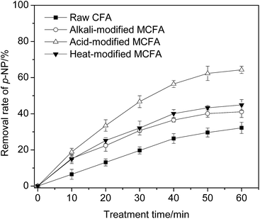
Coal fly ash (CFA) was transformed into three kinds of heterogeneous Fenton-like catalysts (MCFA powder, granular MCFA and Fe2O3/granular MCFA). The study results show that different types of CFA have different initial catalytic performances and acid modification can activate CFA better (64.3% of p-NP removal rate) than other methods (alkali (41.1%) and heat (44.9%) modification). Compared with kaoline, attapulgite can produce better granular MCFA (43.1% (attapulgite) versus 28.6% (kaoline)) by bonding MCFA powder together, and the optimal calcination temperature is 723 K. Supporting Fe2O3 on the surface of granular MCFA can promote the performance of granular MCFA significantly. The precursor solution (Fe(NO3)3) with pH pre-adjusted by oxalate can produce a relatively good Fe2O3/granular MCFA catalyst and 12 h of impregnation is recommended. Calcining the impregnated granular MCFA at 673 K for 2 h is the last necessary step in preparing Fe2O3/granular MCFA. The three MCFA catalysts could be reused at least 3 times, with a 57% removal rate of COD, even if real secondary effluent was treated. The CFA and three MCFA catalysts were characterized and their catalytic mechanism in a heterogeneous Fenton-like process was proposed.
1. Introduction
Advanced oxidation processes (AOPs) are among the most effective physical–chemical methods for treating organic wastewater. The common feature of AOPs is the generation of hydroxyl radicals (·OH) that can effectively decompose refractory organics due to their strong oxidation (E0 = 2.8 V).1,2 The Fenton process, as the classic AOP, can generate ·OH via the reaction of Fe2+ with H2O2. The main reactions in Fenton processes are shown as eqn (1) and (2):3| Fe2+ + H2O2 → Fe3+ + OH− + ˙OH | (1) |
| ˙OH + organics → intermediates → inorganics | (2) |
Some studies4,5 show that recycling of the homogeneous catalyst (Fe2+) cannot be achieved easily, leading to the generation of sludge containing Fe ions. The treatment of the sludge is expensive in labour, reagents, and time. In order to utilize the strong oxidation of the Fenton process, the above disadvantage must be overcome.
Coal fly ash (CFA) is a solid waste produced from coal-burning power plants and steel mills, and more than 300 billion tons of CFA can be produced every year in the world.6 Traditionally, landfill is the most frequently used method for the treatment of CFA. However, this treatment method always causes severe environmental problems, due to the leaching of metallic ions into the soil/groundwater and the diffusion of CFA into the air. It is imperative to explore a method for the proper treatment/application of CFA.
Over the years, many studies7–12 have found that the crystalline phases that contain the iron element in CFA can replace Fe2+ to catalyse the Fenton-like process. Thus, it is beneficial to activate CFA into a solid catalyst for the application of CFA in wastewater treatment. However, the preparation conditions of different types of CFA catalyst (MCFA) were always studied separately and were never studied together for the purpose of comparison and analysis.
The contamination of the aquatic environment by chemical pollutants from wastewater has been a major concern in recent years. p-Nitrophenol (p-NP) is a typical phenolic compound for the production of plasticizers, dyes, pesticides, pharmaceuticals, and leather preservatives etc. Therefore, p-NP exists widely in the wastewater from a number of industries. p-NP is one of the most refractory organics, due to its high stability and solubility in water. The use of p-NP has been severely controlled by the U.S. Environmental Protection Agency13 and the allowed concentration in water is 1–20 ppb. Its removal from industrial effluents is an important practical requirement.
In this paper, CFA was first transformed into an effective solid catalyst (MCFA powder) and the corresponding preparation parameters that affect the catalytic performance were studied in detail. Subsequently, MCFA powder was further transformed into granular MCFA and Fe2O3/granular MCFA. The three kinds of catalyst were characterized by XRF, BET and SEM; their stability was investigated and the catalytic mechanism in the heterogeneous Fenton-like process was proposed. This work will provide a comparison and comprehensive analysis for the preparation of MCFA catalysts and could be helpful in promoting the application of CFA for environmental protection.
2. Materials and methods
2.1 Reagents and coal fly ash
The p-NP used (analytical grade) was purchased from Sinopharm Chemical Reagent Co., Ltd., China, and was used without any purification. Hydrogen peroxide (H2O2, 30%), sodium hydroxide (NaOH), sulfuric acid (H2SO4) and all other chemicals used in this work were analytical grade. All solutions were prepared using distilled water. Two kinds of coal fly ash (CFA1 and CFA2) used in this work were obtained from two different thermal power plants in China, and they were generated by a slag-tap boiler and by a circulating fluidized bed boiler, respectively.The secondary effluent used for testing the performance of the heterogeneous Fenton-like process was obtained from a wastewater treatment plant in Dalian. The wastewater was treated directly without any pre-treatment.
2.2 Preparation of MCFA
CFA contains some impurities such as fibers, grease, and alkaline substances. In the preparation process, CFA was sieved through a standard test sieve, and then fractions of less than 150 μm were collected. Before modification, the collected CFA was first washed using distilled water (25 g L−1) until the pH of supernatant was 7.0. After this, the washed CFA was precipitated, separated from the mixture, dried at 378 K and stored for the following modification process (heat, acid or alkali modification).For heat modification, the washed CFA was calcined at 623 K for 3 h. For acid modification, the washed CFA was soaked in H2SO4 solution (3 mol L−1) for 5 h and the mixture was stirred by electric stirring. Subsequently, the acid modified-CFA was precipitated, separated and dried at 378 K for 3 h. For alkali modification, the washed CFA was soaked in 1 mol L−1 NaOH solution (100 g CFA L−1) in a hydrothermal reactor for 5 h at 393 K. After this, the alkali-modified-CFA was washed using distilled water until the pH of the solution reached 7 and then after separation it was dried for 3 h at 378 K.
2.3 Characterization of CFA and MCFA
The chemical components in CFA and MCFA were determined by an X-ray fluorescence spectrometer. The maximum pipe pressure, maximum current, scanning speed, stability of the temperature in the spectrum chamber, and power were 50 kV, 200 mA, 200° min−1, ±0.1 K, and 35 kW, respectively. The thickness of the beryllium window used for the X light tube was 75 μm.The specific surface area, pore volume and pore diameter of CFA and MCFA were measured by a BET (Brunauer–Emmett–Teller) automated analyser. The analysis gas, outgas time and outgas temperature were nitrogen, 6.0 h and 573 K, respectively.
The morphology of the samples was analysed using scanning electron microscopy, using an acceleration voltage (25 kV) and current of 2 × 10⁻¹¹ A. The ambient temperature and humidity were 289 K and 60%, respectively.
2.4 Wastewater treatment
100 mL of p-NP solution (100 mg L−1) with pH = 4.0, adjusted by H2SO4, was prepared in a beaker (250 mL) placed in a temperature-controlled water bath (298 K). 2 g of CFA (or MCFA) was added into the solution and then the mixture was mixed using a motor agitator. The catalytic experiment starts as soon as the H2O2 is added.The treatment time of the wastewater was 60 min if not noted otherwise. During the experiment, the mixture was sampled at a specific time intervals, filtered by vacuum pump and then the residual p-NP concentration in the filtrate was measured. In order to stop the catalytic oxidation process, NaOH solution was added into the samples immediately after sampling.
2.5 Determination of p-NP and Fe element concentration
The p-NP concentration in wastewater was measured using a UV-vis spectrophotometer (SHIMADZU UV-2600, Japan) by determining the absorbance at 400 nm at pH > 11 (adjusted by NaOH). The removal rate of p-NP was calculated by eqn (3):| Removal rate (%) = (C − Ct)/C × 100% | (3) |
The measurement of p-NP in every experiment was carried out 2–3 times; the standard deviation (SD) of these data was calculated and the value is given in the form of an error bar or range in the corresponding figure.
The concentration of Fe element in wastewater was measured using a flame atomic absorption spectrophotometer. The measurement parameters were: wavelength = 248.3 nm, current = 20 mA, spectral passband = 0.7 nm, and gas consumption = 2000 mL min−1.
3. Results and discussion
3.1 Modification of CFA
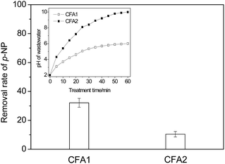
From Fig. 1 we can see that the removal rates of p-NP are different under the catalysis of CFA1 and CFA2. The CFA1 has better catalytic performance, with a p-NP removal rate of 32.1%, while it is only 10.4% for CFA2.
The variation in wastewater pH could be a primary reason for the difference. As shown in the inset of Fig. 1, the pH of p-NP wastewater changed continuously from 2 to 6 for CFA1 and from 2 to 10 for CFA2. It is well known that H2O2 is relatively stable in acidic conditions compared with the stability in alkali conditions, where H2O2 can decompose easily via eqn (4):
| 2H2O2 → 2H2O + O2 | (4) |
So, when the pH of the wastewater increases to 10 under the catalysis of CFA2, the utilization rate of H2O2 could be lower, i.e., more H2O2 could decompose ineffectually. In addition, the Fenton/Fenton-like process always shows a good performance in acidic conditions, which actually limits the use of CFA2 severely. CFA1 was chosen for the following work.
The difference could be due to the different modification mechanisms of the three modification methods. In acid modification, the acid can neutralize the alkali substance in/on CFA, generate a huge amount of grooves and pores, increase the specific surface area, and finally expose the active sites (such as Fe2O3 and Fe3O4). The above processes are beneficial to the catalytic capacity of the catalyst. Alkali modification could destroy the crystal structure of the silicate and the bond between Si and O, resulting in a change in the structure of CFA. However, the adsorption of alkali substance on the surface of CFA could increase the wastewater pH, which could have a severe negative effect on the treatment of organic wastewater. Although the alkali-modified CFA was washed using deionized water and the pH of the supernatant reached 7, this could not eliminate the alkaline substance thoroughly from the surface of the catalyst, which could therefore still hinder the catalytic reaction.
As for the heat modification, it is actually a process of dehydration which causes the structural readjustment and phase transition. The catalytic capacity is seriously affected by the variation in the physicochemical properties of CFA during heat modification. According to the above analysis and experimental results, acid modification was used in the following work.
3.2 Preparation of granular MCFA
The recycling of MCFA powder can be realized by precipitation and filtration methods. However, precipitation and filtration by gravity is obviously slow, and vacuum filtration can definitely consume extra power. In order to accelerate the separation and to decrease the loss of MCFA powder, transforming the MCFA powder into a granular form easily and cheaply is a promising path for application in industry.The effect of the mass ratio of the clay (5%, 10%, 20%, 30%, 50%) was studied first. Due to the poor plasticity of MCFA powder, it is difficult for MCFA powder to bond together with a low content of clay but the resulting product is easily broken when it is used. The granulation process and experimental phenomena are described in Table 1. In this work, 30% clay loading was chosen as the optimal value, due to its easy granulation process. For the higher mass ratio (50%), the catalytic performance of the catalyst decreased slightly (data not given), due to the reduction in the mass ratio of the catalyst.
| Proportion of bonding agent/% | 5 | 10 | 20 | 30 | 50 |
| Granulation process | Difficult | Difficult | Relatively easy | Easy | Easy |
| Experimental phenomenon | The granularity breaks after 3–4 min of wastewater treatment | The catalyst on the surface of granular MCFA falls off | The solution becomes muddy during the wastewater treatment | The solution remains clear during the wastewater treatment | The solution remains clear during the wastewater treatment |
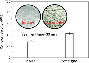
In addition, the catalytic performances of the two granular MCFAs produced by kaoline and attapulgite (30%) were compared and the results are given in Fig. 3. We can see from Fig. 3 that the granular MCFA prepared with attapulgite has a better catalytic performance (43.1% of p-NP removal rate) than that of the one prepared with kaoline (28.6% of p-NP removal rate). This result could be related to the special features of attapulgite: namely, its better bonding property, larger specific surface area, and stronger plasticity.
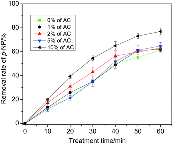 | ||
| Fig. 4 Effect of modifier of pore structure (activated carbon) on catalytic performance of granular MCFA. | ||
Actually, even if AC can improve the quality of the pore structure, it can occupy some of the surface area of granular MCFA, so it decreases the area of active sites that have catalytic capacity. This could be the reason for the lack of obvious change in p-NP removal rate. Additionally, although the removal rate of p-NP is 76.9% at 10% of AC, the plasticity of granular MCFA becomes poorer and it is easily broken. After consideration, modification of the pore structure is not recommended.
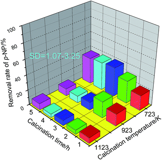
A pre-study showed that a temperature lower than 673 K is not appropriate for preparing granular MCFA with enough rigidity. Therefore, higher temperatures (723, 923, and 1123 K) were investigated herein. The adsorptive capacity of granular MCFA was used here to evaluate the effect of calcination temperature and time because the adsorptive capacity can indicate whether the pores have been broken and the specific surface area has been reduced. The results are given in Fig. 5. From Fig. 5 we can see that the granular MCFA calcined at 723 K has the best adsorptive capacity at any calcination time in the range 1–5 h. A higher temperature (≥923 K) could cause the collapse/closure of some pores, resulting in an obvious decrease in adsorptive performance of the catalyst. A calcination temperature = 723 K and a calcination time = 3 h were chosen as the optimum values.
3.3 Preparation of Fe2O3/granular MCFA
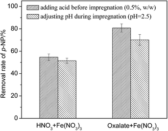
Common supports include, but are not limited to, Al2O3, activated carbon, and zeolite molecular sieves. Supporting Fe2O3 on the surface of granular MCFA can increase the number of active sites, while the initial Fe2O3 and Fe3O4 on the surface of granular MCFA can play their catalytic role simultaneously. However, supporting Fe2O3 on common supports only takes advantage of their property of adsorption. In addition, the cost of granular MCFA is lower than that of common supports. Thus, supporting Fe2O3 on the surface of granular MCFA could be a promising path for exploiting the advantage of granular MCFA.Nitric acid (an inorganic acid) and oxalic acid (an organic acid) were chosen to investigate the effect of the type of acid and the adjustment methods (adjusting pH during impregnation until pH = 2.5; adding acid before impregnation with the volume ratio of acid = 0.5%) are given in Fig. 6.
As shown in Fig. 6, we find that (I) the precursor solution adjusted by oxalic acid can produce a Fe2O3/MCFA catalyst with a relatively good catalytic performance; and (II) adding acid before impregnation is better than adjusting the pH during impregnation.
Oxalic acid can effectively prevent the hydrolysis of ferric ions by generating a stable Fe(III)-oxalate complex.20 Meanwhile, the oxalate ions and ferric ions can undergo competitive adsorption on the surface of granular MCFA, causing the even adsorption of ferric ions. Furthermore, oxalate can be converted to CO2 and H2O by a calcination process that can avoid the interference of anions (like NO3−).
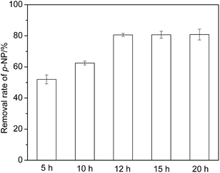
Fig. 7 shows that the p-NP removal rate increases obviously under the catalysis of Fe2O3/granular MCFA that was impregnated for 5–12 h, and then reaches a plateau (80.6%), even if the impregnation time is extended further. Thus, 12 h is considered to be an optimal impregnation time.
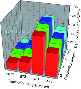
Fig. 8 shows that a calcination temperature lower or higher than 673 K is obviously disadvantageous to the catalytic performance of Fe2O3/granular MCFA. A lower calcination temperature (473 K) cannot stabilize Fe2O3 on the surface of granular MCFA. At a higher calcination temperature (≥873 K), the gas generated by the evaporation of the residual water in the catalyst and by the decomposition of oxalate did not spread normally to the surface of the catalyst, but spread rapidly. This could cause cracking of the granular MCFA, even affecting the diameter and distribution of the crystal grains and the strength of the combination of granular MCFA with the crystal, resulting in an easy loss of the active component into the wastewater.
Let us focus on a calcination temperature of 673 K. We can see that the calcination time has no obvious effect on the catalytic performance of Fe2O3/granular MCFA and 2 h is enough (80.8%). That is, oxalate can decompose and the Fe2O3 crystalline phase can form completely after a calcination time of 2 h.
3.4 Comparison of the physicochemical features of CFA, MCFA powder, granular MCFA and Fe2O3/granular MCFA
Acid modification and loading of Fe2O3 on the MCFA catalyst could change the physicochemical properties of CFA and MCFA (such as surface structure and chemical components). In order to understand their effects on the physicochemical properties of CFA and MCFA, a comparison of the measurements among CFA, MCFA powder, granular MCFA and Fe2O3/granular MCFA was conducted.| Specific surface area (m2 g−1) | Pore volume (μL g−1) | Pore diameter (nm) | |
|---|---|---|---|
| CFA | 19.2 | 63.1 | 1.45 |
| MCFA powder | 27.0 | 66.0 | 3.76 |
| Granular MCFA | 12.3 | 22.5 | 3.53 |
| Fe2O3/granular MCFA | 11.1 | 21.7 | 3.16 |
When we focus our attention on the granular MCFA, we can find in Table 2 that the granular MCFA has an obvious decrease in the specific surface area and pore volume compared with MCFA powder because of the bigger diameter of granular MCFA. A comparison of pore diameter between granular MCFA and MCFA powder represents the slight effect of bonding agent on this aspect.
Fe2O3/granular MCFA shows a further decrease in the three indices in Table 2. This is because of the loading of Fe2O3 on the surface of granular MCFA, which can block/cover the pores on the surface of granular MCFA. This can be observed intuitively from the SEM of Fe2O3/granular MCFA in Fig. 9, i.e., the structures on the surface of granular MCFA (Fig. 9A–C) disappear and some glossy particles emerge (the right-hand bigger picture in Fig. 9).
| SiO2 | Fe2O3 | Al2O3 | CaO | K2O | Na2O | MgO | LOIa | |
|---|---|---|---|---|---|---|---|---|
| a The loss on ignition analysis was carried out at 1073 K for 24 h. | ||||||||
| CFA | 66.10 | 5.45 | 16.30 | 5.48 | 1.24 | 0.60 | 1.03 | 3.48 |
| MCFA powder | 56.60 | 7.85 | 21.70 | 4.65 | 4.35 | 1.82 | 1.74 | 1.06 |
| Granular MCFA | 38.10 | 5.11 | 14.21 | 3.96 | 2.88 | 1.01 | 0.98 | 0.64 |
| Fe2O3/granular MCFA | 34.88 | 12.60 | 12.20 | 3.91 | 2.98 | 0.86 | 0.85 | 0.77 |
If we focus our attention on the CFA and MCFA powder first, variation in the proportions of Fe element, CaO, and LOI is the essence of acid modification. The acid modification obviously increases the proportion of Fe2O3 (from 5.45% to 7.85%), which is helpful in increasing the catalytic capacity of the MCFA powder because, until now, Fe is still the preferred metallic element that can catalyse the Fenton/Fenton-like process effectively.4,6,7 The LOI is the residue of organics that are not burned completely in the thermal power plant. The carbon particles that exist in the LOI have no catalytic capacity in the heterogeneous Fenton-like process but, instead, can occupy the working area, cover the surface of the active sites of MCFA powder and even decrease its catalytic capacity. The acid modification of CFA can decrease the proportion of LOI from 3.48% to 1.06%, which is welcomed in this study.
As mentioned previously, some studies1,8,12 show that an acidic reaction condition is favoured in Fenton/Fenton-like processes; a higher pH is adverse for the existence of H2O2 and the generation of ·OH. Thus, removing CaO from CFA is a necessary step since the dissolution of CaO in water can generate CaOH and cause a rapid increase in pH. As shown in Table 3, the proportion of CaO reduces to 4.65% (MCFA) from 5.48% (CFA), indicating that the acid modification removed a portion of the CaO.
If we shift attention to the granular MCFA and Fe2O3/granular MCFA, the proportions of chemical component decrease because of the addition of bonding agent. Specifically, the proportion of Fe2O3 in Fe2O3/granular MCFA increases to 12.60% from 5.11%; this can be explained easily by the loading of Fe2O3.
3.5 Catalytic performance and stability of MCFA catalysts in a Fenton-like process
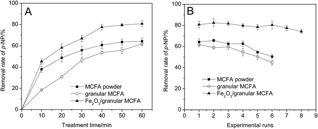
A comparison of the catalytic performances of three kinds of MCFA catalyst was carried out and is shown in Fig. 10. From Fig. 10A we can see that the MCFA powder and granular MCFA have similar catalytic performances for the treatment efficiency of p-NP wastewater. However, it is obvious that the MCFA powder can exhibit rapid catalytic capacity. The removal rate of p-NP in an MCFA powder catalysed Fenton-like process can approach its maximum value (60.7%) at 40 min, while 60 min (61.8%) is needed for the granular MCFA-catalysed process. Fe2O3/granular MCFA has the best performance and the removal rate of p-NP reaches 80.7% at 60 min.Besides investigating and comparing their catalytic performance, the stability of the three catalysts was studied. From Fig. 10B we can observe that the MCFA powder and granular MCFA have analogous stability, i.e., they can be used 4 times (MCFA powder) and 3 times (granular MCFA), with no obvious decay in catalytic capacity. After this, their catalytic capacity starts to decline. In contrast, Fe2O3/granular MCFA exhibits the best stability and catalytic capacity among the three catalysts; it can be used at least 6 times, while the removal rate of p-NP remains at no less than 80%. This is notably advantageous for reducing the amount of catalyst.
The difference in catalytic capacity and stability could be due to the different specific surface areas and different amounts of active sites on the surface of different catalysts. The bigger specific surface area of MCFA powder can result in a better adsorptive capacity and more rapid dissolution of iron element into the wastewater, whereas granular MCFA is weaker in these aspects (see Table 4). This could be the reason why the MCFA powder catalysed Fenton-like process has a more rapid p-NP removal rate than that of granular MCFA. Compared with these two catalysts, Fe2O3/granular MCFA undoubtedly has more active sites, so it can exhibit the best catalytic capacity among them.
| Experimental runs | 1 | 2 | 3 | 4 | 5 | 6 | 7 | 8 |
| MCFA powder/mg L−1 | 0.449 | 0.422 | 0.381 | 0.330 | 0.269 | 0.238 | — | — |
| Granular MCFA/mg L−1 | 0.218 | 0.201 | 0.195 | 0.191 | 0.185 | 0.171 | — | — |
| Fe2O3/granular MCFA/mg L−1 | 0.886 | 0.875 | 0.867 | 0.841 | 0.832 | 0.824 | 0.820 | 0.804 |
However, the leaching of Fe element into wastewater signifies a loss of active sites; this can be obtained from Table 4 which reveals that the Fe element always leaches from the surface of the catalyst. So the three kinds of MCFA catalyst cannot be used in an infinite loop; this experimental result accords with other studies.6,8,9
3.6 Treatment of secondary effluent
The studied heterogeneous Fenton-like process was tested in the treatment of a real secondary effluent. The COD of the effluent sample was approximately 136.5 mg L−1. After the treatment, the residual COD reduced to 48.4 mg L−1, 54.4 mg L−1 and 31.2 mg L−1 under the catalysis of MCFA powder, granular MCFA and Fe2O3/granular MCFA, respectively, revealing COD treatment rates of 64.5%, 60.1% and 77.1%.Additionally, the reusability of the catalyst was tested, revealing stable catalytic performances up to 3 times for MCFA powder and granular MCFA and 5 times for Fe2O3/granular MCFA (removal rate of COD ≥ 57%). The reusability capacity of the catalyst here is poorer than that shown in Fig. 10B. The complicated components in the secondary effluent could cause this as some components (besides the organics in the effluent) could react with/cover the active component on the surface of the catalyst, resulting in the rapid inactivation of the catalyst. On the whole, the prepared catalysts in this paper can treat wastewater (simulated and real wastewater) effectively, showing their elementary catalytic capacity and favourable application prospects.
3.7 Catalytic oxidation mechanism of MCFA in a Fenton-like process
The acid modification of CFA and the loading of Fe2O3 on the surface of granular MCFA actually have the same purpose, i.e., to increase the proportion of useful crystalline phase (maghemite (γ-Fe2O3) and hematite (α-Fe2O3)) and to decrease the proportion of amorphous phase (aluminium silicate). H2SO4 impregnation can obviously dissolve the amorphous phase into solution, leaving the crystalline phase and resulting in a porous structure. Loading Fe2O3 on the surface of granular MCFA is a method of rapidly and obviously increasing the proportion of Fe2O3.According to the above statement, the three catalysts have an identical catalytic process that can occur simultaneously on the surface of the catalyst and in the solution due to the dissolution of iron element. The detailed mechanism is proposed as eqn (5)–(10):
![[triple bond, length as m-dash]](https://www.rsc.org/images/entities/char_e002.gif) FeIII + H2O2 → FeIII + H2O2 → ![[triple bond, length as m-dash]](https://www.rsc.org/images/entities/char_e002.gif) Fe(HO2)2+ + H+ Fe(HO2)2+ + H+
| (5) |
![[triple bond, length as m-dash]](https://www.rsc.org/images/entities/char_e002.gif) Fe(HO2)2+ → Fe(HO2)2+ → ![[triple bond, length as m-dash]](https://www.rsc.org/images/entities/char_e002.gif) FeII + HO2˙/O2˙− FeII + HO2˙/O2˙−
| (6) |
![[triple bond, length as m-dash]](https://www.rsc.org/images/entities/char_e002.gif) FeII + H2O2 → FeII + H2O2 → ![[triple bond, length as m-dash]](https://www.rsc.org/images/entities/char_e002.gif) FeIII + ˙OH + OH− FeIII + ˙OH + OH−
| (7) |
| FeOH2+ + H2O2 → Fe(OH)(HO2)+ + H+ | (8) |
| Fe(OH)(HO2)+ → Fe2+ + HO2˙/O2˙ + OH− | (9) |
| Fe2+ + H2O2 → Fe3+ + OH− + ˙OH | (10) |
On the iron-bearing surface the ferric element (![[triple bond, length as m-dash]](https://www.rsc.org/images/entities/char_e002.gif) FeIII) can react with H2O2 to form an unstable
FeIII) can react with H2O2 to form an unstable ![[triple bond, length as m-dash]](https://www.rsc.org/images/entities/char_e002.gif) Fe(HO2)2+ complex (eqn (5)). The decomposition of
Fe(HO2)2+ complex (eqn (5)). The decomposition of ![[triple bond, length as m-dash]](https://www.rsc.org/images/entities/char_e002.gif) Fe(HO2)2+ provides the catalyst (
Fe(HO2)2+ provides the catalyst (![[triple bond, length as m-dash]](https://www.rsc.org/images/entities/char_e002.gif) FeII, eqn (6)) for the heterogeneous Fenton-like process (eqn (7)).21,22 In the liquid phase, this is analogous to the Fe3+-catalysed homogeneous Fenton-like process. The Fe3+ always exists in the form of FeOH2+, which can be transformed to Fe2+ by reacting with H2O2 (see eqn (8) and (9)). The generated Fe2+ can play the critical role of a catalyst in the Fenton process (eqn (10)).23
FeII, eqn (6)) for the heterogeneous Fenton-like process (eqn (7)).21,22 In the liquid phase, this is analogous to the Fe3+-catalysed homogeneous Fenton-like process. The Fe3+ always exists in the form of FeOH2+, which can be transformed to Fe2+ by reacting with H2O2 (see eqn (8) and (9)). The generated Fe2+ can play the critical role of a catalyst in the Fenton process (eqn (10)).23
The organics can be directly oxidized by the ·OH in the solution or adsorbed on the surface of catalyst first and then oxidized. The degradation path and products of p-NP were determined in our previous paper.24 The highest p-NP removal rate in the Fe2O3/MCFA catalysed Fenton-like process is due to the greater number of active sites on the surface of Fe2O3/granular MCFA.
The catalytic performance of other metals, such as Mn, Cr, Ni, Cu, Zn, Bi, has been studied in other work.25–28 However, the co-catalytic action among them (including Fe) has not been widely studied. This could be a useful and promising study.
4. Conclusions
Different CFAs have different initial catalytic performances, due to the dissolution of alkali substance on the surface of CFA. Acid modification can activate the catalytic capacity of CFA more effectively (64.3% of p-NP removal rate) than alkali or heat modification (<45%). For the preparation of granular MCFA, attapulgite can bond MCFA powder together with a better performance (43.1% of removal rate of p-NP at 30 min) than kaoline (28.6% at 30 min), and a calcination temperature of 723 K is the optimal value for strengthening the rigidity of granular MCFA. Supporting Fe2O3 on granular MCFA can promote the catalytic performance significantly. Adjusting the pH of the precursor using oxalate before impregnation is recommended to produce Fe2O3/granular MCFA in this study, and the optimal impregnation time is 12 h. Calcining the impregnated granular MCFA at 673 K for 2 h is appropriate to obtain a satisfactory Fe2O3 crystalline phase. The three MCFA catalysts can be reused at least 3 times with 57% of COD removal rate even in treating real secondary effluents and they have an identical catalytic mechanism: namely, hydroxyl radicals (·OH) can be generated on the surface of the catalyst by a crystalline phase-catalyzed Fenton-like process and in solution by a homogeneous Fenton-like process. The organics in wastewater can be degraded on the surface of the catalyst and in the solution simultaneously.Conflicts of interest
There are no conflicts to declare.Notes and references
- J. J. Pignatello, E. Oliveros and A. Mackay, Crit. Rev. Environ. Sci. Technol., 2006, 36, 1–84 CrossRef CAS.
- N. Flores, I. Sirés, J. A. Garrido, F. Centellas, R. M. Rodríguez, P. L. Cabot and E. Brillas, J. Hazard. Mater., 2016, 319, 3–12 CrossRef CAS PubMed.
- M. R. Carrasco-Díaz, E. Castillejos-López, A. Cerpa-Naranjo and M. L. Rojas-Cervantes, Chem. Eng. J., 2016, 304, 408–418 CrossRef.
- Y. W. Pan, M. H. Zhou, X. Li, L. T. Xu, Z. X. Tang and M. M. Liu, Purif. Technol., 2016, 169, 83–92 CrossRef CAS.
- S. Garcia-Segura, L. M. Bellotindos, Y. H. Huang, E. Brillas and M. C. Lu, J. Taiwan Inst. Chem. Eng., 2016, 67, 211–225 CrossRef CAS.
- C. Khatri and A. Rani, Fuel, 2008, 87, 2886–2892 CrossRef CAS.
- H. F. Zhuang, H. J. Han and S. D. Shan, Fuel, 2016, 178, 155–162 CrossRef CAS.
- S. H. Chen and D. Y. Du, J. Cent. South Univ., 2014, 21, 1448–1452 CrossRef CAS.
- D. S. Duc, Asian J. Chem., 2013, 25, 4083–4086 CAS.
- M. Visa and A. Duta, J. Hazard. Mater., 2013, 244–245, 773–779 CrossRef CAS PubMed.
- T. Hai, Res. J. Chem. Environ., 2012, 16, 57–61 CAS.
- A. L. Zhang, N. N. Wang, J. T. Zhou, P. Jiang and G. F. Liu, J. Hazard. Mater., 2012, 201–202, 68–73 CrossRef CAS PubMed.
- M. Martin-Hernandez, J. Carrera, J. Perez and M. E. Suarez-Ojeda, Water Res., 2009, 43, 3871–3883 CrossRef CAS PubMed.
- C. J. An, S. Q. Yang, G. H. Huang, S. Zhao, P. Zhang and Y. Yao, Fuel, 2016, 165, 264–271 CrossRef CAS.
- N. Koshy and D. N. Singh, J. Mater. Civ. Eng., 2016, 28, 1–7 CrossRef.
- K. H. Zhang, D. X. Zhang and K. Zhang, Water Sci. Technol., 2016, 73, 1954–1962 CrossRef CAS PubMed.
- N. Chen, G. D. Fang, D. M. Zhou and J. Gao, Chemosphere, 2016, 165, 52–58 CrossRef CAS PubMed.
- X. Y. Li, D. Y. Zhang, X. Q. Liu, L. Y. Shi and L. B. Sun, Chem. Eng. J., 2016, 141, 184–194 CrossRef CAS.
- M. Juhyuk, D. K. Paul, M. Laurence and A. N. Paul, Cem. Concr. Compos., 2016, 67, 20–29 CrossRef.
- A. S. Petrick, B. Mauro, M. A. G. U. S. Selene, A. R. B. Souza and J. P. V. Vitor, J. Environ. Manage., 2015, 152, 120–131 CrossRef PubMed.
- R. G. Flores, S. L. F. Andersen, L. K. K. Maia and H. J. José, J. Environ. Manage., 2012, 111, 53–60 CrossRef CAS PubMed.
- X. F. Xue, K. Hanna and N. S. Deng, J. Hazard. Mater., 2009, 166, 407–414 CrossRef CAS PubMed.
- J. D. Laat and H. Gallard, Environ. Sci. Technol., 1999, 33, 2726–2732 CrossRef.
- N. N. Wang, Q. Zhao and A. L. Zhang, RSC Adv., 2017, 7, 27619–27628 RSC.
- C. M. van Genuchten and J. Pena, Environ. Sci. Technol., 2017, 51, 2982–2991 CrossRef CAS PubMed.
- S. Jauhar and S. Singhal, Ceram. Int., 2014, 40, 11845–11855 CrossRef CAS.
- X. M. Li, Y. Kong, S. J. Zhou and B. B. Wang, J. Mater. Sci., 2017, 52, 1432–1445 CrossRef CAS.
- S. Li, G. S. Zhang, H. Zheng, N. N. Wang, P. Wang and Y. Zheng, RSC Adv., 2016, 6, 82439–82446 RSC.
| This journal is © The Royal Society of Chemistry 2017 |

