 Open Access Article
Formation mechanism of thermally expandable microspheres of PMMA encapsulating NaHCO3 and ethanol via thermally induced phase separation
Shuqian Zhou,
Zhengfa Zhou*,
ChenRan Ji,
Weibing Xu *,
Haihong Ma,
Fengmei Ren and
Xuefan Wang
School of Chemistry and Chemical Engineering, Hefei University of Technology, Hefei, 230009, The People's Republic of China. E-mail: weibingxu@hfut.edu.cn; zhengfazhou@hfut.edu.cn; Tel: +86-0551-62901455
First published on 30th October 2017
Abstract
Thermally expandable microspheres (TEMs), employing PMMA as the shell and NaHCO3/ethanol as the core, were prepared via thermally induced phase separation (TIPS). The addition of NaHCO3 improves the foaming properties of the TEMs. A mechanism for TEMs formation was proposed, comprising the following steps: (1) the separation of homogeneous polymer solutions into polymer-rich and polymer-poor phases upon cooling, where decreases in both interfacial tension and interfacial free energy (ΔG) facilitate sphere formation in a polymer-rich phase located in the polymer-poor phase; (2) the deposition of PMMA and shell formation at the interface, aided by the acute contact angle (θ) and positive spreading coefficient (S); (3) the constant deposition of PMMA shells from both the polymer-rich phase and polymer-poor phase upon cooling; and (4) the detachment of TEMs from each other facilitated by shear force from stirring. This mechanism was supported by calculations, and the effects of quench rates and stirring speeds.
1 Introduction
Thermally expandable microspheres (TEMs), commonly used as blowing agents or lightweight materials, are usually prepared via suspension polymerization.1 TEMs contain core–shell structures, and thermoplastic polymers (e.g., poly(acrylonitrile), poly(methyl methacrylate) and poly(vinylidene chloride)) serve as shell materials. Meanwhile, organic compounds with low boiling points, such as i-butane, n-hexane and petroleum ether, are employed as blowing agents.2,3Thermally induced phase separation (TIPS) is a widely used technique that can be used to prepare scaffolds for tissue engineering purposes4,5 and porous membranes.6 TIPS involves cooling a homogeneous polymer solution to a temperature where the single-phase system becomes thermodynamically unstable and spontaneously separates into a polymer-rich phase and a polymer-poor phase.7 Wu et al.8 prepared PVDF/PAN blend porous membranes via TIPS, which can be used as separators in lithium ion batteries. Moreover, Önder and coworkers9 have fabricated rigid poly(lactic acid) foams via TIPS.
The mechanism involved in TIPS technology has been investigated. Witte et al.10 and Boomgaard et al.11 demonstrated that a spinodal phase diagram could explain the mechanism. They concluded that liquid–liquid separation begins in the demixing gap to form porous structures. Meanwhile, the liquid–liquid demixing gap is subdivided into a region of spinodal demixing that is bounded by the spinodal. Then two regions of nucleation and growth between the binodal and the spinodal are formed. Nishi et al.12 studied the TIPS mechanism for polystyrene-poly(vinyl-methyl ether) mixtures using light transmission, optical microscope and pulsed NMR studies. These efforts revealed that phase separation occurred either via a spinodal mechanism or via a nucleation and growth mechanism. Tompa13 and Altena et al.14 calculated phase diagrams for ternary systems of amorphous polymers using binary interaction parameters, where the results supported a nucleation and growth mechanism. Mannella et al.15 investigated the TIPS behavior of a poly(L-lactide)-dioxane–water system directly by means of cloud point detection via light transmittance measurements, and indirectly through the preparation of several porous foams. Considerable pore dimension variation was noted with variations in holding time, holding temperature and poly(L-lactide) concentration; the results also supported a nucleation and growth mechanism.
Ogawa et al.16 prepared poly(methyl methacrylate) foamable particles via TIPS from a PMMA/ethanol mixture. Unfortunately, the foamable particles possessed poor foaming properties, being only twice the size of the original particles even under vacuum foaming conditions.
In this work, TEMs with PMMA as the shell and NaHCO3/ethanol solution as the core were prepared via the simple method of TIPS. The addition of NaHCO3 improved the TEMs foaming properties. The mechanism for TIPS-based TEMs formation was probed via the following methods: (1) measuring the contact angle (θ) and tension (γgl) at different temperatures; (2) calculating the interfacial free energy (ΔG) and spreading coefficient (S) with changing temperature; and (3) investigating the effects of quenching rate and stirring speed on the morphologies of the TEMs. To the best of our knowledge, there are few reports investigating the formation mechanism of TEMs via TIPS.
2 Experimental
2.1 Materials
Reagent grade NaHCO3, ethanol, and PMMA (Mw = 5.05 × 10⁴, Mw/Mn = 1.15) were all obtained from Sinopharm, China. All chemicals were used as received without further purification.2.2 Thermally induced phase separation experiments
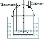
50 g of ethanol, 3 g of NaHCO3 and 0.5 g of PMMA were added to a 100 mL glass vessel, which was equipped with an agitator, a condenser (Allihn type), and a thermometer. A schematic diagram of the apparatus is shown in Fig. 1. The entire apparatus was submerged in a 60 °C water bath. The mixture was stirred at 100 rpm for 1 h, and a homogeneous solution was obtained. Then the apparatus was quickly transferred to an ice-water bath, where it was cooled to 5 °C with different quenching times or stirring speeds. The quenching time was set at 2 min, 10 min, 30 min, or 60 min with a stirring speed of 200 rpm; or the stirring speed was set at 0 rpm, 100 rpm, 200 rpm, 300 rpm, 400 rpm, or 500 rpm with a quenching time of 2 min. The mixture had a slightly opaque color. The mixture was filtered under vacuum filtration with a membrane filter size of 0.1 μm. TEMs were obtained after washing successively with distilled water and ethanol, and drying in an oven at 30 °C for 2 h.2.3 Characterization
Scanning electron microscope (SEM) images of the TEMs were collected on a scanning electron microscope (SU8020, Shimadzu, Japan); samples for SEM imaging were deposited on Cu wafers. Each sample was sputter-coated with a thin layer of gold to prevent sample-charging problems.The contact angle (θ) was determined using contact angle measurements (DSA100, Kruss, Germany). Ethanol/NaHCO3 solution and PMMA were put into beakers with closed lids. The temperature was set at 5 °C, 10 °C, 19 °C, 31 °C, 40 °C, 49 °C, or 58 °C.
The surface tension was analyzed using a surface tensiometer (BYZ-1, Hengping, China). The samples of ethanol/NaHCO3 solution were the same as those used for contact angle measurements.
The particle size distribution was measured using a laser scattering particle size analyzer (LS, MS-2000, Malvern). TEMs were dispersed in deionized water under ultrasonic dispersion for 5 min.
The encapsulated ethanol and NaHCO3 content were investigated using a thermal gravimetric analyser (TGA, NETZSCH, 209F3). The samples were heated from 30 °C to 900 °C at a rate of 2 °C min−1 under a nitrogen atmosphere.
3 Results and discussion
3.1 Formation mechanism of TEMs via TIPS
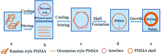
0.5 g of PMMA and 3 g of NaHCO3 were dissolved in 50 g of ethanol at 60 °C, and a uniform phase solution was obtained (Fig. 2(a)). The uniform phase separated into a polymer-poor phase and a polymer-rich phase when the temperature was reduced,9 and an interface formed between the polymer-poor phase (outer) and the polymer-rich phase (inner). In the PMMA/NaHCO3/ethanol mixture a demixing polymer mechanism supported a spinodal one, which contains a polymer-rich phase, a polymer-poor phase and the interface. Meanwhile, the PMMA chains might transform from a random style to an oriented style under the shear force from stirring (Fig. 2(b) and (c)).Next, PMMA deposition is initiated firstly in the polymer-rich phase where PMMA forms a shell at the interface between the polymer-poor phase and polymer-rich phase. The evidence for the aforementioned mechanism is as follows. (1) The interfacial tension generated between the polymer-poor phase and polymer-rich phase causes the polymer-rich phase to form droplets.17 In addition, the interfacial free energy decreases with cooling, and the decrease in interfacial free energy also facilitates the polymer-rich phase forming spheres within the polymer-poor phase. (2) Vold17 found that a liquid could form a concave interface and a solid could be spontaneously wetted on the liquid surface when the contact angle was less than 90°. Since the contact angle of the ethanol/NaHCO3 solution on the PMMA surface was less than 90°, the ethanol/NaHCO3 solution could form a concave interface and PMMA had the tendency to deposit on the ethanol/NaHCO3 solution surface. (3) Good and Fowkes17 proposed that a spreading coefficient greater than zero facilitates a shell material encapsulating a core material. The experimental results indicated the spreading coefficient between the polymer-rich phase and the polymer-poor phase was positive. The ethanol/NaHCO3 solution could thus be encapsulated by PMMA. (4) Mannella et al.15 prepared a poly-L-lactide porous membrane via TIPS. In this work, it was postulated that the microspheres might have physical contact with each other. The formation of TEMs was deemed unfeasible without stirring. The effect of shear forces from stirring might orient the PMMA chains and facilitate the formation of TEMs,18,19 and also keep microspheres separate from each other. Therefore, PMMA formed the shells and ethanol/NaHCO3 solution formed the core materials upon cooling and stirring (Fig. 2(d)).
Thereafter, the shell grew as PMMA was deposited constantly from the polymer-rich phase and polymer-poor phase due to further decreases in temperature, and disjointed microspheres were obtained upon stirring (Fig. 2(e)). As a result, TEMs were obtained. A schematic representation of the mechanism is shown in Fig. 2.
3.2 Shell-formation
The interfacial free energy between the PMMA and NaHCO3/ethanol solutions is related to the temperature according to the Gibbs free energy.20 Harkins defined the spreading coefficient as the reduction in interfacial free energy per unit area.17 Vold proposed that interfacial free energy, interfacial tension, and the spreading coefficient could be described as shown in eqn (1).17| ΔG = −S = γgs − γg1 − γ1s | (1) |
According to the Young equation, the relation between γgs, γls and γgl can be described as shown in eqn (2).21
γgs = γ1s + γg1![[thin space (1/6-em)]](https://www.rsc.org/images/entities/char_2009.gif) cos cos![[thin space (1/6-em)]](https://www.rsc.org/images/entities/char_2009.gif) θ θ
| (2) |
Eqn (3) can be obtained through combining eqn (1) and (2).
ΔG = −S = −γg1(cos![[thin space (1/6-em)]](https://www.rsc.org/images/entities/char_2009.gif) θ − 1) θ − 1)
| (3) |
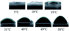 | ||
| Fig. 3 Shapes of the contact angles between ethanol/NaHCO3 solution and a PMMA surface under a balanced state at different temperatures. | ||
| Temperature (°C) | θ (°) | γgl (mN m−1) | ΔG (J mol−1) | S | ||||||||
|---|---|---|---|---|---|---|---|---|---|---|---|---|
| 1 | 2 | 3 | Average | SD | 1 | 2 | 3 | Average | SD | |||
| 5 | 5.58 | 5.63 | 5.62 | 5.61 | 0.022 | 23.7 | 23.8 | 23.8 | 23.8 | 0.057 | −0.12 | 0.12 |
| 10 | 6.31 | 6.33 | 6.29 | 6.31 | 0.017 | 23.4 | 23.7 | 23.6 | 23.6 | 0.22 | −0.15 | 0.15 |
| 19 | 8.18 | 8.23 | 8.22 | 8.21 | 0.037 | 23.5 | 23.7 | 23.1 | 23.4 | 0.25 | −0.3 | 0.3 |
| 31 | 9.25 | 9.25 | 9.22 | 9.24 | 0.012 | 22.5 | 22.8 | 22.8 | 22.7 | 0.14 | −0.41 | 0.41 |
| 40 | 10.91 | 10.93 | 10.94 | 10.93 | 0.013 | 22.2 | 22.4 | 22.4 | 22.4 | 0.12 | −0.42 | 0.42 |
| 49 | 17.25 | 17.29 | 17.27 | 17.27 | 0.016 | 21.8 | 21.9 | 21.5 | 21.7 | 0.17 | −0.98 | 0.98 |
| 58 | 25.14 | 25.13 | 25.09 | 25.12 | 0.022 | 21.4 | 21.6 | 21.6 | 21.5 | 0.10 | −2.04 | 2.04 |
The tension between gas and liquid (γgl) was determined using a surface tensiometer. Values of γgl were determined at 5 °C, 10 °C, 19 °C, 31 °C, 40 °C, 49 °C, and 58 °C. The results indicated that γgl increased with decreasing temperature (Table 1).
The values of ΔG and S were obtained using eqn (3) (Table 1). The interfacial free energy decreased when the temperature was reduced from 58 °C to 5 °C, providing the conditions for the polymer-rich phase to form spheres among the polymer-poor phase. S decreased with decreasing temperature and remained positive during the process of TIPS. Based on the theory of Good and Fowkes,17 there existed a tendency for the ethanol/NaHCO3 solution to be encapsulated by PMMA when the spreading coefficient was positive.
On the basis of the calculation results, we concluded that PMMA could form a shell at the interface between the polymer-rich phase and polymer-poor phase while ethanol/NaHCO3 solution could be encapsulated by PMMA. Microspheres with a core–shell structure were formed.
3.3 Effects of quench rate and quench time
The mixture of ethanol/NaHCO3 and PMMA was quenched from 60 °C to 5 °C within 2 min, 10 min, 30 min or 60 min, under a stirring speed of 200 rpm. The TEMs obtained were characterized using SEM (images shown in Fig. 4). The TEMs were fully spherical when the quenching time was 2 min (Fig. 4(a)) or 10 min (Fig. 4(b)). However, when the quenching time was greater than 30 min, some PMMA formed complete spheres while some formed hemispheres (Fig. 4(c)). The proportion of hemispheres increased with an increase in quench times (Fig. 4(d)). Meanwhile, the percentages and diameters of the microspheres were influenced by the quench rate. A reasonable explanation was that a high quenching rate led to a lower amount of PMMA diffusing from the polymer-rich phase to the polymer-poor phase. Consequently, PMMA could quickly deposit at the interface between the polymer-rich phase and the polymer-poor phase. However, a slow quenching rate allowed enough time for PMMA to diffuse from the polymer-rich phase to the polymer-poor phase; the small concentration difference led to much worse interfacial stability. Therefore, the core–shell structure of some spheres was incomplete. The experimental results also provided evidence for the suggested mechanism.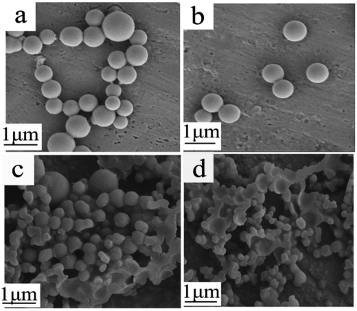 | ||
| Fig. 4 SEM images of TEMs prepared with different quench times: (a) 2 min; (b) 10 min; (c) 30 min; and (d) 60 min. | ||
Samples were extracted from the experimental apparatus at 60 °C, 28 °C, 10 °C and 5 °C during the quenching of the mixture of ethanol/NaHCO3 and PMMA from 60 °C to 5 °C under a stirring speed of 200 rpm. We found that the mixture began to muddy at about 28 °C in many experiments, therefore 28 °C was the cloud point of the mixture of ethanol/NaHCO3 and PMMA, and 28 °C was selected as one of the temperature points. The samples were put into glass bottles which had been previously set to 60 °C, 28 °C, 10 °C or 5 °C, depending on the respective sample. A photo of the bottle was taken within 10 s, and the results are shown in Fig. 5. The mixture was transparent when the temperature was above 28 °C (Fig. 5(I)), and became muddy immediately at about 28 °C (Fig. 5(II)). The mixture turbidity increased as the temperature decreased (Fig. 5(III) and (IV)), which might be due to an increase in the amount and diameter of the TEMs.
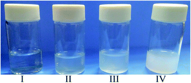 | ||
| Fig. 5 Photos of mixtures of ethanol/NaHCO3 and PMMA at different temperature points during quenching: (I) 60 °C; (II) 28 °C; (III) 10 °C; and IV: 5 °C. | ||
Other samples were also extracted from the experimental apparatus at 60 °C, 28 °C, 10 °C and 5 °C, respectively, and filtrated within 10 s. No filtrate was obtained at 60 °C. The filtrate of each sample was dried in a drying oven at 30 °C, and then it was fixed with epoxy resin and cut into slices with a wallpaper knife to observe the thickness of the PMMA shell via SEM. The results are shown in Fig. 6. The thickness of the PMMA shell gradually increases as the temperature decreases during quenching.
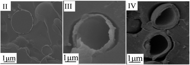 | ||
| Fig. 6 SEM images of TEMs at different temperature point during quenching: (II) 28 °C; (III) 10 °C; and (IV): 5 °C. | ||
3.4 Effects of stirring
The polymer chains could straighten and orientate into molecular bundles.18 Diat et al.19 investigated the effects of shear force on the orientation of lyotropic lamellar polymer molecules. They found that the kinetic instability of the fluid under the shear forces of stirring led the polymer to transform into multilayer vesicles; a single vesicle was eventually formed with increasing shear force and time. As a result, the shear force facilitated core–shell structure formation. The effects of stirring observed in our work might be the same as for lyotropic lamellar polymers. The shear force oriented the PMMA chains and facilitated TEMs formation; it also prevented microspheres from contacting each other.The morphologies of TEMs quenched from 60 °C to 5 °C within 2 min at different stirring speeds are shown in Fig. 7. In this work, the ethanol/NaHCO3 and PMMA mixture also formed a porous membrane without stirring (Fig. 7(A)). When the stirring speed was below 400 rpm, the ethanol/NaHCO3 and PMMA mixture formed TEMs. The average diameter of the TEMs decreased upon increasing the stirring speed (Fig. 7(B)–(E)). TEMs were not fully spherical when the stirring speed was 500 rpm (Fig. 7(F)), and too large a shear force from stirring affected the integrity of the TEMs. Based on these results, it could be concluded that the effects of stirring might orient the PMMA chains and facilitate TEMs formation, and make TEMs disconnect from each other.
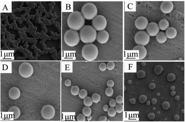 | ||
| Fig. 7 SEM images of TEMs prepared at different stirring speeds: (A) 0 rpm; (B) 100 rpm; (C) 200 rpm; (D) 300 rpm; (E) 400 rpm; and (F) 500 rpm. | ||
The size distribution of TEMs prepared at different stirring speeds is shown in Fig. 8. The average diameters of TEMs with stirring speeds of 100 rpm, 200 rpm, 300 rpm, and 400 rpm are 4.3 μm, 3.1 μm, 2.5 μm and 2.1 μm, respectively. Jonsson22 and Kim et al.3 found that the diameter of TEMs prepared via suspension polymerization decreased upon increasing the stirring speed. In this work, the diameters of TEMs from TIPS were also found to inversely correlate with stirring speed. Namely, TEMs with different diameters could be obtained by controlling the stirring speed; this means the cell size of foaming materials could be easily adjusted for various applications.
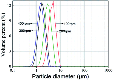 | ||
| Fig. 8 Particle size distribution of TEMs prepared at different stirring speeds. Quench rate: quenching from 60 °C to 5 °C within 2 min; stirring speed: 100 rpm, 200 rpm, 300 rpm, or 400 rpm. | ||
3.5 Core-shell structure and foaming properties
The core–shell structure and foaming properties of typical TEMs, which were prepared by quenching from 60 °C to 5 °C within 2 min under stirring at 200 rpm, were investigated. To verify the core–shell structure of the TEMs, the TEMs were fixed with epoxy resin and cut into slices. Fig. 9 shows an image of the cross section of the TEMs; it clearly shows that TEMs present a hollow inner and outer shell structure.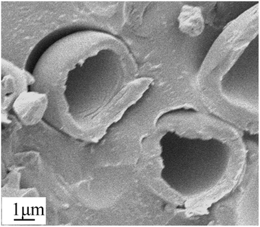 | ||
| Fig. 9 SEM image of a cross section of TEMs prepared at 200 rpm upon quenching from 60 °C to 5 °C within 2 min. | ||
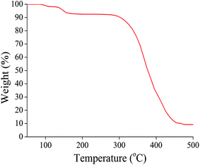
The ethanol and NaHCO3 content was analyzed via TG analysis (Fig. 10). The weight loss of ethanol over the range from 102 °C to 115 °C in the first step was about 2.2%. The weight loss of CO2 upon NaHCO3 decomposition over the range from 115 °C to 165 °C in the second step was 5.1%. The PMMA shell decomposed at about 320 °C. The residue coming from NaHCO3 was about 6.3%. Therefore the calculated encapsulated ethanol and NaHCO3 content was 2.2% and 11.4%, respectively.
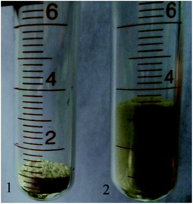
The TEMs were heated to 120 °C in an oven for 30 min to investigate the foaming properties. Digital photographs of unexpanded and expanded TEMs are shown in Fig. 11. The TEMs were calibrated at 1 cm before foaming (Fig. 11(1)). The maximum expansion volume of the TEMs was about 3.5 times the original volume under ambient pressure (Fig. 11(2)).
4 Conclusions
A PMMA and ethanol/NaHCO3 homogeneous solution separated into a polymer-rich phase and a polymer-poor phase upon decreasing the temperature, and an interface formed. First, the interfacial tension and a reduction in interfacial free energy led the polymer-rich phase to form spheres among the polymer-poor phase. Second, since the contact angle between the ethanol/NaHCO3 solution and the PMMA surface was less than 90°, the ethanol/NaHCO3 solution could form a concave interface where PMMA could deposit. Third, as the spreading coefficient between the polymer-rich phase and polymer-poor phase was positive, PMMA could encapsulate the ethanol/NaHCO3 solution. Finally, the shear force from stirring facilitated TEMs formation while separating TEMs from each other. Therefore, PMMA could form a shell, and the shell grew as the temperature decreased further due to a decrease in the solubility of PMMA. A higher quench rate suppressed the diffusion of PMMA from the polymer-rich to the polymer-poor layer. As a result, PMMA could quickly deposit and fix at the interface. TEMs with different diameters could be obtained by controlling the stirring speed. Based on the calculation results, and the effects of quench rate and stirring speeds on the morphologies of the TEMs, the proposed formation mechanism for TEMs via TIPS was reasonable.Conflicts of interest
There are no conflicts to declare.Acknowledgements
The authors are grateful for financial support from the Fundamental Research Funds for the Central Universities (JD2016JGPY002 and JZ2017YYPY0241).References
- J. R. Mi, H. Jung, J. U. Ha, S. H. Baeck and E. S. Sang, Colloid Polym. Sci., 2017, 29, 171–180 Search PubMed.
- M. Safajou-Jahankhanemlou, F. Abbasi and M. Salami-Kalajahi, Colloid Polym. Sci., 2016, 294, 1–10 Search PubMed.
- J. G. Kim, U. H. Jin, K. J. Sun, K. Lee and S. H. Baeck, Colloid Polym. Sci., 2015, 293, 3595–3602 CAS.
- F. A. Jahwari, A. A. W. Anwer and H. E. Naguib, J. Polym. Sci., Part B: Polym. Phys., 2015, 53, 795–803 CrossRef.
- Z. Q. Guo, C. Yang, Z. P. Zhou, S. Chen and F. Li, RSC Adv., 2017, 54, 34063–34070 RSC.
- C. Zeiger, J. Kumberg, F. Vullers, M. Worgull, H. Holscher and M. N. Kavalenka, RSC Adv., 2017, 52, 32806–32811 RSC.
- J. T. Fu and J. M. Torkelson, Macromolecules, 1990, 23, 4983–4989 CrossRef.
- Q. Y. Wu, H. Q. Liang, L. Gu, Y. Yu, Y. Q. Huang and Z. K. Xu, Polymer, 2016, 107, 54–60 CrossRef CAS.
- Ö. C. Önder, E. Yilgör and I. Yilgör, Polymer, 2016, 107, 240–248 CrossRef.
- P. V. D. Witte, P. J. Dijkstra, J. W. A. V. D. Berg and J. Feijen, J. Membr. Sci., 2017, 117, 1–31 CrossRef.
- (a) T. V. D. Boomgaard, R. M. Boom and C. A. Smolders, Macromol. Symp., 1990, 39, 271–281 CrossRef; (b) R. M. Boom, H. W. Reinders, H. H. W. Rolevink, T. V. D. Boomgaard and C. A. Smolders, Macromolecules, 1994, 27, 2041–2044 CrossRef CAS.
- T. Nishi, T. T. Wang and T. K. Kwei, Macromolecules, 1975, 8, 17–21 Search PubMed.
- H. Tompa, Polymer solutions, Butterworths, London, 1956, p. 82 Search PubMed.
- F. W. Altena and C. A. Smolders, Macromolecules, 1982, 15, 1491–1497 CrossRef CAS.
- G. A. Mannella, F. C. Pavia, G. Conoscenti, V. L. Carrubba and V. Brucato, J. Polym. Sci., Part B: Polym. Phys., 2014, 52, 979–983 CrossRef CAS.
- H. Ogawa, A. Ito, K. Taki and M. Ohshima, J. Appl. Polym. Sci., 2010, 106, 2825–2830 CrossRef.
- R. D. Vold and M. J. Vold, Colloid and interface chemistry, Addison-Wesley, 1983 Search PubMed.
- G. Strobl, The physics of polymers, Springer Verlag, Berlin, 2012 Search PubMed.
- O. Diat and D. Roux, J. Phys. II, 1993, 3, 9–14 CrossRef CAS.
- G. Strobl, The physics of polymers, Springer Verlag, Berlin, 2012 Search PubMed.
- E. Charles and J. Carraher, Polymer Chemistry, Florida, CRC press, 8th edn, 2010 Search PubMed.
- M. Jonsson, O. Nordin, E. Malmström and C. Hammer, Polymer, 2006, 47, 3315–3324 CrossRef CAS.
| This journal is © The Royal Society of Chemistry 2017 |

