 Open Access Article
Creative Commons Attribution 3.0 Unported Licence
Magnetic N-containing carbon spheres derived from sustainable chitin for the selective oxidation of C–H bonds†
Yunrui Zhangab,
Haihong Niuab,
Xiangjie Zhangab,
Junxiu Panab,
Yang Dongab,
Haijun Wangab and
Yongjun Gao *ab
*ab
aKey Laboratory of Chemical Biology of Hebei Province, College of Chemistry and Environmental Science, Hebei University, Baoding 071002, China. E-mail: yjgao@hbu.edu.cn
bKey Laboratory of Medicinal Chemistry and Molecular Diagnosis of Ministry of Education, College of Chemistry and Environmental Science, Hebei University, Baoding 071002, China
First published on 8th November 2017
Abstract
A kind of magnetic N-containing carbon material was synthesized by a simple method using sustainable N-acetyl-D-glucosamine (NAG) and iron nitrate as the raw materials. In C–H oxidation reactions such as the epoxidation of stilbene and styrene, and the oxidation of ethylbenzene, the carbon catalyst exhibited excellent catalytic activity and selectivity for the target products. The superparamagnetic properties at room temperature facilitated catalyst recycling and reusability when it was used as a catalyst. The relationship between the catalytic results and the N 1s XPS analysis indicated that the graphitic N species located in the carbon skeleton was the key accelerating factor which promoted the catalytic C–H oxidation. Density functional theory (DFT) calculations further indicated that the iron species were not an essential factor but they acted as promoters for the catalytic performance of the catalyst. This study will expand the application of biomass-based heteroatom-containing compounds.
Introduction
The catalytic oxidation of C–H bonds has received significant attention as it is an efficient measure to transform low-cost alkanes or alkenes to valuable oxygen-containing chemicals.1 So far, a series of homogeneous and heterogeneous transition metal-based catalytic systems have been developed for this procedure.2 However, many of these transition metals are precious metals, which would increase product costs. More importantly, many metals used in the oxidation of organic substances are toxic and strictly restricted in some fields such as pharmaceutical production.3,4 In addition, a homogeneous catalyst is difficult to separate from the catalytic system. Therefore, it is significant to develop a nontoxic and heterogeneous catalytic system for the oxidation of C–H bonds in organic substances.Carbon nanomaterials have been developed as a kind of transition metal-free catalyst for some traditional reactions in recent years, such as oxidation, dehydrogenation and cross-coupling reactions.5–9 Due to its heterogeneous feature, simple filtration could separate the carbon catalyst from the catalytic system in which it was used. In order to improve the catalytic activity, some hetero-atoms such as oxygen, nitrogen, sulphur or phosphorus were introduced into the frameworks of the carbon skeleton.10–15 To further simplify the separating procedure and improve the catalytic activity, many magnetic carbon catalysts were developed by introducing some iron oxide components.20 For instance, the oxygen and phosphorus elements in carbon nanotubes could improve the catalytic activity and product selectivity in dehydrogenation reactions.16 The existence of graphitic nitrogen in the graphene framework could promote the generation of peroxide groups located on its neighbouring carbon atoms, which endow nitrogen-containing graphene carbon materials with high catalytic activity and product selectivity in the oxidation of benzylic C–H bonds.17 Usually, heteroatom-containing precursors, such as ammonia, acetonitrile or pyridine, were introduced into the synthetic system at high temperature during the preparation of functionalized carbon materials.18 Some nitrogen-containing compounds (ionic liquid, polymer, biopolymer, etc.) were also directly carbonized to nitrogen-doped carbon materials at high temperature in inert atmosphere.19
N-Acetyl-D-glucosamine (NAG), the basic monomeric unit of the biopolymer chitin, is a kind of natural and sustainable nitrogen-containing compound.21,22 The nitrogen content in NAG is about 6.3%, which makes it an ideal precursor to synthesize nitrogen-containing carbon materials. Certainly, the direct carbonization of NAG is a simple method to produce nitrogen-containing carbon materials and iron components which could endow carbon products with magnetic properties should be introduced before or after carbonization. However, with this method it is difficult to control the morphology of the carbon product and the dispersion of the iron species. So it is significant to develop a new method to synthesize magnetic nitrogen-containing carbon materials with NAG as a precursor. Herein, a kind of magnetic nitrogen-containing carbon sphere derived from NAG was synthesized by a simple hydrothermal carbonization method followed by a normal carbonization process with NAG and iron nitrate as precursors. This kind of magnetic nitrogen-containing carbon catalyst exhibited excellent catalytic activity in the C–H oxidation such as in the oxidation of ethylbenzene and the epoxidation of styrene and stilbene. Experimental results and N 1s XPS spectra illustrated that the graphitic nitrogen species functioned as key factors in the C–H oxidation and iron species were an important positive factor for catalytic activity. Density functional theory (DFT) calculations further indicated that the iron species were not an essential factor but they promoted the catalytic performance of the catalyst.
Experimental section
Chemicals
Iron (III) nitrate nonahydrate was purchased from the TianJin Chemical Reagents Factory. N-Acetyl-D-glucosamine (97%) was purchased from Aladdin Industrial Corporation. trans-Stilbene (97%), urea (analytical reagent grade), 4-tert-butylhydroperoxide solution (TBHP, 70 wt% in water), and dichloromethane (analytical reagent grade) were used. All chemicals were used without further treatment.Synthesis of the Fe@NC spheres
Typically, Fe(NO3)3·9H2O (4.545 g) and N-acetyl-D-glucosamine (7.5 g) were dissolved in 20 mL deionized water in two small beakers (50 mL), respectively. Then the solutions were mixed, and transferred into a 100 mL Teflon-lined stainless steel autoclave, which was then sealed and heated at 100 °C for 24 hours in an oven. The resulting products were filtered, washed several times with deionized water, and finally dried at 80 °C for 12 hours. The product was named Fe@NC. In order to adjust the ratio of various nitrogen species in the sample, Fe@NC was calcined at 800 °C for 1 hour in nitrogen atmosphere (50 mL min−1) in a tubular furnace. The final product was named Fe@NC-800. As a control, glucose was also used to substitute NAG and to synthesize the corresponding carbon products without nitrogen components. The corresponding nitrogen-free magnetic carbon products were named Fe@C and Fe@C800.Catalyst characterizations
Powder X-ray diffraction (XRD) patterns were recorded on a diffractometer (Bruker D8 ADVANCE) with Cu Kα (λ = 1.5418 Å) at 40 kV and 20 mA and the scan speed was 5° min−1. The morphology characterizations of all samples were recorded by scanning electron microscopy (SEM, S4800) and transmission electron microscopy (TEM, Tecnai G2 20). X-ray photoelectron spectroscopy (XPS) data were collected on a Thermo ESCALAB 250XI. Fourier transform infrared spectroscopy analysis was carried out on a Bruker ALPHA FTIR Spectrometer. Raman spectra were recorded on a Laser Confocal Micro-Raman Spectroscope (LabRAM HR800, Horiba Jobin Yvon, France). The samples were placed on a glass slide and measured directly with a laser wavelength of 532 nm. The magnetic performance was studied with a magnetic property measurement system (MPMS(SQUID)XL, Quantum Design) at room temperature by varying the external magnetic field up to ±20 kOe.Epoxidation of trans-stilbene or styrene
The Fe@NC catalyst (10 mg), trans-stilbene or styrene (1 mmol), the solvent (2 mL), urea (0.5 mmol) and the tert-butylhydroperoxide solution (TBHP, 70 wt% in water) were added into a 35 mL glass reactor (Beijing Synthware Glass, Inc. Pressure Vessel, Heavy Wall) in turn and then the glass reactor was sealed with a Teflon lid. Then, the reaction mixture was heated on a metal heating module set at moderate temperature. After the reaction, the reaction mixture was cooled to room temperature and dodecane (50 μL) was added into the system as an internal standard. Then the mixture was diluted with ethyl acetate (20 mL) and filtered into a sample vial for gas chromatography. The conversion and the yields of the products were determined by an Agilent GC 7820 equipped with a HP-5 column.Oxidation of ethylbenzene
The Fe@NC catalyst (10 mg), ethylbenzene (1 mmol), deionized water (2 mL), and the 4-tert-butylhydroperoxide solution (TBHP, 70 wt% in water, 5.75 eq.) were added into a 35 mL glass reactor (Beijing Synthware Glass, Inc. Pressure Vessel, Heavy Wall) and then the reactor was sealed with a Teflon lid. Then, the reaction mixture was heated on a metal heating module set at moderate temperature. The process for quantitative analysis was similar to that of the epoxidation of stilbene and styrene.DFT calculations
DFT calculations were implemented using the Vienna Ab Initio Simulation Package (VASP). The value of the plane wave cut-off was set to 400 eV and the calculation precision was normal. A single-layer nitrogen-doped graphene containing 49 carbon atoms, one nitrogen atom and two iron atoms was created as a magnetic nitrogen-containing carbon catalyst. The total energy values of the catalysts, oxidant, and products, and every adsorption state, were used to calculate the formation energy or adsorption energy of every intermediate state with the sum of the total energies of the catalyst, oxidant and trans-stilbene being equal to zero. That is, Ef = Etotal − (Ecatalyst − Eoxidant − Estilbene). A similar catalyst model without iron atoms was also created as a control and the corresponding formation energies were also calculated.Results and discussion
Synthesis and characterizations of the magnetic carbon catalysts
Hydrothermal carbonization of biomass-based compounds has been widely used to synthesize carbon nanomaterials with special morphologies.23,24 Compared to normal carbonization in a furnace at high temperature, the morphology of the carbon products could be controlled and the elemental loss was minimized during the hydrothermal carbonization process. In the synthesis of Fe@NC, the mixture of iron nitrate and the NAG solution was hydrothermally processed at 100 °C for 24 hours and a black product could be achieved. If the iron nitrate was absent in the process, the NAG could not be hydrothermally carbonized and no carbon product was generated. So it was reasonable to deduce that the iron nitrate catalysed the carbonization of NAG during the hydrothermal process. However, the XRD characterization showed that Fe@NC presented the characteristic diffraction pattern of iron gluconate (PDF 05-0257) except for two other diffraction peaks located at 2θ = 28.5° and 45.2° which may have resulted from the generated carbon species (Fig. 1a). This result was similar to the XRD pattern presented by Fe@C, which was hydrothermally carbonized with iron nitrate and glucose. So it suggested that NAG was deacetylated and then oxidized to glucosaminic acid, which coordinated with iron ions during the hydrothermal process. Then the similar structures of glucosaminic acid and gluconic acid gave similar diffraction patterns for the carbon products Fe@NC and Fe@C. In order to extensively carbonize the glucosaminic acid in the Fe@NC sample, it was calcined at 800 °C in nitrogen atmosphere for one hour. The XRD analysis of Fe@NC800 indicated that the iron(III) species in Fe@NC was reduced to the iron(0) metal because of the appearance of three characteristic diffraction peaks of iron located at 2θ = 44.7°, 65.0° and 82.3°. We inferred that the iron(0) resulted from the carbothermic reduction process and it was maybe covered by carbon because the iron(0) species were not oxidized in air during the characterization. Moreover, a broad and weak diffraction peak located at about 2θ = 26.0° ascribed to the (002) facet diffraction of the graphitic structure proved that the carbonous components in Fe@NC were extensively carbonized and graphitized. In contrast, iron oxide was generated when Fe@C was calcined at 800 °C in nitrogen atmosphere for one hour.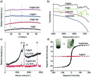 | ||
| Fig. 1 (a) XRD patterns and (b) FTIR spectra of Fe@NC, Fe@C, Fe@NC800 and Fe@C800; (c) Raman spectra and (d) magnetization curves of Fe@NC and Fe@NC800 at room temperature. | ||
Although there was almost no difference between the XRD patterns of Fe@NC and Fe@C, FTIR characterizations could clearly differentiate the two samples (Fig. 1b). The characteristic O–H vibration bands were all located at about 3300 cm−1. The two absorption bands at about 1610 cm−1 and 1360 cm−1 were ascribed to the antisymmetric and symmetric stretching vibrations of the OCO− groups in the sugar anions, respectively. For the Fe@NC sample, an obvious absorption band located at 1523 cm−1 corresponding to the N–H bending vibration could be observed. However, all these characteristic vibration bands disappeared when Fe@NC and Fe@C were calcined at 800 °C under inert atmosphere. Only a weak and broad band located at about 1600 cm−1 representing the skeleton vibration of the graphitic carbon could be observed,25 which suggested the extensive carbonization of the carbonous species in samples Fe@NC800 and Fe@C800.
Raman spectroscopy is often used to characterize carbon materials, which can illustrate microscopic structures according to the intensity ratio of the characteristic bands (D band and G band).26 So we also used Raman spectroscopy to trace the structure changes between Fe@NC and Fe@NC800. The original spectra presented in Fig. 1c show two characteristic bands for graphite located at approximately 1364 cm−1 (D band) and 1580 cm−1 (G band). This illustrates the existence of graphitic sp2 carbon networks in both samples.27,28 Furthermore, it is reported that the relative intensity of the D band to the G band, ID/IG, is inversely proportional to the crystallite size of graphite.29 The ratio of ID/IG for Fe@NC was 0.83, which was slightly larger than the ID/IG ratio of Fe@NC800 (0.55). This suggests that the graphitization extent of Fe@NC800 calcined at higher temperature was higher than that of the hydrothermally carbonized product Fe@NC. In addition, Fe@NC800 also exhibited a strong Raman G′ band at about 2704 cm−1 featuring the completely ordered 3D graphite,30 which further illustrated the high extent of graphitization of Fe@NC800.
The magnetic properties of Fe@NC and Fe@NC800 were also investigated using a magnetic property measurement system at room temperature. Fe@NC almost has no magnetic property because the main component in the sample is the complex composed of iron(III) and glucosaminic acid. However, the saturation magnetization value of Fe@NC800 was measured to be 23.9 emu g−1, which resulted from the generation of the iron metal during calcination. Besides, the hysteresis loop and remanence of Fe@NC800 presented in Fig. 1d were not obvious, indicating that it was superparamagnetic at room temperature. This magnetic property facilitated the recycling and reusability of the Fe@NC800 sample when it was used as a catalyst.
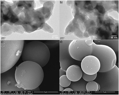
The morphology characterizations of Fe@NC and Fe@NC800 by TEM and SEM are presented in Fig. 2. For the TEM images of Fe@NC and Fe@NC800, iron nanoparticles could be clearly observed because they were coated with carbon. The SEM images of Fe@NC and Fe@NC800 showed many carbon microspheres contained in the two samples. No obvious differences between Fe@NC and Fe@NC800 could be observed just through morphology characterizations.
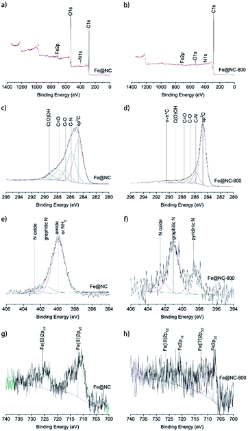
To further investigate the elemental composition and states of samples Fe@NC and Fe@NC800, XPS analysis was conducted and the results are presented in Fig. 3. The full XPS spectra shown in Fig. 3a and b illustrate that both samples Fe@NC and Fe@NC800 were composed of C, N, O and Fe. The oxygen content in Fe@NC was higher than the one in Fe@NC800, indicating that a large amount of oxygen-containing groups decomposed after the Fe@NC sample was calcined at 800 °C under nitrogen atmosphere. In order to know the changes to the electronic forms of the carbon, nitrogen, and iron atoms after calcination in nitrogen atmosphere at 800 °C, the C 1s, N 1s and Fe 2p XPS spectra were deconvoluted and presented. The C 1s XPS spectra shown in Fig. 3c and d could be deconvoluted into at least to five peaks at 284.7, 285.7, 286.6, 287.5, and 289.2 eV, corresponding to sp2 C, C–N, C–O, C![[double bond, length as m-dash]](https://www.rsc.org/images/entities/char_e001.gif) O and C(O)OH, respectively.31 As can be seen from the spectra, the peak at 284.8 eV was the main peak, and the peak became sharper after modification in nitrogen atmosphere at 800 °C, which indicated that the graphitization degree of carbon increased during the calcination process at high temperature. The peak at 285.7 eV suggested that nitrogen-containing functional groups existed on the surface of the materials. The N 1s XPS spectra of Fe@NC and Fe@NC800 were all deconvoluted into at least two peaks at 401.1 and 402.5 eV, which were attributed to graphitic N and N oxide.32 However, the peak located at 399.9 eV in the Fe@NC N 1s spectrum was the main peak, corresponding to pyridinic N. After calcination, the pyridinic N disappeared and the graphitic N became the primary nitrogen component.33,34 The Fe 2p XPS spectra of Fe@NC and Fe@NC800 clearly presented the valence changes of Fe before and after calcination. For the Fe@NC sample, the deconvoluted peaks located at 712.2 and 725.7 eV corresponded to Fe(III) 2p3/2 and Fe(III) 2p1/2.35,36 In contrast, the signal-to-noise ratio of the Fe@NC800 Fe 2p spectrum was too low, indicating that the iron content on the surface of Fe@NC800 was low and most of the iron was covered by carbon. The spectrum of Fe@NC800 illustrated that the zero iron species were the main component and there was still a small amount of trivalent iron potentially resulting from oxidation when the sample was exposed to air during characterization.
O and C(O)OH, respectively.31 As can be seen from the spectra, the peak at 284.8 eV was the main peak, and the peak became sharper after modification in nitrogen atmosphere at 800 °C, which indicated that the graphitization degree of carbon increased during the calcination process at high temperature. The peak at 285.7 eV suggested that nitrogen-containing functional groups existed on the surface of the materials. The N 1s XPS spectra of Fe@NC and Fe@NC800 were all deconvoluted into at least two peaks at 401.1 and 402.5 eV, which were attributed to graphitic N and N oxide.32 However, the peak located at 399.9 eV in the Fe@NC N 1s spectrum was the main peak, corresponding to pyridinic N. After calcination, the pyridinic N disappeared and the graphitic N became the primary nitrogen component.33,34 The Fe 2p XPS spectra of Fe@NC and Fe@NC800 clearly presented the valence changes of Fe before and after calcination. For the Fe@NC sample, the deconvoluted peaks located at 712.2 and 725.7 eV corresponded to Fe(III) 2p3/2 and Fe(III) 2p1/2.35,36 In contrast, the signal-to-noise ratio of the Fe@NC800 Fe 2p spectrum was too low, indicating that the iron content on the surface of Fe@NC800 was low and most of the iron was covered by carbon. The spectrum of Fe@NC800 illustrated that the zero iron species were the main component and there was still a small amount of trivalent iron potentially resulting from oxidation when the sample was exposed to air during characterization.
Catalytic activity
It has been established that heteroatoms doped in carbon could adjust the electron distribution of carbon atoms so that the catalytic activity of the carbon materials improved.37,38 Thus we expected that Fe@NC and Fe@NC800 would also have high catalytic activity in some traditional reactions. Firstly, the epoxidation of trans-stilbene with TBHP as the oxidant was selected as a probe reaction. The reaction results are listed in Table 1. In the absence of any catalyst, the conversion of trans-stilbene was only 9.7% (Table 1, entry 1). Under the same reaction conditions, the conversion of the substrate was increased about four times over that of the blank reaction by introducing Fe@NC as the catalyst (Table 1, entry 2). By increasing the amount of oxidant, the conversion of trans-stilbene and the selectivity for the epoxide product increased (Table 1, entry 3). This result illustrated that Fe@NC has excellent catalytic activity for the epoxidation of trans-stilbene. It was reported that graphitized nitrogen has very good catalytic activity.39 Therefore, Fe@NC-800, which possessed great amounts of graphitic nitrogen species, was evaluated as a catalyst even in the presence of a small amount of oxidant (380 μL TBHP). As was expected, Fe@NC-800 presented excellent conversion and selectivity (Table 1, entry 4). This result illustrated that Fe@NC indeed had good catalytic oxidation activity for the trans-stilbene epoxidation, but the glucosaminic acid in Fe@NC perhaps consumed a portion of the oxidant during the oxidation process. When Fe@NC was calcined at high temperature, glucosaminic acid converted into a nitrogen-containing carbon material so that only a small amount of oxidant could get a high conversion of the substrate. Along with the increase in the amount of oxidant, the conversion of the substrate even reached 97.7% and the selectivity towards the epoxide product remained above 97% (Table 1, entry 5). When the iron species in the Fe@NC800 sample were dissolved and washed with hydrochloric acid (almost no iron elements were detected by XPS analysis (Fig. S1†)), the catalytic activity and selectivity still remained (Table 1, entry 6). However, if there was no catalyst in the reaction system, only 23.8% conversion and 36.1% selectivity towards epoxide were achieved even in the presence of sufficient oxidant (Table 1, entry 7). In order to further confirm the essential catalytic function of the graphitic nitrogen in Fe@NC800, the Fe@C800 sample without nitrogen dopant was used as a catalyst under the same optimal reaction conditions. Unsurprisingly, the conversions of stilbene were very low (Table 1, entries 8 and 9). These control experiments suggested that the iron species in Fe@NC800 were not the key active sites for this reaction. According to the XPS characterizations and the reaction results, it could be concluded that graphitic nitrogen components were an essential factor in the catalytic oxidation activity of Fe@NC800.39 However, for Fe@NC, the catalytic system may be homogeneous because the filtrate of the Fe@NC dispersion could also catalyse the epoxidation (Table S1†). In addition, according to literature reports, iron(III) complexes could transfer the oxygen atom from the peroxide to the alkenes to generate epoxides40,41 so iron(III) species in Fe@NC were essential factors for high catalytic ability in the epoxidation of alkenes with peroxide.| Entry | Catalyst | TBHP (μL) | Con. (%) | Sel. (%) | |
|---|---|---|---|---|---|
| 1 | 2 | ||||
| a Reaction conditions: trans-stilbene 1 mmol, catalyst 10 mg, CH2Cl2 2 mL, urea 0.5 mmol, 373 K. | |||||
| 1 | — | 380 | 9.7 | 95.7 | 4.3 |
| 2 | Fe@NC | 380 | 38.9 | 95.4 | 4.6 |
| 3 | Fe@NC | 800 | 95.6 | 96.3 | 3.7 |
| 4 | Fe@NC800 | 380 | 87.1 | 97.7 | 2.3 |
| 5 | Fe@NC800 | 800 | 97.7 | 97.6 | 2.4 |
| 6 | Fe@NC800(HCl) | 800 | 99.4 | 96.2 | 3.8 |
| 7 | — | 800 | 23.8 | 36.1 | 63.9 |
| 8 | Fe@C800 | 380 | 29.8 | 96.6 | 3.4 |
| 9 | Fe@C800 | 800 | 33.8 | 96.4 | 3.6 |
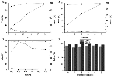
We also investigated the reaction results of the trans-stilbene epoxidation with Fe@NC-800 as a catalyst under different reaction conditions (Fig. 4). It is obvious that the yield of trans-stilbene epoxide was merely 8.6% in the first hour and it gradually increased on extending the reaction time. The final yield went up to 94.6% when the reaction was carried out for 24 hours. With the increase of the reaction time, the selectivity of benzaldehyde decreased and the selectivity of trans-stilbene epoxide increased gradually. According to Fig. 4c, when 0.5 mmol urea was added to the reaction, the yield of the epoxide reached the maximum and then it decreased with the increased urea content. It indicated that the moderate basic conditions favoured the catalytic epoxidation. Fig. 4b shows the relationship between the yield of trans-stilbene epoxide, the amount of oxidant and the selectivity of products. Evidently, the conversion of trans-stilbene and the selectivity towards the aimed product epoxide increased with the amount of TBHP. In addition, the catalytic activity of Fe@NC-800 in the epoxidation of trans-stilbene just dropped slightly after five times and the selectivity was still above 95% (Fig. 4d). XPS analysis of the reused Fe@NC-800 indicated that iron species in the catalyst were oxidized to iron oxide and the content of graphitic N species decreased (Fig. S2†), which may have resulted in the decrease in catalytic activity.
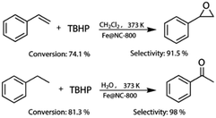
More importantly, Fe@NC-800 also exhibited high catalytic activity in the oxidation of styrene and ethylbenzene. As can be seen in Fig. 5, in the styrene epoxidation, 74.1% styrene conversion and 91.5% epoxide selectivity could be achieved. In the oxidation of ethylbenzene, it can attain 81.3% conversion and 98% selectivity to acetophenone. These results illustrated that Fe@NC800 was an ideal magnetic and sustainable catalyst for the C–H bond oxidation. In addition, Fe@NC also exhibits considerable catalytic activity in the two reactions (Fig. S3†).
We also analysed the total energy changes during the whole proposed catalytic process by DFT calculations. As presented in Fig. 6, the oxidant TBHP firstly adsorbed on the surface of the carbon catalyst and then the activated carbon catalyst containing the peroxide group generated and TBHP was transformed into tert-butyl alcohol (step I and II). Secondly, the trans-stilbene was adsorbed on the surface of the activated catalyst and the one oxygen atom in the peroxide group anchoring on the ortho-carbon atom of nitrogen in the carbon catalyst was transmitted to trans-stilbene to generate the epoxide. The peroxide group was then transformed into a hydroxyl group (step III and IV). The hydroxyl group in the deactivated carbon catalyst could be oxidized to peroxide group by another TBHP molecule. The DFT calculations indicated that the existence of iron atoms facilitated the adsorption of TBHP on the surface of the nitrogen-containing carbon and decreased the generation energy of the peroxide group (OOH) located at the ortho-position carbon atom of nitrogen (step II). Consequently, iron species existing in the carbon catalyst promoted the catalytic activity of the nitrogen-containing carbon by facilitating the initial step of the whole catalytic process.
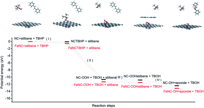 | ||
| Fig. 6 The changes of potential energy in some important reaction steps with nitrogen-containing carbon and magnetic nitrogen-containing carbon as a catalyst. | ||
Conclusions
A kind of magnetic nitrogen-containing carbon catalyst was synthesized by hydrothermal carbonization and high temperature calcination with NAG and iron nitrate as precursors. The carbon catalyst exhibited excellent catalytic C–H oxidation activity, such as in the epoxidation of stilbene and styrene, and the oxidation of ethylbenzene. The recyclability experiments indicated that the catalyst was stable and easily separated from the catalytic system due to its magnetic property. The active sites promoting the catalytic C–H oxidation were the graphitic N species existing in the carbon structure. The DFT calculations indicate that the iron species were not an essential factor but acted as a promoter in the catalytic performance of the catalyst. This study will expand the application of biomass-based heteroatom-containing compounds.Conflicts of interest
There are no conflicts to declare.Acknowledgements
This work was supported by the Hebei provincial Natural Science Foundation (No. B2017201084), the Hebei provincial technology foundation for High-level talents (No. CL201601), the One Hundred Talent Project of Hebei Province (No. E2016100015), and the science technology research and development guidance program project of Baoding City (No. 16ZF027). The DFT calculations were supported by the High Performance Computing Center of Hebei University. We also thank Dr Liang Yu for the discussion about DFT calculations.References
- B. S. Lane and K. Burgess, Chem. Rev., 2003, 103, 2457–2474 CrossRef CAS PubMed.
- Q. H. Xia, H. Q. Ge, C. P. Ye, Z. M. Liu and K. X. Su, Chem. Rev., 2005, 105, 1603–1662 CrossRef CAS PubMed.
- C. C. Winterbourn, Toxicol. Lett., 1995, 82, 969–974 CrossRef PubMed.
- X. Li, X. Pan and X. Bao, J. Energy Chem., 2014, 23, 131–135 CrossRef CAS.
- M. Aleksandrzak, W. Kukulka and E. Mijowska, Appl. Surf. Sci., 2017, 398, 56–62 CrossRef CAS.
- M.-C. Kim, D. Lee, S. H. Jeong, S.-Y. Lee and E. Kang, ACS Appl. Mater. Interfaces, 2016, 8, 34317–34326 CAS.
- W. J. Pech-Rodríguez, D. González-Quijano, G. Vargas-Gutiérrez, C. Morais, T. W. Napporn and F. J. Rodríguez-Varela, Appl. Catal., B, 2017, 203, 654–662 CrossRef.
- J. Tang, D. Chen, C. Li, X. Yang, H. Liu and J. Yang, RSC Adv., 2017, 7, 3455–3460 RSC.
- Y. Zhai, Z. Zhu and S. Dong, ChemCatChem, 2015, 7, 2806–2815 CrossRef CAS.
- S. Agnoli and M. Favaro, J. Mater. Chem. A, 2016, 4, 5002–5025 CAS.
- P. Ai, M. Tan, N. Yamane, G. Liu, R. Fan, G. Yang, Y. Yoneyama, R. Yang and N. Tsubaki, Chem.–Eur. J., 2017, 8252–8261 CrossRef CAS PubMed.
- T. Asefa and X. Huang, Chem.–Eur. J., 2017, 10703–10713 CrossRef CAS PubMed.
- G. Wang, H. Peng, X. Qiao, L. Du, X. Li, T. Shu and S. Liao, Int. J. Hydrogen Energy, 2016, 41, 14101–14110 CrossRef CAS.
- Y.-N. Zhu, C.-Y. Cao, W.-J. Jiang, S.-L. Yang, J.-S. Hu, W.-G. Song and L.-J. Wan, J. Mater. Chem. A, 2016, 4, 18470–18477 CAS.
- H.-S. Park, S.-B. Han, D.-H. Kwak, G.-H. Lee, I.-A. Choi, D.-H. Kim, K.-B. Ma, M.-C. Kim, H.-J. Kwon and K.-W. Park, ChemSusChem, 2017, 2202–2209 CrossRef CAS PubMed.
- B. Frank, M. Morassutto, R. Schomäcker, R. Schlögl and D. S. Su, ChemCatChem, 2010, 2, 644–648 CrossRef CAS.
- D. Kong, W. Yuan, C. Li, J. Song, A. Xie and Y. Shen, Appl. Surf. Sci., 2017, 393, 144–150 CrossRef CAS.
- L. Wang, W. Jia, X. Liu, J. Li and M. M. Titirici, J. Energy Chem., 2016, 25, 566–570 CrossRef.
- W. Li, Y. Gao, W. Chen, P. Tang, W. Li, Z. Shi, D. Su, J. Wang and D. Ma, ACS Catal., 2014, 4, 1261–1266 CrossRef CAS.
- G. Yu, B. Sun, Y. Pei, S. Xie, S. Yan, M. Qiao, K. Fan, X. Zhang and B. Zong, J. Am. Chem. Soc., 2010, 132, 935–937 CrossRef CAS PubMed.
- X. Chen, Y. Liu, F. M. Kerton and N. Yan, RSC Adv., 2015, 5, 20073–20080 RSC.
- F. D. Bobbink, J. Zhang, Y. Pierson, X. Chen and N. Yan, Green Chem., 2015, 17, 1024–1031 RSC.
- P. Wang, X. Wang, S. Yu, Y. Zou, J. Wang, Z. Chen, N. S. Alharbi, A. Alsaedi, T. Hayat, Y. Chen and X. Wang, Chem. Eng. J., 2016, 306, 280–288 CrossRef CAS.
- L. Zhang, J. Jiang, C. Zhang, B. Wu and F. Wu, J. Power Sources, 2016, 331, 247–257 CrossRef CAS.
- T. Van Khai, H. G. Na, D. S. Kwak, Y. J. Kwon, H. Ham, K. B. Shim and H. W. Kim, J. Mater. Chem., 2012, 22, 17992–18003 RSC.
- M. R. Snowdon, A. K. Mohanty and M. Misra, ACS Sustainable Chem. Eng., 2014, 2, 1257–1263 CrossRef CAS.
- P. K. Chu and L. Li, Mater. Chem. Phys., 2006, 96, 253–277 CrossRef CAS.
- E. Gracia-Espino, X. Jia and T. Wågberg, J. Phys. Chem. C, 2014, 118, 2804–2811 CAS.
- M. A. Pimenta, G. Dresselhaus, M. S. Dresselhaus, L. G. Cançado, A. Jorio and R. Saito, Phys. Chem. Chem. Phys., 2007, 9, 1276–1290 RSC.
- K. S. Subrahmanyam, A. K. Manna, S. K. Pati and C. N. R. Rao, Chem. Phys. Lett., 2010, 497, 70–75 CrossRef CAS.
- R. Chen, L. Li, Z. Liu, M. Lu, C. Wang, H. Li, W. Ma and S. Wang, J. Air Waste Manage. Assoc., 2017, 67, 713–724 CAS.
- Y. Gao, X. Chen, J. Zhang and N. Yan, ChemPlusChem, 2015, 80, 1556–1564 CrossRef CAS.
- P. Tang, Y. Gao, J. Yang, W. Li, H. Zhao and D. Ma, Chin. J. Catal., 2014, 35, 922–928 CrossRef CAS.
- M. Xiao, J. Zhu, L. Feng, C. Liu and W. Xing, Adv. Mater., 2015, 27, 2521–2527 CrossRef CAS PubMed.
- H. Zhao, Q. Zhu, Y. Gao, P. Zhai and D. Ma, Appl. Catal., A, 2013, 456, 233–239 CrossRef CAS.
- H. Lida, D. Elaheh, G. I. Douglas and G. C. V. Jonathan, Nanotechnology, 2017, 28, 095707 CrossRef PubMed.
- T. Liu, Y. Li, N. Peng, Q. Lang, Y. Xia, C. Gai, Q. Zheng and Z. Liu, J. Environ. Manage., 2017, 197, 151–158 CrossRef CAS PubMed.
- M. H. Naveen, K. Shim, M. S. A. Hossain, J. H. Kim and Y.-B. Shim, Adv. Energy Mater., 2017, 7 DOI:10.1002/aenm.201602002.
- Y. Gao, G. Hu, J. Zhong, Z. Shi, Y. Zhu, D. S. Su, J. Wang, X. Bao and D. Ma, Angew. Chem., Int. Ed., 2013, 52, 2109–2113 CrossRef CAS PubMed.
- E. Ferrari and M. Saladini, J. Inorg. Biochem., 2004, 98, 1002–1008 CrossRef CAS PubMed.
- A. M. Zima, O. Y. Lyakin, R. V. Ottenbacher, K. P. Bryliakov and E. P. Talsi, ACS Catal., 2017, 7, 60–69 CrossRef CAS.
Footnote |
| † Electronic supplementary information (ESI) available. See DOI: 10.1039/c7ra10226g |
| This journal is © The Royal Society of Chemistry 2017 |

