 Open Access Article
Creative Commons Attribution 3.0 Unported Licence
The phase, morphology and surface characterization of Ti–Mo alloy films prepared by magnetron sputtering
Gang Liu,
Yanqing Yang *,
Xian Luo,
Bin Huang and
Pengtao Li
State Key Lab of Solidification Processing, Northwestern Polytechnical University, Xian 710072, PR China. E-mail: yangyanqingdaoshi@163.com; Fax: +86 29 88460499; Tel: +86 29 88460499
First published on 13th November 2017
Abstract
Magnetron sputtering is a physical vapor deposition process which allows the formation of metastable materials because of the particle bombardment process. Ti–Mo alloys are typical biomedical β-Ti alloys because of the remarkable β-stabilizing effect and the favorable safety of the Mo element. In this paper, Ti–15 wt% Mo and Ti–30 wt% Mo alloy films prepared by magnetron sputtering are studied. The substrate temperatures are 50 °C, 100 °C, 200 °C and 300 °C, respectively, which are far below the β-transus temperatures of Ti–Mo alloys. The two films both show metastable β-Ti growth at 50 °C and 100 °C, but have different phase evolutions as the substrate temperature further rises. The diversity is attributed to the different stabilities of metastable β growth in the two films. The different morphology evolutions with the increasing substrate temperature between the two films are discussed. The natural surface oxidation layers of the two films are analyzed by XPS.
1. Introduction
Titanium (Ti) and its alloys offer a wide range of adaptable structures for biomedical applications.1 Interest in β-Ti alloys as biomaterials was derived from the excellent combination of good mechanical properties with low elastic modulus (E) close to that of human bone (E = 10–40 GPa (ref. 2 and 3)), leading to better bone remodeling and osseointegration processes compared with α- and α + β-Ti alloys.4 It is known that the properties of β-Ti alloys are greatly affected by alloying elements. On one hand, solid-solution strengthening is the most important strengthening mechanisms involved in these alloys. On the other hand, by the addition of enough β stabilizing elements (Mo, Nb, V, Fe, Ta, etc.), metastable β-Ti alloys can be produced by the fast cooling process following the heating treatment above Tβ (β transus temperature). A series of β-Ti alloys have been developed, such as Ti–Mo,5–12 Ti–Nb,13 Ti–Mo–Nb,14 and Ti–Nb–Zr–Fe (Ta).15 Among these alloys, metastable Ti–Mo alloys receive much attention because of the remarkable β-stabilizing effect and the favorable safety of the Mo element. According to Bania et al.,7 only 10 wt% of Mo content is needed to fully stabilize the β phase at room temperature in a quenched Ti–Mo alloy. Ho et al.5 found that the cast binary Ti–(10–20) wt% Mo alloys show metastable β-Ti growth, while those with less than 10 wt% Mo content exhibit a martensitic transformation from the β phase to orthorhombic α′′ or hexagonal α′ phase.Magnetron sputtering of thin films has developed into a mature field of physical vapor deposition (PVD) technologies. The relations between deposition parameters and film structures are of fundamental importance because understanding these relations helps to control the film growth.16–23 During the sputtering process, the atom configurations on the substrate are essentially depend on two parameters: (i) the ratio Ts/Tm which controls the conventional heating process, in which Ts and Tm are the substrate temperature and the melting temperature of deposited materials, respectively, and (ii) the energy delivered to growing surface of the film by particle bombardment (atomic scale heating), which is related to the deposition conditions, such as working pressure, substrate bias or sputtering power.24–26 It is necessary to note that the atomic scale heating stimulates highly non-equilibrium cooling processes which results in the formation of metastable and unstable materials. This is one of the main reasons for the formation of special structures of the films under particle bombardment.
According to conventional heating processes, it is reasonable to affirm that β-Ti phase would be formed in Ti alloy films when they are deposited above Tβ. However, in practical cases, the deposition above Tβ is seldom used because of two issues. One is the interface reaction between the film and the substrate at such high Ts, the other is a subsequent stabilization of β-Ti phase to low temperatures when cooled down. To the best of our knowledge, Musil et al.27 firstly reported the formation of metastable β-Ti alloy films formed by magnetron sputtering. Because of atomic scale heating from particle bombardment, β-type Ti–10 wt% Cr and Ti–10 wt% Fe films can be formed when Ts is below 100 °C (Tβ,Ti–Cr ≥ 667 °C,27 Tβ,Ti–Fe ≥ 595 °C (ref. 28)). Regent et al.29 reported the same result for Ti–10 at% Mo alloy films on a unheated substrate. These results show a feasible way to form metastable β-Ti alloy films at a low Ts (Ts < Tβ), which avoids the two issues mentioned above. However, it gives rise to another two problems. The first is the formation of β-Ti determined by particle bombardment on the growing surface of the films during deposition. Enough bombardments are desired to provide a sufficient energy for the adatoms to form high temperature β phase at the low Ts range, while too much bombardments cause interface local heating, implantation, vacancy or disruption of crystallizations in the films. For instance, from XRD results, Ti–10 wt% Cr alloy films have a α-Ti growth without substrate bias, but change into an amorphous growth at −150 V.23 Also, they could have a β-Ti growth when under proper bombardment conditions.27 The second problem is to keep the metastable β-Ti phase in the films during the whole deposition, which depends on alloy composition of the films and the Ts. Substrate heating could partly decrease defects, and improve film/substrate interface bonding, crystallinity or structural density of the films, but it may cause the decomposing of metastable β-Ti phase during the deposition.30 Therefore, the stability of metastable β-Ti phase in the sputter-deposited films needs to be investigated. This work is mainly devoted to the second problem.
In the biomedical field, however, magnetron sputtering is still a novel technique. Nanostructural surfaces of biomedical Ti alloys are interesting when it comes to the bone/Ti alloy implant interfaces. The high surface energy of nanomaterials leads to desirable cellular responses and high osseointegration.31 Ivanova et al.32 studied the bioactivity of Ti films with different thickness (3, 12, or 150 nm), and revealed a direct link between the nanoscale surface roughness and cell attachment of the films. More recently, β-Ti alloy films have attracted more attentions because of enhanced biomedical properties of β-Ti alloys compared with α- or α + β-Ti alloys. Coating of less biocompatible materials with β-Ti alloy films has became an alternative way to improve the biomedical properties.33,34 For instance, Tallarico et al.34 prepared biomedical β-type Ti–Nb–Zr alloy coatings on stainless steels by magnetron sputtering, and investigated the growth and surface chemistry of the coatings. Gonzalez et al.33 studied the morphology, microstructure and compositions of biomedical β-type Ti–Nb alloy films deposited at 200 °C, with 15 at%, 20 at%, 30 at% and 40 at% Nb content, respectively. Besides these biomedical applications, β-Ti alloy films can also serve as hydrogen storage materials because hydrogen has a high solubility in β-Ti alloys. Shi et al.35,36 showed that Ti–Mo alloy films have an improvement in hydrogen storage capacities compared to pure Ti films, and the resistance against embrittlement of the films was enhanced because of the ductility of β-Ti phase and the reduction of the hydrogenise formation. Magnetron sputtering allows the production of metastable β-Ti alloy films, therefore, it is now prompting new researches for those applications. Controlling the metastable β-Ti growth in the films is primarily important, however, very complex, because it is highly related to several conditions, such as Ts, particle bombardment and the compositions of the films. Understanding these is necessary for determining preparation parameters, film compositions, and service temperatures of the films in practical applications.
Ti–15 wt% Mo and Ti–30 wt% Mo alloys are both popular biomedical Ti–Mo alloys,6,37 however, their as-sputtered structures have yet not been studied. In the present work, Ti–15 wt% Mo and Ti–30 wt% Mo alloy films formed by magnetron sputtering technique are investigated, respectively, with main concerns on phase, morphology and surface characterization of the films. Tβ, of pure Ti is 882 °C and the approximate amount of β transus reduction per wt% of Mo addition is about 8.3 °C. Therefore, Tβ of Ti–15Mo and Ti–30Mo can be estimated as 758 °C and 633 °C, respectively.38 The Ts during deposition is 50 °C, 100 °C, 200 °C and 300 °C, respectively. The metastable β-Ti growth of the two films are obtained at 50 °C and 100 °C, but they show different phase evolutions as the Ts further rises, which is attributed to the different stability of metastable β-Ti phase. Accordingly, the different morphology evolutions in the Ts range between the two films are shown and discussed, respectively. Besides, surface characterization is an important topic of biomedical materials because it plays a key role in the living tissue response to the metal presence. Considering that Ti and Mo elements are both chemically reactive, nature surface oxidation layers of the films are analyzed using X-ray photoelectron spectroscopy (XPS).
2. Experimental
We deposited the Ti–Mo alloy films on silicon (Si) (100) substrates by direct current magnetron sputtering. The alloy targets of two compositions were used: Ti–15 wt% Mo and Ti–30 wt% Mo, which were prepared by melting appropriate amounts of Ti and Mo powders. Hereafter, Ti–15 wt% Mo and Ti–30 wt% Mo will be simplified as Ti–15Mo and Ti–30Mo. We used high-purity (99.999%) argon as the sputtering gas. The base pressure was 5.0 × 10⁻⁴ Pa and the sputtering pressure was 0.8 Pa. Before starting the actual deposition, we pre-sputtered the target for 20 min with a shutter covering the substrate. The actual deposition time of the films was 120 min. The target–substrate separation was kept at 40 mm. The sputtering power was 180 W. The substrate temperatures were 50 °C, 100 °C, 200 °C, and 300 °C, respectively. Three samples were prepared for each condition. After each deposition, we kept the Ts for 20 min and then we cooled the films to room temperature in the vacuum.We analyzed phase, texture, morphologies of the films using X-ray diffraction (XRD) operated on PANAlytical X'Pert PRo MPD instrument (Almelo, Netherlands), Tescan MIRA3 XMU scanning electron microscope (SEM; Brno, Czech Republic), and FEI Tecnai™ F30 G2 transmission electron microscope (TEM; Hillsboro, OR) with accelerating voltage of 300 kV, respectively. Surface roughness of the films were measured using Shimadzu SPM-9600 atomic force microscope (AFM; Kyoto, Japan). The instrument was operated in the contact mode, and the measuring range was 5 × 5 μm2. Bulk compositions of the films were detected by a SEM-based INCA energy dispersive spectrometer (EDX) with an X-MAX detector (Oxford Instruments, UK). The calibration was performed using a Ti standard, and the quantization was processed with a built-in XPP correction procedure. Surface chemical compositions of the films were analyzed using Thermo Fisher X-ray photoelectron spectroscopy (XPS; America) with a Al Kα (hν = 1486.6 eV) monochromatized focused X-ray source. The spectrometer was calibrated against the reference binding energies (BEs) of clean Cu (Cu 2p3/2 at 932.6 eV), Au (Au 4f7/2 at 84.0 eV) and Ag (Ag 3d5/2 at 368.2 eV). The analyzed area is 400 × 400 μm2. In addition to the survey spectrum (pass energy of 200 eV, step energy of 1 eV), the following core levels were systematically recorded at higher energy resolution (pass energy of 50 eV, step energy of 0.1 eV): C 1s, O 1s, Ti 2p, Mo 3d. The binding energy positions were determined through curve fitting with the mixed 30% Lorentzian and 70% Gaussian curves and Shirley baselines using the Avantage software. Core levels were calibrated by the standard C 1s peak at 284.8 eV.
3. Results and discussion
Fig. 1(a) shows typical XRD patterns of the Ti–15Mo alloy films at different Ts. It can be seen that (i) the Ti–15Mo alloy films have a metastable β growth at 50 °C and 100 °C, and (ii) the orthorhombic α′′ phase was formed at a higher Ts. Fig. 1(b) shows close up of the reflections from 36° to 41°, in which a single β(110) peak is observed below 100 °C, and a composition of β(110) and α′′(111) peaks appears at higher Ts. The (110) plane is the densest plane of β-Ti phase which has a body-centred cubic structure. Increasing the Ts is supposed to help the (110) growth of the film because of the reduced surface energy of the film.39 However, the β(110) peak is decreased as the Ts rises in this work, which is also found in our previous work for Ti–5Al–4Mo–4Cr–2Zr–2Sn alloy films.30 This is because, with the occurrence of the phase evolution, the growth of the film is determined by a combined effect of the reduced surface energy of the film and the interfacial energy between different phases. The α′′ phase is a well-known transition phase during the transformation from β-Ti to α-Ti. The formation of α′′ phase indicates that the metastable β-Ti phase has changed because of the activation energy provided by heating substrate above 100 °C. Therefore, in Ti–15Mo alloy films, a sufficiently low Ts (no more than 100 °C) is necessary to stabilize the metastable β-Ti phase during the whole deposition. We can also infer that metastable β-type Ti–15Mo alloy films can not be subjected to an excessive service temperature, such as the hydrogenation temperature in hydro-treating,36 to prevent the decomposing of β-Ti phase. Fig. 2(a) shows the bright field (BF) image and the selected area electron diffraction (SAED) pattern of the Ti–15Mo film at 100 °C. The pattern further confirms the β-Ti growth of the film at this temperature because the four rings correspond to (110), (200), (211) and (220) reflections of β-Ti. The polycrystalline orientation of the crystallites shows the adatom diffusion is negative at 100 °C, so the crystallization follows the random orientations of nuclei.40 The formation of β phase suggests that the particle bombardment conditions provide a sufficient energy for the adatoms to form the high-temperature β phase. The fast dissipation of this energy in close proximity of every incident atom results in extremely fast cooling and freezing of the β-Ti phase on the growing surface of the films during the deposition.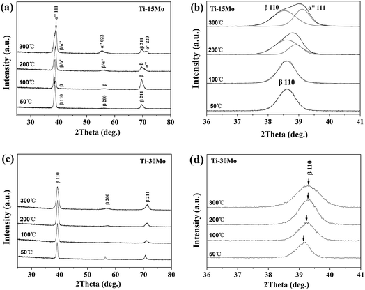 | ||
| Fig. 1 The XRD patterns of the Ti–15 wt% Mo and Ti–30 wt% Mo alloy films at different Ts: (a, c) the whole patterns; (b, d) the close up from 36° to 41°, respectively. | ||
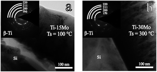 | ||
| Fig. 2 The BF image and the SAED pattern of (a) the Ti–15 wt% Mo film at 100 °C and (b) the Ti–30 wt% Mo film at 300 °C. | ||
Fig. 1(c) shows typical XRD patterns of the Ti–30Mo alloy films at different Ts. The films could keep a β-type growth in the whole Ts range. This result shows that (i) the stability of metastable β-Ti phase is improved by increasing the content of isomorphous Mo element, and (ii) the substrate heating (Ts) does not supply enough activation energy for a phase change or the change is extremely sluggish. Fig. 1(d) displays the single β(110) peaks at different Ts, showing right position shifts and broadenings as the Ts rises. The position shifts can be related to the change of lattice parameter due to alloying at different Ts. The Mo elements could not only incorporate in the β-Ti lattices, but also exist at the grain boundary in a state of amorphousness or very tiny crystallites. In the latter case, their qualities are so small that the diffraction intensity is below the detection limit. The atomic radius of Mo and Ti elements are 1.36 Å and 1.47 Å, respectively. As the Ts rises, the enhanced solid solution of those free Mo elements into the Ti matrix tends to decrease the lattice parameter of Ti matrix and right shift the peaks. The slight peak broadening with the Ts (Fig. 1(d)) is caused by the decreasing of the crystalline size which is attributed to impurity segregations. The impurity incorporations are hardly avoidable during real depositions. At higher Ts, the impurity segregations to surfaces and grain boundaries could suppress crystalline growth of the fundamental structure.40 Fig. 2(b) shows the BF image and corresponding SAED pattern of the β-Ti growth of the film at 300 °C, suggesting certain orientation growth at this temperature.
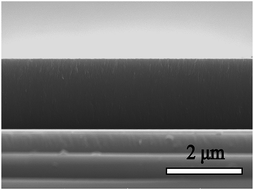
Besides the β phase growth, another important issue of these films is their morphology evolutions which particularly arise in the PVD process. Fig. 3 and 4 show the SEM results of surface and fracture morphologies of the Ti–15Mo and the Ti–30Mo alloy films, respectively, suggesting that the morphology evolution of the two films have some similarities with the increasing Ts. When the Ts ranges from 50 °C to 200 °C, they both present a relatively smooth surface morphology with small surface particles, and a columnar fracture morphology with distinct boundaries. When the Ts rises to 300 °C, the surface particles of two films both grow up greatly, leading to a coarse and roughness surface structure, and the surface and fracture morphologies both become dense at this temperature. Fig. 5 shows the AFM average surface roughness (Ra) of the two films both sharply rises at 300 °C, which is in accordance with the SEM observations.
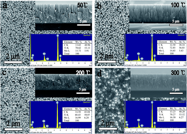 | ||
| Fig. 3 The SEM surface and fracture images and the EDX results of the Ti–15 wt% Mo alloy films at different substrate temperature. | ||
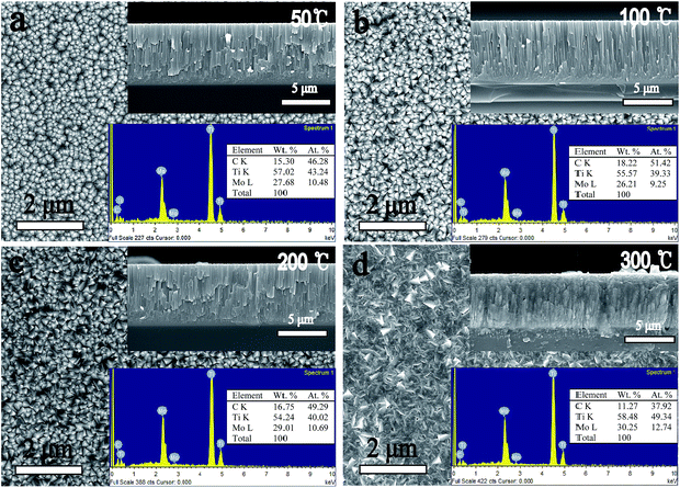 | ||
| Fig. 4 The SEM surface and fracture images and the EDX results of the Ti–30 wt% Mo alloy films at different substrate temperature. | ||
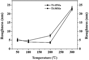 | ||
| Fig. 5 The AFM surface roughness of the Ti–15 wt% Mo and Ti–30 wt% Mo films at different Ts, respectively. | ||
One problem is that the Ti–15Mo alloy film can not keep the β-type growth above 100 °C. In spite of its β-type growth at 50 °C, Ti–15Mo alloy film shows a poor structure with voids and open boundaries, see Fig. 3(a), which is the microstructure of zone 1 in the low Ts range of the Movchan and Demchishin model.41 This poor structure is rather friable and not suitable for practical application, and the voids absorb impurities in the film interior which degrades the corrosion performance of the metallic film. Thus, it is necessary to improve the growth of Ti–15Mo alloy film deposited at 50 °C. According to the structure zone model (SZM) from Thornton,42,43 the zone 1 growth of the film can change into a dense and smooth non-columnar zone T growth at the low Ts range in assistance of the effect of particle bombardment. The principle of this low temperature sputtering of films with zone T growth is based on replacement of the equilibrium substrate heating by non-equilibrium atomic scale heating. Therefore, the poor structure of the Ti–15Mo film deposited at 50 °C can be improved without compromising its metastable β growth by enhancing the particle bombardment, such as decreasing the working pressure, rising the sputtering power, or using the substrate bias. Fig. 6 shows the fracture image of the Ti–15Mo alloy film deposited at 50 °C when the low working pressure 0.2 Pa and the substrate bias −100 V were used. The film structure is significantly improved because of the disappearance of voids and columnar growth mode, which can be defined as the microstructure of zone T in the SZM from Thornton.42,43
When the Ts rises to 300 °C, the morphologies of two films become completely different, as shown in Fig. 3(d) and 4(d). The first difference is that the surface particles of the two films have completely different shape features at 300 °C. This can be related to the different phases of the two films at 300 °C. As a comparison, Zhang et al.44 showed that the surface particles of β-type Ti–Cr alloy films have similar spherical shape features under their experimental conditions, with 10 at%, 25 at%, 40 at% Cr contents, respectively. The second difference is that the columnar fracture morphology of Ti–15Mo alloy film disappears, which is replaced by a smooth and noncolumnar one, while that of the Ti–30Mo alloy film keeps at 300 °C. The SZMs from Movchan and Demchishin41 and Thornton42,43 qualitatively represent the microstructure of single-phase films with the increasing Ts/Tm. These models, however, strongly change when impurities or additives are incorporated in the film.39,40 This is because the impurities or additives may lead to the formation of a segregation layer40,45 or a new phase39,46 on the phase boundaries of the forming majority phase, which would change the growth mode of the films. In the present work, Ti–30Mo alloy films have a single phase in the whole Ts range, and the transition from a poor columnar growth to a dense columnar growth is consistent with the transition from zone 1 to zone 2 in the SZMs. However, it must be noted that the impurity incorporation or the co-deposited Mo elements have inevitably influenced the growth of the film during deposition, although the columnar mode of the film is sustained. For Ti–15Mo alloy films, the formation of new phase disturbs the columnar growth of the films, and leads to a structure with no distinct columnar growth. The similar results were found in Zr–Cu–N nanocomposite coatings.47 At a low Cu content of 1–2 at%, the film exhibits a columnar growth, while at a high Cu content of 20 at%, Cu as an additive phase, which is detected by the XRD, can block the growth of all grains already in the coalescence stage and results in fine globular structure of the film. Barna et al.46 investigated the microstructures of Al1−xPtx alloy films with 0 ≤ x ≤ 0.4 using TEM, and found the formation of Al5Pt and Al6Pt intermetallic phases on the boundaries of Al islands. Equiaxial grains of the minority phase decorate grain boundaries and triple points, thus decrease migration of grain boundaries and grain coarsening.48 These results all show that the formation of new phase can strongly affect the development of the film structure. Therefore, Ti–15Mo and Ti–30Mo alloy films have different structural features at 300 °C.
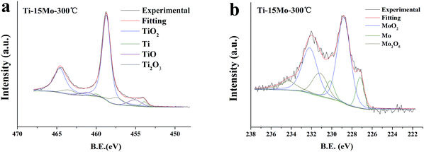
The EDX and XPS techniques are used to acquire bulk and surface compositions of the two films, respectively. It is known that the EDX detection depth is up to several micrometers, while the XPS detection depth is only nanoscared from the film surface. Typical EDX spectra and corresponding composition results of the Ti–15Mo and the Ti–30Mo alloy films at different substrate temperatures are inserted in Fig. 3 and 4, respectively. Besides major Ti and Mo peaks, C peaks are also detected by EDX. Fig. 7 provides the XPS survey spectra of the two films deposited at 100 °C and 300 °C, respectively, where the C and O peaks are both detected. These impurities in the films mainly come from two sources. The first is the adsorption of the residual gas of the vacuum system during deposition, which affects the crystalline growth and the texture evolution of the films,39 or leads to the intrinsic compressive stress in the films.49 The other is the adsorption of impurities when the films are exposed in the air after deposition. The C component is commonly from the adsorption of hydrocarbon molecules or C-containing gas molecules, and the O component is from the formation of metallic oxides and the adsorption of oxygen or oxygen-containing gas molecules.34 Fig. 8 shows the typical XPS Ti 2p and Mo 3d spectra of the Ti–15Mo films deposited at 300 °C, respectively. Ti 2p spectra (Fig. 8(a)) are fitted by 4 components associated to metallic Ti, TiO, Ti2O3, and TiO2, while only the TiO2 component is pronounced for all films. Mo 3d spectra (Fig. 8(b)) are fitted by 3 components associated to Mo, MoO2, Mo2O5. The MoO2 component is more prominent for all films, although metallic component and Mo2O5 are also noticeable. These results show that the surfaces of the films are naturally oxidized in the air. These partially oxidized surface layers are desirable because they could provide great corrosion protection for implant materials.
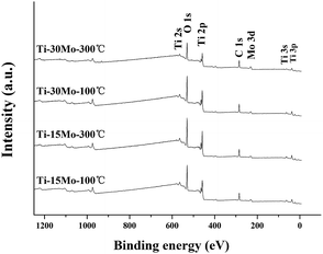 | ||
| Fig. 7 The wide scan XPS spectra of the Ti–15 wt% Mo and Ti–30 wt% Mo alloy films deposited at 100 °C and 300 °C, respectively. | ||
The EDS and XPS alloy compositions for the two films at 100 °C and 300 °C are shown in Table 1, respectively, where the C and O components are excluded. The comparison between EDS and XPS results suggests an enrichment of Ti on the film surface. This type of composition diversity can be caused by two reasons. The first one is related to the different sputtering yields between Ti and Mo atoms. Ti–Mo alloy targets are used in this work. Ti and Mo atoms alternately denote the main species which are reflected from the surface of the target during deposition. Therefore, the composition of Ti and Mo atoms arriving on the growing surface of the film alternately changes during deposition, leading to a difference between the surface composition and the bulk composition of the films. The second reason is connected with the formation of surface oxidation layer of the films. The Ti enrichment in the surface oxidation layers has been found for Ti–13Nb–13Zr and Ti–50Zr alloys.50 Recently, this result was also found for co-deposited Ti–Nb alloy films.33 In this co-deposition process, pure Ti and pure Nb targets are operated at constant conditions, respectively. We can infer that, during the film thickening, the composition of the Ti and Nb atoms arriving on the growing surface of the film is constant, and the film have a uniform alloy composition from its growing surface to the internal. As a result, the Ti enrichment on the film surfaces can be attributed to the surface oxidation behaviours of the films after deposition.
| Target composition | Ts | Ti/(Ti + Mo) (at%) | |
|---|---|---|---|
| EDS | XPS | ||
| Ti–15% Mo | 100 °C | 90.39 ± 1.12 | 91.96 ± 1.11 |
| 300 °C | 89.53 ± 1.04 | 92.73 ± 1.87 | |
| Ti–30% Mo | 100 °C | 80.96 ± 1.51 | 86.18 ± 2.15 |
| 300 °C | 79.48 ± 0.77 | 83.85 ± 1.05 | |
4. Conclusions
Biomedical β-Ti alloy films prepared by magnetron sputtering received much attentions for the use as biomedical surface modifications layers. Controlling the β-Ti growth in the films is a focused issue, which is related to the deposition parameters and the alloy compositions of the films. Ti–15 wt% Mo and Ti–30 wt% Mo alloys are both popular β-Ti alloys, but their films formed by magnetron sputtering have not yet been studied. This paper investigates the sputter-deposited Ti–15 wt% Mo and Ti–30 wt% Mo alloy films when the substrate temperature is 50 °C, 100 °C, 200 °C and 300 °C, respectively. XRD results show that Ti–15 wt% Mo alloy films could keep a metastable β growth only at 50 °C and 100 °C, and the β-Ti growth at 100 °C is further confirmed by the SAED pattern. As a comparison, Ti–30 wt% Mo alloy films could keep a metastable β growth at a higher substrate temperature up to 300 °C, which is also confirmed by the SAED pattern. Besides the different phase formations, the two films exhibits different morphology evolutions as the substrate temperature rises. SEM observations show that the two films both have a zone 1 growth at the low substrate temperature range. When the substrate temperature rises to 300 °C, Ti–30 wt% Mo alloy films change into a dense and columnar zone 2 growth which is accordance with the SZMs, while Ti–15 wt% Mo alloy films change into a noncolumnar growth, which is considered to be connected with the formation of new phase in the films. AFM measurements indicate that surface roughness of the two films both sharply increases at 300 °C. XPS analysis show a predominance of TiO2 and MoO2 in the surface oxide layers of the films. The comparison between the EDS and the XPS results shows an enrichment of Ti on the oxide surface layer for all films.Conflicts of interest
There are no conflicts to declare.Acknowledgements
The authors acknowledge the financial support of the 111 Project (B08040) of China, the Natural Science Foundation of China (no. 51271147, 51201134 and 51201135) and the Fundamental Research Funds for the Central Universities (3102014JCQ01023).References
- P. J. Bania, Beta titanium alloys and their role in the titanium industry, JOM, 1994, 46(7), 16–19 CrossRef CAS.
- D. Kuroda, M. Niinomi, M. Morinaga, Y. Kato and T. Yashiro, Design and mechanical properties of new β type titanium alloys for implant materials, Mater. Sci. Eng., A, 1998, 243(1–2), 244–249 CrossRef.
- M. Niinomi, Mechanical properties of biomedical titanium alloys, Mater. Sci. Eng., A, 1998, 243(1–2), 231–236 CrossRef.
- P. S. Nnamchi, First principles studies on structural, elastic and electronic properties of new TiMoNbZr alloys for biomedical applications, Mater. Des., 2016, 108, 60–67 CrossRef CAS.
- W. F. Ho, C. P. Ju and J. H. Chern Lin, Structure and properties of cast binary Ti–Mo alloys, Biomaterials, 1999, 20(22), 2115–2122 CrossRef CAS PubMed.
- L. D. Zardiackas, D. W. Mitchell and J. A. Disegi, Characterization of Ti-15Mo beta titanium alloy for orthopaedic implant applications, Medical Applications of Titanium and Its Alloys: The Material and Biological Issues, ASTM International, 1996 Search PubMed.
- P. J. Bania, Beta titanium alloys and their role in the titanium industry, Beta Titanium Alloys in the 1990's, 1993, pp. 3–14 Search PubMed.
- W. Ho, Effect of omega phase on mechanical properties of Ti-Mo alloys for biomedical applications, J. Med. Biol. Eng., 2008, 28(1), 47 Search PubMed.
- Y.-L. Zhou and D.-M. Luo, Microstructures and mechanical properties of Ti–Mo alloys cold-rolled and heat treated, Mater. Charact., 2011, 62(10), 931–937 CrossRef CAS.
- Y. Al-Zain, H. Y. Kim, H. Hosoda, T. H. Nam and S. Miyazaki, Shape memory properties of Ti–Nb–Mo biomedical alloys, Acta Mater., 2010, 58(12), 4212–4223 CrossRef CAS.
- F. Langmayr, P. Fratzl, G. Vogl and W. Miekeley, Crossover from ω-phase to α-phase precipitation in bcc Ti-Mo, Phys. Rev. B: Condens. Matter Mater. Phys., 1994, 49(17), 11759 CrossRef CAS.
- C. Wang, C. Yang, M. Liu, X. Li, P. Hu, A. Russell and G. Cao, Martensitic microstructures and mechanical properties of as-quenched metastable β-type Ti–Mo alloys, J. Mater. Sci., 2016, 51(14), 6886–6896 CrossRef CAS.
- H. Y. Kim, S. Hashimoto, J. I. Kim, H. Hosoda and S. Miyazaki, Mechanical properties and shape memory behavior of Ti-Nb alloys, Mater. Trans., 2004, 45(7), 2443–2448 CrossRef CAS.
- L. J. Xu, Y. Y. Chen, Z. G. Liu and F. T. Kong, The microstructure and properties of Ti–Mo–Nb alloys for biomedical application, J. Alloys Compd., 2008, 453(1–2), 320–324 CrossRef CAS.
- R. Banerjee, S. Nag, J. Stechschulte and H. L. Fraser, Strengthening mechanisms in Ti–Nb–Zr–Ta and Ti–Mo–Zr–Fe orthopaedic alloys, Biomaterials, 2004, 25(17), 3413–3419 CrossRef CAS PubMed.
- V. Chawla, R. Jayaganthan, A. Chawla and R. Chandra, Microstructural characterizations of magnetron sputtered Ti films on glass substrate, J. Mater. Process. Technol., 2009, 209(7), 3444–3451 CrossRef CAS.
- V. Chawla, R. Jayaganthan, A. K. Chawla and R. Chandra, Morphological study of magnetron sputtered Ti thin films on silicon substrate, Mater. Chem. Phys., 2008, 111(2–3), 414–418 CrossRef CAS.
- A. Y. Chen, Y. Bu, Y. T. Tang, Y. Wang, F. Liu, X. F. Xie and J. F. Gu, Deposition-rate dependence of orientation growth and crystallization of Ti thin films prepared by magnetron sputtering, Thin Solid Films, 2015, 574, 71–77 CrossRef CAS.
- Y. He, J. Zhang, W. Yao, D. Li and X. Teng, Effect of temperature on residual stress and mechanical properties of Ti films prepared by both ion implantation and ion beam assisted deposition, Appl. Surf. Sci., 2009, 255(8), 4484–4490 CrossRef CAS.
- Y. Jin, W. Wu, L. Li, J. Chen, J. Zhang, Y. Zuo and J. Fu, Effect of sputtering power on surface topography of dc magnetron sputtered Ti thin films observed by AFM, Appl. Surf. Sci., 2009, 255(8), 4673–4679 CrossRef CAS.
- G. Liu, Y. Yang, B. Huang, X. Luo, S. Ouyang, G. Zhao, N. Jin and P. Li, Effects of substrate temperature on the structure, residual stress and nanohardness of Ti6Al4V films prepared by magnetron sputtering, Appl. Surf. Sci., 2016, 370, 53–58 CrossRef CAS.
- G. Liu, Y. Yang, X. Luo, B. Huang, Z. Kou and P. Li, Improving the mechanical properties of titanium films by texture strengthening, Mater. Charact., 2017, 127, 365–370 CrossRef CAS.
- J. Musil, J. Vlček, V. Ježek, M. Benda, M. Kolega and R. Boomsma, Production of Ti films with controlled texture, Surf. Coat. Technol., 1995, 76–77, 274–279 CrossRef CAS.
- J. Musil, Flexible hard nanocomposite coatings, RSC Adv., 2015, 5, 60482 RSC.
- J. Musil, Hard nanocomposite coatings: Thermal stability, oxidation resistance and toughness, Surf. Coat. Technol., 2012, 207, 50–65 CrossRef.
- J. Musil, J. Šícha, D. Heřman and R. Čerstvý, Role of energy in low-temperature high-rate formation of hydrophilic TiO[sub 2] thin films using pulsed magnetron sputtering, J. Vac. Sci. Technol., A, 2007, 25(4), 666 CAS.
- J. Musil, A. Bell, J. Vlček and T. Hurkmans, Formation of high temperature phases in sputter deposited Ti-based films below 100° C, J. Vac. Sci. Technol., A, 1996, 14(4), 2247–2250 CAS.
- S. E. Haghighi, H. B. Lu, G. Y. Jian, G. H. Cao, D. Habibi and L. C. Zhang, Effect of α′′ martensite on the microstructure and mechanical properties of beta-type Ti–Fe–Ta alloys, Mater. Des., 2015, 76, 47–54 CrossRef CAS.
- F. Regent and J. Musil, Magnetron sputtered Cr–Ni–N and Ti–Mo–N films: comparison of mechanical properties, Surf. Coat. Technol., 2001, 142, 146–151 CrossRef.
- G. Liu, Y. Yang, N. Jin, X. Luo, B. Huang, P. Li and Z. Kou, The structural characterizations of Ti-17 alloy films prepared by magnetron sputtering, Appl. Surf. Sci., 2018, 427, 774–781 CrossRef CAS.
- F. Kaplan, W. Hayes, T. Keaveny, A. Boskey, T. Einhorn and J. Iannotti, Form and function of bone, Orthopaedic basic science, 1994, pp. 127–185 Search PubMed.
- E. P. Ivanova, V. K. Truong, J. Y. Wang, C. C. Berndt, R. T. Jones, I. I. Yusuf, I. Peake, H. W. Schmidt, C. Fluke, D. Barnes and R. J. Crawford, Impact of Nanoscale Roughness of Titanium Thin Film Surfaces on Bacterial Retention, Langmuir, 2010, 26(3), 1973–1982 CrossRef CAS PubMed.
- E. D. Gonzalez, T. C. Niemeyer, C. R. Afonso and P. A. Nascente, Ti-Nb thin films deposited by magnetron sputtering on stainless steel, J. Vac. Sci. Technol., A, 2016, 34(2), 021511 Search PubMed.
- D. A. Tallarico, A. L. Gobbi, P. I. Paulin Filho, M. E. H. Maia da Costa and P. A. P. Nascente, Growth and surface characterization of TiNbZr thin films deposited by magnetron sputtering for biomedical applications, Mater. Sci. Eng., C, 2014, 43, 45–49 CrossRef CAS PubMed.
- L. Q. Shi, Z. Y. Zhou and G. Q. Zhao, Hydrogens storage and hydrogen embrittlement of Ti-Mo alloy films, Acta Metallrugica Sinica, 2000, 36(5), 530–534 CAS.
- L. Q. Shi, Z. Y. Zhou, G. Q. Zhao and M. H. He, Hydrogenation characteristics and observation of disintegration conditions of Ti–Mo and Ni-coated Ti–Mo thin films, J. Vac. Sci. Technol., A, 2001, 19(1), 240–245 CAS.
- S. Sakaguchi, K. Nakahara and Y. Hayashi, Development of sintered Ti-30mass%Mo alloy and its corrosion properties, Met. Mater., 1999, 5(2), 193–195 CrossRef CAS.
- I. Weiss and S. L. Semiatin, Thermomechanical processing of beta titanium alloys—an overview, Mater. Sci. Eng., A, 1998, 243(1–2), 46–65 CrossRef.
- I. Petrov, P. B. Barna, L. Hultman and J. E. Greene, Microstructural evolution during film growth, J. Vac. Sci. Technol., A, 2003, 21(5), S117 CAS.
- P. Barna and M. Adamik, Fundamental structure forming phenomena of polycrystalline films and the structure zone models, Thin Solid Films, 1998, 317(1), 27–33 CrossRef CAS.
- B. Movchan and A. Demchishin, Structure and properties of thick condensates of nickel, titanium, tungsten, aluminum oxides, and zirconium dioxide in vacuum, Fiz. Met. Metalloved., 1969, 28, 653–660 CAS.
- J. A. Thornton, Influence of apparatus geometry and deposition conditions on the structure and topography of thick sputtered coatings, J. Vac. Sci. Technol., A, 1974, 11(4), 666–670 CrossRef CAS.
- J. A. Thornton, High rate thick film growth, Annu. Rev. Mater. Sci., 1977, 7(1), 239–260 CrossRef CAS.
- F. Zhang, C. Li, M. Yan, J. He, Y. Yang and F. Yin, Microstructure and nanomechanical properties of co-deposited Ti-Cr films prepared by magnetron sputtering, Surf. Coat. Technol., 2017, 325, 636–642 CrossRef CAS.
- P. Barna, M. Adamik, G. Safran, B. Pécz, A. Bergauer and H. Bangert, Peculiar lamellar structure in Al single crystals grown in oxygen-doped Al and Al-Sn thin films, Phys. Status Solidi A, 1994, 146(1), 317–324 CrossRef CAS.
- A. Kovács, P. B. Barna and J. Lábár, The nucleation and growth of intermetallic Al–Pt phases in co-deposited thin films, 2003 Search PubMed.
- P. Zeman, R. Čerstvý, P. Mayrhofer, C. Mitterer and J. Musil, Structure and properties of hard and superhard Zr-Cu-N nanocomposite coatings, 2000 Search PubMed.
- Á. Barna, P. B. Barna, G. Radnóczi, F. M. Reicha and L. Tóth, Formation of aluminium thin films in the presence of oxygen and nickel, Phys. Status Solidi A, 1979, 55(2), 427–435 CrossRef.
- R. W. Hoffman, Stresses in thin films: The relevance of grain boundaries and impurities, Thin Solid Films, 1976, 34(2), 185–190 CrossRef CAS.
- N. Oliveira, S. Biaggio, P. Nascente, R. Rocha-Filho and N. Bocchi, Investigation of passive films grown on biocompatible Ti-50Zr and Ti-13Zr-13Nb alloys by XPS, Surf. Interface Anal., 2006, 38(4), 410–412 CrossRef CAS.
| This journal is © The Royal Society of Chemistry 2017 |

