 Open Access Article
Synthesis of tetragonal zirconia in mesoporous silica and its catalytic properties for methanol oxidative decomposition†
Naohiro Shimoda *,
Kyoko Nakayama,
Keiko Kiyota and
Shigeo Satokawa*
Department of Materials and Life Science, Faculty of Science and Technology, Seikei University, 3-3-1 Kichijoji-kitamachi, Musashino-shi, Tokyo 180-8633, Japan. E-mail: shimoda.naohiro@gmail.com; satokawa@st.seikei.ac.jp; Fax: +81-422-37-3871; Tel: +81-422-37-3757
First published on 8th December 2017
Abstract
The synthesis of zirconia with large specific surface area by the hard template method has been conducted using KIT-6 mesoporous silica. Composite materials of tetragonal zirconia and silica were successfully synthesized by the decomposition of zirconia sources in the mesoporous space of KIT-6, while zirconia in the monoclinic and tetragonal phases was synthesized by the conventional pyrolysis method from the same zirconium sources. The formation behavior of tetragonal zirconia depends on the zirconium source, the pore size of mesoporous silica, the amount of the introduced zirconia source, and the calcination temperature. We conclude that the crystallization of zirconia in the mesoporous space results in the formation of fine zirconia particles (crystallite size effect), leading to the formation of a pure tetragonal zirconia crystal. Furthermore, the nanosized tetragonal zirconia possessing large BET specific surface area was synthesized by removing the silica component in the zirconia–silica composite with alkaline treatment. Additionally, we have evaluated the catalytic performance of tetragonal zirconia materials for methanol oxidative decomposition. Among the zirconia samples synthesized in the present study, the sample prepared by the hard template method and calcined at 800 °C exhibited the highest activity for methanol oxidation. We deduce that crystallinity of zirconia and high BET specific surface area are necessary to achieve high catalytic activity.
Introduction
Zirconium dioxide (ZrO2), known as zirconia, is a material with a high melting point (2700 °C) that exhibits excellent heat-resistance, high toughness, abrasion resistance, and chemical resistance, leading to its wide utilization as a ceramic material. Generally, zirconia is produced on an industrial scale by the alkali fusion process using zircon and baddeleyite as zirconium sources. Basically, three crystallite phases of zirconia are well-known.1 The monoclinic phase is stable up to 1170 °C and is the most common phase. With increasing temperature, the phase transition to the tetragonal phase occurs at 2370 °C and furthermore, the tetragonal phase changes to the cubic phase at 2680 °C.2 In addition, a metastable tetragonal zirconia is also known and can be stable below 650 °C.3,4 The volume change of zirconia is quite large at the phase transition induced by the increase in the temperature. By the addition of an impurity such as yttrium oxide and cerium oxide to zirconia, tetragonal and cubic phases are maintained under room temperature, leading to the improvement of its mechanical properties.5 These tetragonal and cubic zirconia materials with several additives are generally called partially stabilized zirconia (PSZ). Furthermore, several processes in which the crystal size is controlled by various techniques were reported for the synthesis of metastable tetragonal zirconia. Garvie reported that metastable tetragonal zirconia can be prepared by the precipitation from alkaline aqueous solution and low temperature calcination of zirconium oxynitrate;3 moreover, they proposed that there is a critical crystallite size of zirconia, ca. 30 nm, above which the metastable tetragonal phase could not exist at room temperature. Likewise, Stichert and Schüth reported that tetragonal zirconia with a large surface area of over 100 m2 g−1 can be synthesized by the calcination at 900 °C to control the zirconium salt concentration during the precipitation.6 In contrast, Inoue et al. and Kil et al. reported the synthesis of tetragonal zirconia nanoparticles by a glycothermal method.7,8 Furthermore, the sol–gel method,9–13 precipitation method using various agents,14–17 high temperature hydrolysis method,18,19 thermal decomposition process of metal–organic frameworks (MOFs),20 hydrothermal method using various template agents,21 oil/water interface (emersion) method,22 and aqueous gelation method14,23 have been reported for the synthesis of the metastable tetragonal zirconia nanoparticles.Recently, many studies of the synthesis of various metal oxides possessing meso-porosity induced by the hard template have been reported.24,25 Accordingly, in this work, we focus on the synthesis process in the mesoporous space of mesoporous silica using what we call the “hard-template method” in order to synthesize zirconia with larger specific surface area than the conventional zirconia materials. There are several examples of mesoporous silica materials, for example, 2-D ordered materials, such as KSW-1, FSM-16, MCM-41, and SBA-15, and 3-D ordered ones, such as MCM-48 and KIT-6.26 Among these, the gyroid 3-D cubic Ia![[3 with combining macron]](https://www.rsc.org/images/entities/char_0033_0304.gif) d mesoporous silica designated KIT-6 synthesized using a triblock copolymer and butanol mixture in an aqueous solution was reported by Kleitz et al. in 2003.27 The structural characteristics, large pore volume and 3-D hexagonal mesostructured of this material are beneficial to the diffusion of substrates and thus the application of a hard template material for the synthesis of nanosized materials; additionally, catalysts and an adsorption material are expected to be obtained using this approach. The studies on the synthesis of the porous zirconia by the hard template method using SBA-15 and polycarbonate membrane28,29 and the Zr–KIT-6 materials that zirconium is incorporated in the silica framework by the soft template method30 were reported by several research groups. Furthermore, Gong et al. reported the synthesis of metastable tetragonal zirconia materials that actually the composite of zirconia and silica (Si/Zr = ca. 0.3) with the modification by an NaOH solution by the hard template method using SBA-15.31 These researchers stated that the stabilization of tetragonal zirconia is due to the confined space of mesoporous silica and the formation of the Si–O–Zr linkages. However, to the best of our knowledge, the synthesis of zirconia introduced in the mesoporous space of KIT-6 has not been studied. It is also necessary to study the crystallization behavior of pure tetragonal zirconia in more detail.
d mesoporous silica designated KIT-6 synthesized using a triblock copolymer and butanol mixture in an aqueous solution was reported by Kleitz et al. in 2003.27 The structural characteristics, large pore volume and 3-D hexagonal mesostructured of this material are beneficial to the diffusion of substrates and thus the application of a hard template material for the synthesis of nanosized materials; additionally, catalysts and an adsorption material are expected to be obtained using this approach. The studies on the synthesis of the porous zirconia by the hard template method using SBA-15 and polycarbonate membrane28,29 and the Zr–KIT-6 materials that zirconium is incorporated in the silica framework by the soft template method30 were reported by several research groups. Furthermore, Gong et al. reported the synthesis of metastable tetragonal zirconia materials that actually the composite of zirconia and silica (Si/Zr = ca. 0.3) with the modification by an NaOH solution by the hard template method using SBA-15.31 These researchers stated that the stabilization of tetragonal zirconia is due to the confined space of mesoporous silica and the formation of the Si–O–Zr linkages. However, to the best of our knowledge, the synthesis of zirconia introduced in the mesoporous space of KIT-6 has not been studied. It is also necessary to study the crystallization behavior of pure tetragonal zirconia in more detail.
Furthermore, zirconia are often used both as the sole catalyst and support material, as well as a component of combined catalysts, since zirconia surfaces exhibit acidity and basicity and oxidizing and reducing properties.1 In addition to the metastable tetragonal, monoclinic, and tetragonal zirconia and hydrated zirconia that can be applied to a catalyst material have also been reported in the literature.32–35 In particular, we reported on the catalytic property of zirconia-supported Ag catalysts for methanol (MeOH) oxidation.32
Based on this background, in the present work, the synthesis of zirconia by the hard template method using KIT-6 have been conducted using various preparation conditions, such as zirconium source, amount of introduced zirconia, calcination temperature, and meso-pore size of silica, and the crystal growth behavior of the synthesized zirconia have been studied. Furthermore, the catalytic property for MeOH oxidation of the pure zirconia have been evaluated after the removal of the silica component.
Experimental
Synthesis procedure of samples
For comparing another silica material to KIT-6, we synthesized spherical silica without meso-pores by the Stöber method.36 A mixture of ethanol, TEOS, and distilled water was stirred for 10 min at room temperature. Next, 2.25 mL of 28% ammonia aqueous (Wako Chemical Industries) was added three times every 30 min to the mixture, and the mixture was stirred for 1 h. The obtained product was dried in air at 110 °C and was finally calcined in air at 550 °C for 6 h; thereafter, this synthesized non-porous silica was denoted as “S”. In contrast, commercial silica samples with non-ordered meso-pores and various pore sizes were also provided by FUJI SILYSIA CHEMICAL, denoted as Q-3, Q-10, Q-30, and Q-50, respectively.
Furthermore, the ZrO2/SiO2 composites were synthesized using Q-3, Q-10, Q-30, and Q-50 as the silica template and zirconyl nitrate as the zirconium source with the 20 wt% and 50 wt% amount of introduced zirconia. All composites were finally calcined at 600 °C and were denoted as the Z20N/Q-M and Z50N/Q-M (M = 3, 10, 30, 50).
In addition, reference zirconia samples were synthesized by the thermal decomposition method, that is, by the calcination of the zirconium nitrate and zirconium propoxide as zirconium sources in air for 4 h. The synthesized samples were denoted as rZN(T) and rZP(T), respectively.
Sample characterization
The physical properties of each sample were evaluated by N2 adsorption isotherm at −196 °C using a MicrotracBEL BELSORP-mini II instrument. Prior to N2 adsorption and desorption measurement, the sample was degassed at 150 °C for 2 h in order to remove the moisture adsorbed on the surface and inside the porous network. The Brunauer–Emmett–Teller (BET) method was used to estimate the specific surface area (SBET) from the obtained adsorption data. Total pore volume (Vpore) was estimated from the amount of N2 adsorbed at P/P0 = 0.99. The Barrett–Joyner–Halenda (BJH) method was used to evaluate the pore size distribution and to determine the pore volume (Vmeso-pore) and pore diameter peaks of meso-pores (dmeso-pore), which are above 0.01 dV/dd cm3 g−1 nm−1, from the adsorption branch of the N2 adsorption isotherm.To estimate the chemical composition of the synthesized sample, the inductively coupled plasma atomic emission spectroscopy (ICP-AES) analysis was performed using a Shimadzu ICPS-7500 instrument. Sulfuric acid and fluoric acid were used to dissolve each sample.
To identify the crystalline structure of each sample, the powder X-ray diffraction (XRD) patterns were measured using a Rigaku Ultima IV instrument equipped with a Cu Kα radiation source (λ = 0.154 nm). The typical working conditions such as the acceleration voltage and current were 40 kV and 40 mA with the scanning speed of 1° min−1. The crystallite size (D) of the zirconia phase was estimated from the diffraction peak using Scherrer's equation as follows:
Raman spectra of the synthesized samples were measured using a HORIBA JOBIN YVON equipped with a CCD camera and a 514 nm Ar laser.
Transmission electron microscopy (TEM) observation for each sample was performed using a JEOL JEM-2100F instrument operated at 200 kV. Each sample was crushed into powder and dispersed in ethanol with ultrasonic vibration and was subsequently transferred to a standard Cu grid covered with a holey carbon film.
Evaluation of catalytic activity for MeOH oxidation
Catalytic activity tests of MeOH oxidation over the synthesized zirconia were carried out in a fixed bed flow reactor under atmospheric pressure. Each synthesized zirconia (100 mg) was housed in a quartz reactor (i.d. 6 mm) and a reaction gas mixture (1000 ppm MeOH/20% O2/Ar) was fed into the catalyst bed at the total flow rate of ca. 250 mL min−1. The ratio of weight of catalyst to the flow rate (W/F) was ca. 6.7 gcat. h LMeOH−1. The compositions of the influent and effluent gases were analyzed using a gas chromatograph equipped with a flame ionization detector (GC-FID, Shimadzu, GC-8A) after the separation of gaseous products by a BX-10 column (GL Science).Results and discussion
Synthesis of ZrO2/SiO2 composite
| Sample | SBETa/m2 g−1 | Vporeb/cm3 g−1 | Vmeso-porec/cm3 g−1 | dmeso-pored/nm |
|---|---|---|---|---|
| a BET specific surface area.b Total pore volume: estimated at 0.99P/P0.c Pore volume of meso-pores: estimated by the BJH method.d Major meso-pore diameter peaks: estimated from adsorption branch by the BJH method. | ||||
| Non-porous SiO2 (S) | 28 | 0.36 | 0.36 | >50 |
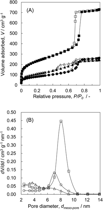
| KIT-6 (K) | 840 | 1.13 | 1.02 | 8.1 |
| Z20N/S(600) | 19 | 0.10 | 0.11 | >50 |
| Z20N/K(600) | 567 | 0.85 | 0.82 | 8.2 |
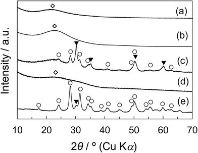
Fig. 1 shows the XRD patterns of non-porous and porous silica samples and their composite samples with zirconia. The diffraction pattern of the commercial zirconia, JRC-ZRO-3 (Japan Reference Catalyst, Catalysis Society of Japan) used as the reference zirconia was also shown. The crystalline phase of zirconia at 600 °C is generally known to be the mixture of metastable tetragonal and monoclinic phases. Indeed, JRC-ZRO-3 primarily exhibited the monoclinic phase and partially tetragonal phase, as shown in Fig. 1e. For the Z20N/S(600), the diffraction peaks corresponding to tetragonal and monoclinic phases were observed (Fig. 1c). On the other hand, as shown in Fig. 1d, the only broad diffraction peak attributed to KIT-6 was observed for Z20N/K(600), indicating that zirconia is either in amorphous state or consists of microcrystal particles. We consider that the existence of meso-pore in the silica significantly affects the difference in the crystallization behavior of zirconium component to zirconia.
| Sample | SBETa/m2 g−1 | Vporeb/cm3 g−1 | Vmeso-porec/cm3 g−1 | dmeso-pored/nm | ZrO2/(ZrO2 + SiO2)e/wt% |
|---|---|---|---|---|---|
| a BET specific surface area.b Total pore volume: estimated at 0.99P/P0.c Pore volume of meso-pores: estimated by the BJH method.d Major meso-pore diameter peaks: estimated from adsorption branch by the BJH method.e Weight ratio: estimated by the ICP-AES analysis. | |||||
| Z50P/K(600) | 392 | 0.38 | 0.32 | 3.7, 7.1 | 57 |
| Z50N/K(600) | 295 | 0.41 | 0.38 | 7.1 | 45 |
| rZP(600) | <1 | 0.02 | 0.02 | >50 | 100 |
| rZN(600) | 32 | 0.26 | 0.26 | >50 | 100 |
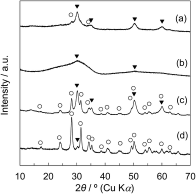
The XRD patterns of Z50P/K(600), Z50N/K(600), rZP(600), and rZN(600) are shown in Fig. 3. It was observed that the zirconia samples synthesized by the thermal decomposition method from zirconium propoxide and zirconyl nitrate as zirconium sources consist of monoclinic and tetragonal phases. For the rZN(600), the diffraction peaks assigned to the tetragonal phase were observed slightly and the peaks assigned to monoclinic phase were mainly observed. For the Z50P/K(600), the formation of zirconia with monoclinic and tetragonal phases were confirmed, while tetragonal phase was found to be the main crystalline phase. In contrast, the broad diffraction peaks appeared at 2θ = ca. 30° and ca. 50° for the Z50N/K(600). It is presumably considered that the zirconia components are mainly amorphous and slightly tetragonal. These results revealed that the crystal growth behavior of zirconia differs depending on the zirconium source. The crystalline phase of Z50N/K(600) was solely tetragonal and because of this the zirconia crystal can be formed in the meso-porous space of KIT-6. The pore size of KIT-6 was ca. 8.1 nm, and thus, the space in which zirconia crystal can be grown is limited from reaching the meso size. Garvie et al. reported that when the zirconia particle size is below 30 nm, the zirconia after the calcination below 1170 °C can be theoretically found in the tetragonal phase.3,4 As in the present case, tetragonal zirconia is considered to be predominantly formed because the crystal growth of zirconia particles was limited below 30 nm.
![[3 with combining macron]](https://www.rsc.org/images/entities/char_0033_0304.gif) d structure of KIT-6 was retained after the calcination at 800 °C. Therefore, for the synthesis of the ZrO2/SiO2 composites, while SBET, Vpore, Vmeso-pore, and dmeso-pore are decreased to a certain extent, the mesoporous structure of KIT-6 is considered to be maintained after the high temperature calcination at 800 °C.
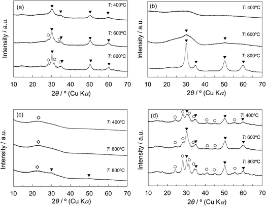
d structure of KIT-6 was retained after the calcination at 800 °C. Therefore, for the synthesis of the ZrO2/SiO2 composites, while SBET, Vpore, Vmeso-pore, and dmeso-pore are decreased to a certain extent, the mesoporous structure of KIT-6 is considered to be maintained after the high temperature calcination at 800 °C.The ZrO2/SiO2 composites were synthesized from KIT-6 and from zirconium propoxide or zirconium nitrate as zirconia sources by the 50 wt% of the introduced amount, followed by the final calcination at 400 °C, 600 °C, and 800 °C (denoted as Z50P/K(T) and Z50N/K(T)). The physical properties of the synthesized composites are summarized in Table 3. As mentioned above, the ZrO2/SiO2 composites (Z50P/K(T)) synthesized from zirconium propoxide with various calcination temperatures showed two mesopore peaks in each BJH plot. The SBET, Vpore, and Vmeso-pore of Z50P/K(T) decreased with increasing calcination temperature. This may be due to the shrinkage of KIT-6 and the grain growth of zirconia. In contrast, for the ZrO2/SiO2 composites (Z50N/K(T)) synthesized from zirconium nitrate at 400 °C, 600 °C, and 800 °C, their dmeso-pore were 8.2 nm, 7.1 nm, and 7.2 nm, respectively. As discussed in the above section, the crystal growth behavior of zirconia in KIT-6 is considered to be influenced by the zirconia source and the used solvent.
| Sample | SBETa/m2 g−1 | Vporeb/cm3 g−1 | Vmeso-porec/cm3 g−1 | dmeso-pored/nm | ZrO2/(ZrO2 + SiO2)e/wt% |
|---|---|---|---|---|---|
| a BET specific surface area.b Total pore volume: estimated at 0.99P/P0.c Pore volume of meso-pore: estimated by the BJH method.d Major meso-pore diameter peaks: estimated from adsorption branch by the BJH method.e Weight ratio: estimated by the ICP-AES analysis. | |||||
| Z50P/K(400) | 492 | 0.46 | 0.38 | 3.7, 7.2 | 57 |
| Z50P/K(600) | 392 | 0.38 | 0.32 | 3.7, 7.2 | 57 |
| Z50P/K(800) | 260 | 0.30 | 0.27 | 3.7, 6.3 | 58 |
| Z50N/K(400) | 407 | 0.53 | 0.44 | 8.2 | 48 |
| Z50N/K(600) | 295 | 0.41 | 0.38 | 7.1 | 45 |
| Z50N/K(800) | 299 | 0.40 | 0.38 | 7.2 | 47 |
| Z20N/K(400) | 589 | 0.88 | 0.81 | 8.2 | 21 |
| Z20N/K(600) | 567 | 0.85 | 0.79 | 8.2 | 21 |
| Z20N/K(800) | 458 | 0.70 | 0.67 | 7.2 | 22 |
| Z80N/K(400) | 240 | 0.49 | 0.49 | 4.8, 9.2 | 85 |
| Z80N/K(600) | 226 | 0.41 | 0.41 | 4.8, 8.1 | 83 |
| Z80N/K(800) | 221 | 0.32 | 0.32 | 4.2, 6.2 | 83 |
Fig. 4a and b show the XRD patterns of Z50P/K(T) and Z50N/K(T) with various calcination temperatures. For the Z50P/K(400), only the peaks corresponding to the tetragonal phase of zirconia appeared, whereas for the Z50P/K(600 and 800), the diffraction peaks assigned to monoclinic phase were also observed. The rZP(600) synthesized by the thermal decomposition method was composed of monoclinic and tetragonal phases as shown in Fig. 3c, indicating that the crystallization of the zirconium component outside the mesoporous space of KIT-6 results in the formation of the mixed crystal zirconia. Therefore, a part of zirconia was considered to be crystallized on the outside of the mesoporous space of the silica for the Z50P/K(600 and 800). However, it is important to note that the crystallization behavior of zirconia for the Z50N/K(T) was quite unique in comparison to the cases for the other samples. As shown in Fig. 4b, the broad peak was observed at 2θ = ca. 30° for the Z50N/K(400) for the final calcination at 400 °C, implying that the zirconia was in the amorphous state. With increasing calcination temperature, the peak attributed to the tetragonal phase gradually appeared, and it was observed that the Z50N/K(800) consisted of only tetragonal zirconia even after the final calcination at 800 °C.
| Sample | SBETa/m2 g−1 | Vporeb/cm3 g−1 | Vmeso-porec/cm3 g−1 | dmeso-pored/nm | ZrO2/(ZrO2 + SiO2)e/wt% |
|---|---|---|---|---|---|
| a BET specific surface area.b Total pore volume: estimated at 0.99P/P0.c Pore volume of meso-pores: estimated by the BJH method.d Major meso-pore diameter peaks: estimated from adsorption branch by the BJH method.e Weight ratio: estimated by the ICP-AES analysis. | |||||
| Q-3 | 725 | 0.45 | 0.26 | <2 | — |
| Q-10 | 315 | 1.35 | 1.33 | 7.1, 12.1, 16.0, 21.3 | — |
| Q-30 | 115 | 1.33 | 1.32 | 59.0 | — |
| Q-50 | 73 | 1.16 | 1.16 | 78.0 | — |
| Z20N/Q-3 | 352 | 0.23 | 0.16 | <2 | 21 |
| Z20N/Q-10 | 253 | 0.93 | 0.92 | 8.1, 12.1, 16.0, 24.5 | 22 |
| Z20N/Q-30 | 115 | 1.00 | 0.99 | 51.0 | 22 |
| Z20N/Q-50 | 82 | 0.87 | 0.87 | 78.0 | 21 |
| Z50N/Q-3 | 298 | 0.25 | 0.21 | <2 | 57 |
| Z50N/Q-10 | 215 | 0.57 | 0.56 | 6.2, 10.6 | 55 |
| Z50N/Q-30 | 109 | 0.59 | 0.59 | 10.6, 13.9, 44.1 | 55 |
| Z50N/Q-50 | 77 | 0.51 | 0.51 | 21.3 | 55 |
For the Z20N/Q-M (M = 3, 10, 30) composites, the SiO2 and tetragonal zirconia phases were observed, while a small amount of the monoclinic phase was also present for the Z20N/Q-50 composite (Fig. S4a†). Furthermore, the Z50N/Q-M (M = 3, 10, 30, 50) composites consisted of monoclinic and tetragonal phases (Fig. S4b†). Additionally, we found that the fraction of the tetragonal phase was decreased with increasing Q-M pore size. Furthermore, the crystallinity of the zirconia component in each composite was higher compared to the case using the synthesized KIT-6, K(600), shown in Fig. 4b and c. Based on these results, we conclude that the pore size of the silica template affects the synthesis process of zirconia more significantly than the Zr–O–Si linkages effect. Namely, an increase in the pore size of the silica leads to the significant growth of zirconia particles, resulting in the formation of the monoclinic phase.
Removal of silica component
The pure zirconia samples with the removal of the silica component, tZN(T), were synthesized by the alkaline treatment of Z50N/K(T) using the KOH solution. When a similar treatment was conducted for the rZN(600) zirconia samples synthesized by the thermal decomposition method, there were no changes of the crystalline phase, SBET, Vpore, Vmeso-pore, and dmeso-pore, implying that the KOH solution cannot dissolve the zirconia. The physical properties of tZN(T) and rZN(T) with the calcination temperatures of 400 °C, 600 °C, and 800 °C (T) based on the N2 ad–desorption, ICP-AES, and XRD analyses are summarized in Table 5. It was found that ca. 10 wt% of the KIT-6 silica component remained in the tZN(T) according to the results of the ICP-AES analysis. Upon increasing the calcination temperature, the SBET of each zirconia was increased. We note that tZN(T) exhibited much larger SBET values than those of rZN(T); the SBET of tZN(800) was 185 m2 g−1, while the SBET of rZN(800) was 12 m2 g−1. By contrast, there were no distinct differences in the Vpore and Vmeso-pore between tZN(T) and rZN(T).| Sample | SBETa/m2 g−1 | Vporeb/cm3 g−1 | Vmeso-porec/cm3 g−1 | dmeso-pored/nm | ZrO2/(ZrO2 + SiO2)e/wt% | Crystallite size of ZrO2 (h k l)-phasef/nm |
|---|---|---|---|---|---|---|
| a BET specific surface area.b Total pore volume: estimated at 0.99P/P0.c Pore volume of meso-pores: estimated by the BJH method.d Major meso-pore diameter peaks: estimated from adsorption branch by the BJH method.e Weight ratio: estimated by the ICP-AES analysis.f M: monoclinic, T: tetragonal.g Not detected the clear diffraction peak. | ||||||
| tZN(400) | 301 | 0.22 | 0.16 | <2 | 89 | n.d.g |
| tZN(600) | 260 | 0.23 | 0.19 | <2 | 90 | n.d.g |
| tZN(800) | 185 | 0.19 | 0.17 | <2 | 95 | 6.3 (1 0 1)-T |
| rZN(400) | 82 | 0.26 | 0.26 | 5, 14 | 100 | 6.6 (−1 1 1)-M, 12.0 (1 0 1)-T |
| rZN(600) | 32 | 0.26 | 0.26 | 4, 21, 33 | 100 | 15.2 (−1 1 1)-M, 17.4 (1 0 1)-T |
| rZN(800) | 12 | 0.18 | 0.18 | 4, 24, 44 | 100 | 29.6 (−1 1 1)-M |
The XRD patterns of tZN(T) and rZN(T) with the calcination temperatures of 400 °C, 600 °C, and 800 °C are displayed in Fig. 5. For the tZN(T) samples, the broad diffraction peak assigned to amorphous zirconia was observed for the tZN(400) and tZN(600); tZN(600) possessed tetragonal phase slightly. This was similar to the observations for Z50N/K(400) and Z50N/K(600). For tZN(800), the diffraction peaks attributed to the tetragonal phase became sharper; however, the monoclinic zirconia phase was not observed. Conversely, the rZN(400) and rZN(600) were mixed crystals of tetragonal and monoclinic zirconia, and the rZN(800) was pure monoclinic zirconia. The crystallite sizes of each ZrO2 phase determined using Scherrer's equation are summarized in Table 5. For the rZN(T) with the calcination temperatures of 400 °C, 600 °C, and 800 °C, the crystallite sizes of the (111) plane of monoclinic zirconia appearing ca. 28.2° were 6.6 nm, 15.2 nm, and 29.6 nm, respectively. Furthermore, for the rZN(T) with the T of 400 °C and 600 °C, the crystallite sizes of the (101) plane of tetragonal zirconia appearing ca. 30.5° were 12.0 nm and 17.4 nm, respectively. By contrast, for the rZN(T), the crystallite size of the (101) tetragonal phase, which can be identified only for the tZN(800), was 6.3 nm.
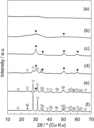 | ||
| Fig. 5 Wide-angle XRD patterns of (a) tZN(400), (b) tZN(600), (c) tZN(800), (d) rZN(400), (e) rZN(600), and (f) rZN(800): (○) ZrO2-monoclinic, (▼) ZrO2-tetragonal. | ||
Fig. 6 shows the Raman spectra of tZN(T) and rZN(T) with the T of 400 °C, 600 °C, and 800 °C and reference zirconia (JRC-ZRO-3). In the case of tZN(T), large differences were present in the obtained Raman spectra. For the tZN(400) and tZN(600), no remarkable band peaks appeared, implying that they were almost in the amorphous state (Fig. 6a and b). By contrast, the tZN(800) exhibited distinctive spectra derived from tetragonal zirconia (Fig. 6c).37,38 Considering the XRD analysis, we conclude that the tZN(800) certainly consists of tetragonal zirconia. In addition, for the rZN(400) and rZN(600), the band peaks attributed to monoclinic and tetragonal zirconia were observed (Fig. 6d and e). In contrast, the band peaks assigned to only monoclinic zirconia were observed for the rZN(800) and the reference zirconia (Fig. 6f and g). These results indicate that the rZN(400) and rZN(600) were mixed crystals of tetragonal and monoclinic zirconia and the rZN(800) and reference zirconia consist of monoclinic zirconia, supporting the results of XRD analysis.
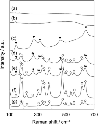 | ||
| Fig. 6 Raman spectra of (a) tZN(400), (b) tZN(600), (c) tZN(800), (d) rZN(400), (e) rZN(600), (f) rZN(800), and (g) reference ZrO2 (JRC-ZRO-3): (○) ZrO2-monoclinic, (▼) ZrO2-tetragonal. | ||
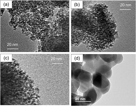
Fig. 7 represents the TEM images of tZN(T) (T = 400, 600, 800) and rZN(600) samples. From these TEM images, the average sizes of zirconia particles were found to be ca. 23 nm for the rZN(600) and 2.0 nm, 2.2 nm, and 4.5 nm for the tZN(400), tZN(600) tZN(800), respectively. Upon increasing the calcination temperature, the synthesized zirconia particles were enlarged. However, it is noteworthy that the particle growth of the zirconia was apparently suppressed for the synthesis using meso-porous silica in comparison to the case for the synthesis by the thermal decomposition method.
As mentioned in Introduction section, monoclinic zirconia is considered to be stable up to 1170 °C. In addition, the theoretical study proves that a metastable tetragonal zirconia can be stable below 650 °C if the zirconia particle size is below 30 nm.3,4 Furthermore, it was reported that tetragonal zirconia can be synthesized using some special synthesis techniques.6–26 In contrast, the synthesis method reported in the present work, is a new method of the nanosized tetragonal zirconia from KIT-6 or commercial silica and from zirconyl nitrate without the high pressure synthesis conditions and special precipitating agents. Furthermore, the synthesized tetragonal zirconia possesses large specific surface area even after the final calcination at 800 °C.
Evaluation of catalytic activity for MeOH oxidation
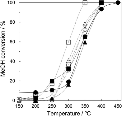
Finally, the synthesized tZN(T) have been used as a catalyst for MeOH oxidation. Fig. 8 shows the temperature dependence of MeOH conversion for MeOH oxidation over the tZN(T) catalysts that possess only tetragonal phase, and rZN(T) and JRC-ZRO-3 as reference catalysts that possess monoclinic and tetragonal phases. In the present work, the main reaction products were CO and H2O for the MeOH oxidation over all catalysts. We confirmed that MeOH can be oxidized to CO2 and H2O using 2 wt% Ag catalysts supported by the synthesized zirconia (results are not shown). The addition of Ag component enhances the oxidation step of methoxy species to CO2 due to the formation of active oxygen species on Ag species.32 In addition, in situ Fourier Transform Infrared Spectroscopy (FTIR) demonstrates that the MeOH adsorption sites are on the zirconia support with high crystallinity. Therefore, to elucidate the adsorption property of MeOH on the synthesized zirconia, we have evaluated the catalytic property of zirconia for MeOH oxidation. Comparing the MeOH conversion at 300 °C, the performance order of the rZN(T) catalysts was as follows: rZN(800) > rZN(600) > rZN(400). Among the tZN(T) catalysts, tZN(800) exhibited the highest performance and the MeOH conversion at 300 °C was ca. 60%. The MeOH conversions over tZN(400) and tZN(600) were ca. 40%. The tZN(T) catalysts exhibited higher performance than rZN(T) catalysts and JRC-ZRO-3. This performance may be attributable to the larger surface area of tZN(T) than rZN(T). Additionally, we found that the higher the calcination temperature, the higher the catalytic performance of zirconia. Indeed, the MeOH conversion per the surface area for the zirconia catalysts was not constant, indicating that the crystallinity of zirconia affects the catalytic performance. In other words, an increase in the crystallinity of zirconia leads to the improvement of the dissociative adsorption performance of oxygen and the enhancement of the formation of active oxygen species on the zirconia surface, resulting in the high performance of zirconia for MeOH oxidation.In the present work, the tZN(800) which consists of fine particles, possesses high specific surface area, and has only tetragonal phase was successfully synthesized. In addition, it was revealed that the tZN(800) exhibits excellent catalytic performance for MeOH oxidation compared to the conventional zirconium catalysts. Furthermore, we suggest that application of a tetragonal zirconia material with large surface area as a catalyst will be beneficial for various catalytic processes such as water-gas-shift reaction, CO2 methanation, and MeOH synthesis.
Conclusions
Synthesis of zirconia by the hard template method using KIT-6 mesoporous silica and the performance of such zirconia for catalytic combustion have been studied. Composites of tetragonal zirconia and silica were successfully synthesized by the decomposition of zirconia sources in the mesoporous space of KIT-6. The formation behavior of tetragonal zirconia depends on the zirconia sources, the pore size of mesoporous silica, the loading amount of zirconia sources, and calcination temperature. The crystallization of zirconia in the mesoporous space results in the formation of fine zirconia particles, leading to the formation of pure tetragonal zirconia crystalline phase instead of the monoclinic zirconia crystalline phase, as known to occur due to the crystallite size effect. Furthermore, the nanosized tetragonal zirconia possessing large BET specific surface was synthesized through the removal of the silica component in the zirconia–silica composite by the alkaline treatment. In addition, the catalytic performance of tetragonal zirconia materials for methanol oxidative decomposition have been evaluated. Among the zirconia catalysts prepared in the present study, the sample prepared by the hard template method and calcined at 800 °C exhibited the highest activity for MeOH oxidation. We conclude that the crystallinity of zirconia and a high BET specific surface area are both necessary to achieve a high catalytic activity for the MeOH oxidation reaction.Conflicts of interest
There are no conflicts to declare.Acknowledgements
This study was supported by the Cooperative Research Program of Institute for Catalysis, Hokkaido University, (Grant #14B1009) and the authors would like to thank them for their support. Additionally, we are grateful to Prof. Koichi Eguchi, Kyoto University for their kind help with Raman spectroscopy analysis.Notes and references
- T. Yamaguchi, Catal. Today, 1994, 20, 199–218 CrossRef CAS.
- G. Štefanić, S. Musić and A. Sekulić, Thermochim. Acta, 1996, 273, 119–133 CrossRef.
- R. C. Garvie, J. Phys. Chem., 1965, 69(4), 1238–1243 CrossRef CAS.
- R. C. Garvie, J. Phys. Chem., 1978, 82(2), 218–224 CrossRef CAS.
- G. S. A. M. Theunissen, J. S. Bouma, A. J. A. Winnubst and A. J. Burggraaf, J. Mater. Sci., 1992, 27, 4429–4438 CrossRef CAS.
- W. Stichert and F. Schüth, Chem. Mater., 1998, 10, 2020–2026 CrossRef CAS.
- M. Inoue, H. Kominami and T. Inui, Appl. Catal., A, 1993, 97, L25–L30 CrossRef CAS.
- H. S. Kil, S. H. Hwag, J. H. Ryu, D. Y. Lim and S. B. Cho, J. Ceram. Soc. Jpn., 2012, 120, 52–57 CrossRef CAS.
- S. Riaz, M. Bashir and S. Naseem, J. Sol-Gel Sci. Technol., 2015, 74, 275–280 CrossRef CAS.
- Y. Chang, C. Wang, T. Liang, C. Zhao, X. Luo, T. Guo, J. H. Gong and H. Wu, RSC Adv., 2015, 5, 104629–104634 RSC.
- Q. W. Ge, X. P. Liu, G. Parada, S. K. Mallapragada and M. Akinc, Sci. Adv. Mater., 2014, 6, 2106–2114 CrossRef CAS.
- Q. Mahmood, A. Afzal, H. M. Siddiqi and A. Habib, J. Sol-Gel Sci. Technol., 2013, 67, 670–674 CrossRef CAS.
- F. Davar, A. Hassankhani and M. R. Loghman-Estarki, Ceram. Int., 2013, 39, 2933–2941 CrossRef CAS.
- N. B. Nayak, B. B. Nayak and A. Mondal, J. Am. Ceram. Soc., 2013, 96, 3366–3368 CrossRef CAS.
- M. C. Wang and H. J. Huang, Thermochim. Acta, 2013, 567, 93–99 CrossRef CAS.
- A. U. Maheswari, S. S. Kumar and M. Sivakumar, J. Nanosci. Nanotechnol., 2013, 13, 4409–4414 CrossRef CAS PubMed.
- V. G. Deshmane and Y. G. Adewuyi, Microporous Mesoporous Mater., 2012, 148, 88–100 CrossRef CAS.
- H. Saricimen, A. Ul-Hamid and A. Quddus, Prot. Met. Phys. Chem. Surf., 2015, 51, 803–811 CrossRef CAS.
- M. Salavati-Niasari, M. Dadkhah, M. R. Nourani and A. A. Fazl, J. Cluster Sci., 2012, 23, 1011–1017 CrossRef CAS.
- X. L. Yan, N. Y. Lu, B. B. Fan, J. H. Bao, D. H. Pan, M. J. Wang and R. F. Li, CrystEngComm, 2015, 17, 6426–6433 RSC.
- P. Wang, Z. D. Zhao, Z. D. Zhao, Z. D. Wang, S. X. Chen and G. R. Fan, BioResources, 2015, 10, 1271–1284 Search PubMed.
- L. Liu, J. C. Xue and X. P. Zhou, Nanosci. Nanotechnol. Lett., 2014, 6, 346–352 CrossRef CAS.
- S. Kurakaran, A. George and A. S. Nair, J. Indian Chem. Soc., 2014, 91, 47–52 CAS.
- C. Sanchez, C. Boissire, D. Grosso, C. Laberty and L. Nicole, Chem. Mater., 2008, 20, 682–737 CrossRef CAS.
- J. N. Kondo and K. Domen, Chem. Mater., 2008, 20, 835–847 CrossRef CAS.
- R. Xu, W. Pang, J. Yu, Q. Huo and J. Chen, Chemistry of Zeolites and Related Porous Materials – Synthesis and Structure, John Wiley & Sons (Asia) Pte., 2007 Search PubMed.
- F. Kleitz, S. H. Choi and R. Ryoo, Chem. Commun., 2003, 2136–2137 RSC.
- B. Liu and R. T. Baker, J. Mater. Chem., 2008, 18, 5200–5207 RSC.
- N. Suzuki, T. Kimura and Y. Yamauchi, J. Mater. Chem., 2010, 20, 5294–5300 RSC.
- Q. Pan, A. Ramanathan, W. K. Snavely, R. V. Chaudhari and B. Subramaniam, Ind. Eng. Chem. Res., 2013, 52, 15481–15487 CrossRef CAS.
- L. Gong, L. B. Sun, Y.H Sun, T. T. Li and X. Q. Liu, J. Phys. Chem. C, 2011, 115, 11633–11640 CAS.
- N. Shimoda, S. Umehara, M. Kasahara, T. Hongo, A. Yamazaki and S. Satokawa, Appl. Catal., A, 2015, 507, 56–64 CrossRef CAS.
- I. Ro, Y. Liu, M. R. Ball, D. H. K. Jackson, J. P. Chada, C. Sener, T. F. Kuech, R. J. Madon, G. W. Huber and J. A. Dumesic, ACS Catal., 2016, 6, 7040–7060 CrossRef CAS.
- T. Witoon, J. Chalorngtham, P. Dumrongbunditkul, M. Chareonpanich and J. Limtrakul, Chem. Eng. J., 2016, 293, 327–336 CrossRef CAS.
- S. Tada, F. Watanabe, K. Kiyota, N. Shimoda, R. Hayashi, M. Takahashi, A. Nariyuki, A. Igarashi and S. Satokawa, J. Catal., 2017, 351, 107–118 CrossRef CAS.
- Y. Azuma, K. Nogami and N. Ohshima, J. Ceram. Soc. Jpn., 1992, 100, 646–651 CrossRef CAS.
- J. A. Muñoz Tabares and M. J. Anglada, J. Am. Ceram. Soc., 2010, 93, 1790–1795 Search PubMed.
- S. Pradhan, V. Sahu and B. G. Mishra, J. Mol. Catal. A: Chem., 2016, 425, 297–309 CrossRef CAS.
Footnote |
| † Electronic supplementary information (ESI) available. See DOI: 10.1039/c7ra10942c |
| This journal is © The Royal Society of Chemistry 2017 |


