 Open Access Article
Creative Commons Attribution 3.0 Unported Licence
A low-loss electromagnetically induced transparency (EIT) metamaterial based on coupling between electric and toroidal dipoles
Lei Zhu *ab,
Liang Dongac,
Jing Guod,
Fan-Yi Menge,
Xun Jun He
 f,
Chun Hui Zhaob and
Qun Wue
aCommunication and Electronics Engineering Institute, Qiqihar University, Qiqihar, 161006, China. E-mail: zhuzhubutterfly@163.com
bCollege of Information and Communication Engineering, Harbin Engineering University, Harbin, 150001, China
cSchool of Electronic Engineering, Beijing University of Posts and Telecommunications, Beijing, 100876, China
dScience and Technology on Electronic Test & Measurement Laboratory, Ministry of Education, North University of China, Taiyuan, 030051, China
eElectronics and Information Institute, Harbin Institute of Technology, Harbin, 150001, China
fDepartment of Electronic Science and Technology, Harbin University of Science and Technology, Harbin, 150080, China
First published on 11th December 2017
Abstract
Herein, an effective approach to construct a low-loss metamaterial by incorporating an electric toroidal dipole response into electromagnetically induced transparency (EIT) effect has been proposed, which is numerically and experimentally demonstrated. The low-loss metamaterial consists of an I-type cut wire (ICW) and two spiral ring resonators (SRRs). It is numerically verified that the low-loss electric toroidal dipole resonance can be excited by rational rotation of SRR, accompanied by a circumfluent magnetic field distribution. Via subtle geometry adjustment, we realized the spectral overlap of electric and toroidal dipoles and then observed a low-loss EIT resonance based on destructive couplings between them. In addition, the effect of parametric variation for the metamaterial on EIT resonance is investigated. In particular, we have experimentally verified that low-loss EIT resonance is also obtained by altering the rotation axis of two SRRs. By scaling down our structure, our design also applies to higher frequencies. This low-loss scheme provides possibilities for the design of low-loss optical devices and highly sensitive sensors.
1. Introduction
Metamaterials exhibit several unusual electromagnetic (EM) properties1 owing to the flexibility of design of its constituent elements.2 The artificial EM material allows the realization of a plethora of EM phenomena such as invisibility cloak,3 electromagnetically induced transparency (EIT),4–7 and chirality,8 which are unattainable using natural materials.9 Although metamaterials exhibit these important EM properties, their performance is limited by the occurrence of losses.10 Specially, when the losses become very large, metamaterials and the relevant devices cannot even work.Metamaterial losses consist of two parts: radiation and dissipation losses.11 Dissipation loss can be minimized using a good conductor or dielectric material, whereas primary radiation loss can be reduced using destructive interference between bright and dark resonances,12–14 known as Fano resonances or EIT effects.12–14 Generally, the electric dipole response serves as a bright resonance, and the magnetic dipole or quadrupole response serves as a dark resonance. However, the toroidal dipole as a third family multipole is usually ignored.15–21 This is because its EM properties are often covered by much stronger electric and magnetic resonances.15–21 Zheludev et al. first experimentally demonstrated the toroidal dipolar response22 and pointed out that it might be considered as circular head-to-tail magnetic dipoles of SRR arrangement.22 Many similar toroidal metamaterials have been reported.15–25 A large number of exotic EM phenomena in toroidal metamaterials have also been verified such as polarization conversion,20 optical activity, and EITs.17,20,21 More importantly, metamaterials with toroidal dipolar response couple weakly EM waves;23,25 thus, their scattering loss is very low. Therefore, combining EIT resonance with toroidal dipolar response will minimize the radiation loss of metamaterials. As reported in literature,17,20,25 the toroidal dipolar response interaction with other elementary multipoles17,20,25 can result in EIT resonance.26–28
Compared with EIT metamaterials with toroidal dipole response, reported in ref. 16, 17, 21 and 28, metamaterials are three-dimensional and inconvenient to process and fabricate; hence, we propose a planar structure to achieve the electric toroidal dipolar resonance. This planar structure consists of an I-type cut wire (ICW) and two rotated spiral ring resonators (SRRs). While the low-loss electric toroidal dipole effect15–25 can be excited in planar metamaterials, low-loss EIT resonance can also be achieved in metamaterials based on destructive coupling between electric and toroidal dipoles.17,20,25 Owing to these effects, the total radiation losses of metamaterials are reduced, transmission is enhanced, and the low-loss EIT metamaterial is achieved. It is worth noting that in our study, we focus on the idea of combining EIT with the toroidal dipoles. Thus, the low-loss property in our structure stems from the collective action of EIT resonance and electric toroidal dipole response. In addition, our designed structure is two-dimensional and refers only to a single-layer metal surface, which is easily fabricated by utilizing the printed circuit board (PCB) technology.20,23,25,26 Moreover, the transverse electric size of our structure is smaller (∼0.28 λ × 0.16 λ) and its thickness is lower (∼0.018 λ) as compared to that of the structure reported in ref. 25 (0.43 λ × 0.43 λ × 0.027 λ). Therefore, our scheme is more miniaturized, and it is more convenient for integration with existing microwave or photonic circuits.
2. Structure design
As shown in Fig. 1(a), the unit cell of the EIT metamaterial is composed of two SRRs25 and an ICW resonator. The two SRRs have a 180° rotational symmetry about the x-axis, and they are placed on the longer arm of the ICW. The two SRRs and ICW are made of copper with a thickness of 0.035 mm and an electric conductivity26,27 of σ = 5.96 × 10⁷ S m−1. These metal patterns are fabricated on an FR4 substrate with a permittivity of 4.3, loss tangent of 0.005, and thickness of 1 mm. The geometrical parameters of the structure in Fig. 1(a) are designed as a = 16 mm, b = 9.2 mm, l1 = 13.2 mm, l2 = 4 mm, l3 = 3.5 mm, l4 = 2.8 mm, l5 = 1.65 mm, l6 = 2.6 mm, l7 = 1.2 mm, and s1 = s2 = 0.425 mm. Fig. 1(b) shows a part of the sample image. The metamaterial sample was fabricated by utilizing traditional PCB technology.26 The sample size is 352 mm × 352 mm, including 22 × 38 unit cells. The free-space test method27 was utilized to obtain transmission spectra of the sample. We performed measurement experiments in an anechoic chamber, where two standard horn antennas27 and an Agilent 8510B vector network analyzer (VNA) were used.27 In our simulation, CST Microwave Studio software was used.27 Plane waves are incident perpendicular to the metamaterial surface,26 with the E-field polarized along the x-axis and H-field polarized along the y-axis.3. Results and analyses
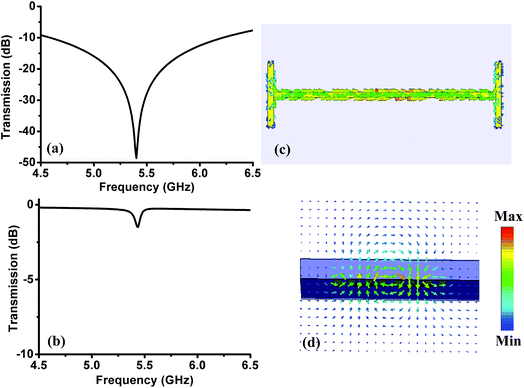
We first discussed the transmission responses of independent SRRs and ICW resonators and then analyzed their resonance mechanism. Fig. 2(a) and (b) display the transmission spectra of the independent SRRs and ICW resonators, respectively. As shown in Fig. 2(a), for the excitation of incident waves with the E-field polarized along the x-axis,27 the independent ICW shows a strong resonance at 5.41 GHz with a quality factor (Q factor) of 1.2. This resonance mode can be directly excited by the E-field of the incoming waves.25 This is because the E-field component of the incoming waves is parallel to the longer arm of ICW, and the surface currents excited by the E-field flow along the longer arm of the ICW, as shown in Fig. 2(c). Thus, the resonance property of the ICW belongs to the electric dipole resonance.15–25On the other hand, for excitation of incident waves with the E-field polarized along x-axis, the two SRRs show a toroidal dipolar resonance15–25 at 5.41 GHz with a Q factor of 60.3, as displayed in Fig. 2(b). As the H-field component of incident waves is parallel to the SRRs, the toroidal dipolar resonance in SRRs cannot be excited by the H-field.20–25 Thus, this resonance response belongs to electric toroidal dipolar resonance.20–25 This can be demonstrated by magnetic field and surface current distributions inside our structure, as shown in Fig. 2(d) and 3(a). For x-polarized incident waves, circular currents are excited in each SRR loops. Moreover, two circular currents induce the circulating magnetic moments m encircling the central part of the two SRR structure, as shown in Fig. 3(a). As a consequence, this causes a toroidal moment T along the x-axis. In this case, a head-to-tail magnetic dipole of circumfluent magnetic field15–25 distributes in two rotated SRRs, as shown in Fig. 2(d), which is a typical characteristic of toroidal dipoles.15–25 This field distribution suppresses the radiation in free space;15–25 thus, scattering loss of the metamaterial is decreased, and a high Q factor of resonance dip appears in the transmission spectrum. The orientation of the toroidal dipole moment is along the rotational x-axis, parallel to the exciting E-field; this further verifies its electric resonance origin.22,23,28 In addition, it is found that most electromagnetic energies concentrate in the dielectric substrate with toroidal geometry.15–25 As pointed out in ref. 15–20 and 22, this field distribution implies that losses in the metamaterial are greatly overcome. Thus, the proposed toroidal metamaterial convincingly exhibits the low-loss property for the toroidal mode.22–25
 | ||
| Fig. 3 (a) Surface current distribution of the two SRRs at 5.41 GHz, (b) surface current distribution of the EIT metamaterial at 5.41 GHz. | ||
To further verify the validity of the toroidal dipole response in the two SRR structures, we calculated the scattered powers for the three major multipoles: the electric dipole, the magnetic dipole, and the toroidal dipole, in arbitrary units according to the volume current density distribution in a unit cell.15–28 The calculated results are shown in Fig. 4. It can be seen from Fig. 4(a) that the traditional magnetic dipole moment M has been suppressed, whereas the toroidal dipole moment T plays a crucial role as compared to the electric and magnetic dipoles.15–28 In particular, the toroidal dipole moment T reaches its peak value at 5.41 GHz, whereas the electric dipole moment P reaches its dip value as well. At 5.41 GHz, the radiating power for the toroidal dipole moment is about 4 times larger than that for the electric dipole moment. As a consequence, in the two SRR structures, we obtained the toroidal dipole response.15–28 The toroidal dipolar excitation also manifests itself as a dip in the transmission spectra at 5.41 GHz, as shown in Fig. 2(b).
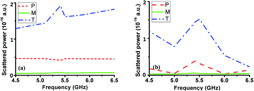 | ||
| Fig. 4 Scattered powers for multipole moments in a unit cell. (a) Two SRRs and (b) EIT metamaterial. | ||
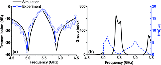
Based on the abovementioned analysis, we concluded that the two SRR structures with toroidal dipole response were responsible for the low loss property. As a result, to minimize the radiation loss of the metamaterial, the ICW resonator with electric dipole response is expected to introduce the toroidal geometry. Based on destructive coupling between scattering fields of electric and toroidal dipoles, a low-loss EIT metamaterial can be obtained. To achieve EIT resonance, resonators with similar resonance frequencies and different Q factors are necessary.12–14,28 In our configuration, by deliberately optimizing the parameters, the resonance responses of the SRRs and ICW resonators can satisfy the abovementioned conditions. As a consequence, SRRs with a high Q factor serve as the dark resonator,4–7,12–14 whereas an ICW with a low Q factor acts as a bright resonator.4–7,12–14 When we combined the SRRs and ICW resonators, forming the unit cell displayed in Fig. 1(a), an EIT window appeared in the transmission spectra because of the destructive coupling of scattering fields between them,4–7,12–14,17,25 as shown in Fig. 5(a). It is observed that the frequency of the EIT window is about 5.41 GHz, and its peak is about 0.8. Hence, the low-loss EIT effect is achieved. Simultaneously, it is also found that the measured transmission curves coincide with the simulation curves;27 this further demonstrates the validity of generation of low-loss EIT resonance.
To demonstrate slow light behavior with low loss in the EIT structure, the effective group index ng (ref. 4, 5 and 7) and the imaginary part of the effective refractive index Im(neff)4,5,7 are extracted from the S parameters, and the results are plotted in Fig. 5(b). It is seen that the ng value attains 647 in the transparency window, which indicates that the light velocity can be slowed down by a factor of 647,29,30 related to the strong phase dispersion of EIT resonance.4,5,7,29,30 The effective group index in our structure is much larger than the values reported in classical EIT schemes.6–8,11,25 Additionally, it is found that the Im(neff) is very small in the EIT window, i.e., the absorption loss is very low. These abovementioned characteristics prove that a low-loss EIT metamaterial has been realized, and their origin is based purely on destructive couplings between electric and toroidal dipoles.4–7,12–14,17,25
To illustrate the collective action of toroidal dipole response and EIT resonance in reducing losses in the metamaterial, we simulate surface current distributions at EIT resonance, as shown in Fig. 3(b). As shown in Fig. 3(b), for x-polarized incident waves, circular currents are excited in both SRRs. Moreover, two circular currents induce the circulating magnetic moments m across the SRR structures. As a consequence, this causes a toroidal moment T along the negative x-axis. In addition, the electric dipole moment P along the positive x-axis is excited. Hence, electric and toroidal dipoles undergo destructive coupling, and most currents are located in the low loss toroidal geometry.17,20 As a consequence, a low-loss metamaterial is obtained by exciting EIT resonance with toroidal response.
To further discuss the collective action of toroidal dipole response and EIT resonance toward reducing losses in the metamaterial, we calculated the scattering powers of three major multipoles for the EIT metamaterial with toroidal dipole response, as shown in Fig. 4(b). We found that the main contribution over the entire frequency band was provided by the excitation of toroidal and electric dipoles.15–25 In particular, the toroidal dipole moment T reaches a peak value at 5.41 GHz, whereas the electric dipole moment P reaches its peak value as well. This means that the toroidal and electric dipoles are collocated and coherently oscillate at the same frequency 5.41 GHz.17,20 Hence, the radiated electromagnetic fields of electric and toroidal dipoles interfere destructively and disappear outside the metamaterial.17,20 As a consequence, the losses of the metamaterial are suppressed, and a low loss metamaterial based on EIT resonance with toroidal dipole response is achieved.
Considering that the EIT effect plays a key role in reducing losses of the metamaterial, it is necessary to profoundly explore the physical origin of EIT generation. Thus, we plot the surface current distributions at resonance dips and peak, as shown in Fig. 6. It is clearly seen that the induced currents reveal different distribution characteristics. At the first resonance dip, the current flows of the bottom arm for SRRs and the longer arm of ICW are same, and more currents concentrate in the ICW resonator, as depicted in Fig. 6(a). At the second resonance dip, the current flows of the bottom arm for SRRs and the longer arm of ICW are opposite, and the currents are mostly located in the ICW resonator, as displayed in Fig. 6(c). At the resonance peak, most currents are located in the dark SRRs, whereas there is hardly any current appearing in the ICW, and the anti-parallel currents31 flow in each SRR and ICW. This current distribution behavior results from the destructive interference of EM fields between bright dipole and dark toroidal dipole modes.4–7,12–14,17,25 In addition, we notice that currents in two SRRs show anti-symmetry distribution characteristic.25,31 Hence, the net residual currents in both SRRs are very small. As a consequence, the overall radiation losses in the metamaterial are dramatically decreased,6,7,11,27–30 the transmission is enhanced,6,7,11,27–30 and the low-loss EIT resonance is obtained.6,7,17,25
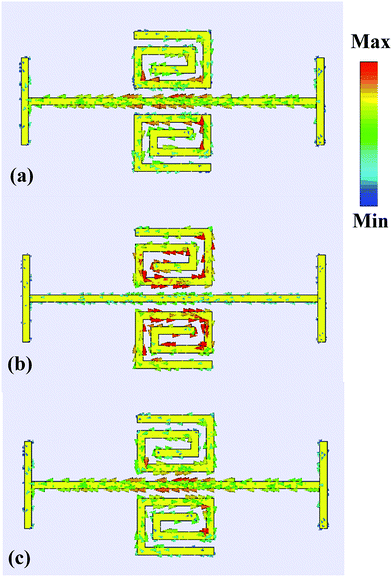 | ||
| Fig. 6 Surface current distributions of the EIT structure at the transmission resonances of (a) 5.01 GHz, (b) 5.41 GHz, and (c) 5.89 GHz. | ||
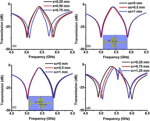
As previously discussed, the destructive coupling between electric and toroidal dipoles17,25 leads to low-loss EIT resonance.17,25 To explore the effect of destructive coupling6,7,17,25 on EIT resonance, the distance s between the SRRs and ICW resonators is changed from 0.25 mm to 0.75 mm (in this case, s1 = s2 = s), and the results are displayed in Fig. 7(a). It is observed that when the distance s decreases, the destructive coupling between the resonant elements6,7,11,27–30 gradually increases; this results in a more obvious EIT window. We also investigated the effect of the offset ss on the EIT resonance (the offset ss refers to separation of the two SRRs deviating from the center of ICW, as shown in the inset of Fig. 7(b)). As shown in Fig. 7(b), the EIT resonance is found to be hardly affected by the offset ss. A similar effect also appears in the transmission spectra when s3 is varied, as shown in Fig. 7(c). Herein, s3 is the offset between the two SRRs (inset of Fig. 7(c)). In addition, when s2 is kept constant and s1 is varied, the transparency window is split into two transmission peaks due to asymmetric couplings17,31 between the SRRs and ICW resonators. In other words, when s1 is varied, the ICW undergoes selective coupling17,31 with the two SRRs because of the asymmetric configuration;17,31,32 this results in a dual-band EIT effect, as shown in Fig. 7(d). Based on the abovementioned analysis, it is concluded that the transverse coupling separations ss and s3 between the SRRs and ICW have minor influences on EIT resonances, whereas the longitudinal coupling separations s1 and s2 between the SRRs and ICW have vital influences on EIT behaviors. A study of these parameters is very important for optimizing and designing an EIT metamaterial. For example, we may adjust the width and strength of the EIT window by changing the longitudinal spacing s.
In addition, we altered the rotated axis of the two SRRs (i.e. two SRRs are 180° rotational symmetry about y-axis); this formed a new structure, as shown in Fig. 8(a) and (b). In these figures, d1 = 0.3 mm, d2 = 0.4 mm, and the other parameters are same as shown in Fig. 1(a). In this new structure, the ICW resonator serves as a bright resonator,6,7,17,25 whereas the two SRRs serve as a dark resonator.6,7,17,25 Hence, destructive interferences between the bright dipolar mode16,17,21,25 induced by ICW and dark toroidal dipolar mode16,17,21,25 induced by two SRRs lead to a low loss EIT effect, as shown in Fig. 8(c). In this case, the transmission intensity is enhanced to more than 0.8, and measured results also demonstrate the low-loss EIT effect. Moreover, we extracted the effective group index4,5,7 and effective refractive index4,5,7 to verify the low-loss slow light behavior, as displayed in Fig. 8(d). As expected, in the transparency window, ng is increased to 973, and Im(neff) is very small. These phenomena further testify the low-loss EIT resonance observed from the transmission spectra,29,30 as shown in Fig. 8(c).
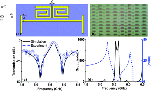 | ||
| Fig. 8 (a) Schematic of the new EIT structure; (b) sample image of the new EIT structure; (c) simulated and measured transmission curves; (d) ng and Im(neff). | ||
Finally, we also demonstrated the validity of our scheme at higher frequencies. We have scaled down our structure, and the corresponding results are displayed in Fig. 9. In this structure, the geometrical parameters are designed as a = 2000 nm, l1 = 1900 nm, l2 = 250 nm, l3 = 600 nm, l4 = 380 nm, l5 = 400 nm, l6 = 660 nm, l7 = 250 nm, and s1 = 86 nm. The two SRRs and cut wire are made of gold with a thickness of 100 nm.14 The width of all the gold wires is 100 nm. These gold patterns are fabricated on a substrate with a permittivity of 4.82, a loss tangent of 0.01, and a thickness of 200 nm. Similarly, a low loss transparency window with an amplitude of 0.7 appears at 36.2 THz owing to destructive interferences between bright dipolar mode induced by cut wire and dark toroidal dipolar mode induced by two SRRs. Specially, at the EIT peak resonance, a head-to-tail magnetic dipole of circumfluent magnetic field15–25 locates in the two rotated SRRs. These results verify that the low-loss property for our metamaterial results from collective action of EIT resonance and toroidal dipole response. As a consequence, our scheme can also be applied to higher frequencies.33,34
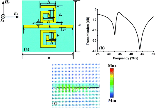 | ||
| Fig. 9 (a) EIT structure at higher frequencies, (b) transmission spectrum, (c) magnetic field distributions at transmission peak frequency. | ||
4. Conclusion
We numerically and experimentally verified that the destructive coupling between the electric dipoles and toroidal dipoles led to low-loss EIT effects in a metamaterial formed by an ICW and two SRRs, acting as bright and dark resonators, respectively. In essence, the low-loss property stems from the collective action of EIT resonance and electric toroidal dipole response. It is numerically shown that the electric toroidal dipole resonance with low loss can be obtained by rotating SRR reasonably. Specially, the destructive interferences between the electric dipole and toroidal dipole resonances result in a low-loss transparency window. The simulated imaginary parts of the effective refractive index, magnetic field distributions, and surface currents have also demonstrated the low-loss property of the metamaterial. Moreover, it is very interesting that the low-loss EIT resonance can be observed when the two SRRs are rotated about the y-axis; this is demonstrated via numerical simulation and experimental measurement. By scaling down our structure, our design can also apply to high frequencies.33,34 This low-loss scheme offers an opportunity for the design of low-loss optical devices and highly sensitive sensors.Conflicts of interest
There are no conflicts to declare.Acknowledgements
This work was supported by the National Natural Science Foundation of China (Grant No. 61501275, 61604133, and 51575149), the China Postdoctoral Science Foundation (Grant No. 2017M611357), the Science Foundation Project of Heilongjiang Province of China (Grant No. QC2015073), and the technology bureau of Qiqihar city of Heilongjiang Province of China (Grant No. GYGG-201511).References
- L. Zhou, X. Huang, Y. Zhang and S. T. Chui, Mater. Today, 2009, 12, 52–59 CrossRef.
- H. T. Chen, W. J. Padilla, J. M. Zide, S. R. Bank, A. C. Gossard, A. J. Taylor and R. D. Averitt, Opt. Lett., 2007, 32, 1620–1622 CrossRef CAS PubMed.
- Z. J. Wong, Y. Wang, K. O'Brien, J. Rho, X. Yin, S. Zhang and X. Zhang, J. Opt., 2017, 19, 084007 CrossRef.
- X. He, Y. Huang, X. Yang, L. Zhu, F. Wu and J. Jiang, RSC Adv., 2017, 7, 40321–40326 RSC.
- X. He, X. Yang, G. Lu, W. Yang, F. Wu, Z. Yu and J. Jiang, Carbon, 2017, 123, 668–675 CrossRef CAS.
- N. Papasimakis, V. A. Fedotov, N. I. Zheludev and S. L. Prosvirnin, Phys. Rev. Lett., 2008, 101, 253903 CrossRef CAS PubMed.
- P. Tassin, L. Zhang, T. Koschny, E. N. Economou and C. M. Soukoulis, Phys. Rev. Lett., 2009, 102, 053901 CrossRef CAS PubMed.
- S. Zhang, Y. S. Park, J. Li, X. Lu, W. Zhang and X. Zhang, Phys. Rev. Lett., 2009, 102, 023901 CrossRef PubMed.
- J. Hao, Q. Ren, Z. An, X. Huang, Z. Chen, M. Qiu and L. Zhou, Phys. Rev. A, 2009, 80, 023807 CrossRef.
- P. A. Belov and Y. Hao, Phys. Rev. B, 2006, 73, 113110 CrossRef.
- K. L. Tsakmakidis, M. S. Wartak, J. J. H. Cook, J. M. Hamm and O. Hess, Phys. Rev. B, 2010, 81, 195128 CrossRef.
- D. Wu, Y. Liu, L. Yu, Z. Yu, L. Chen, R. Li and H. Ye, Sci. Rep., 2017, 7, 45210 CrossRef CAS PubMed.
- L. Zhu, F. Y. Meng, J. H. Fu, Q. Wu and J. Hua, Opt. Express, 2012, 20, 4494–4502 CrossRef PubMed.
- N. Liu, L. Langguth, T. Weiss, J. Kästel, M. Fleischhauer, T. Pfau and H. Giessen, Nat. Mater., 2009, 8, 758–762 CrossRef CAS PubMed.
- M. Li, L. Guo, J. Dong and H. Yang, Appl. Phys. Express, 2014, 7, 082201 CrossRef.
- L. Guo, M. Li, H. Yang, X. Huang and S. Wu, J. Phys. D: Appl. Phys., 2014, 47, 415501 CrossRef.
- J. Li, Z. G. Dong, M. J. Zhu, J. Shao, Y. H. Wang and J. Q. Li, J. Phys. D: Appl. Phys., 2016, 49, 345104 CrossRef.
- D. W. Watson, S. D. Jenkins, J. Ruostekoski, V. A. Fedotov and N. I. Zheludev, Phys. Rev. B, 2016, 93, 125420 CrossRef.
- M. Gupta and R. Singh, Adv. Opt. Mater., 2016, 4, 2119–2125 CrossRef CAS.
- L. Y. Guo, M. H. Li, X. J. Huang and H. L. Yang, Appl. Phys. Lett., 2014, 105, 033507 CrossRef.
- V. A. Fedotov, A. V. Rogacheva, V. Savinov, D. P. Tsai and N. I. Zheludev, Sci. Rep., 2013, 3, 2967 CrossRef CAS PubMed.
- T. Kaelberer, V. A. Fedotov, N. Papasomakis, D. P. Tsai and N. I. Zheludev, Science, 2010, 330, 1510 CrossRef CAS PubMed.
- Y. Fan, Z. Wei, H. Li, H. Chen and C. M. Soukoulis, Phys. Rev. B, 2013, 87, 115417 CrossRef.
- Z. G. Dong, P. Ni, J. Zhu, X. Yin and X. Zhang, Opt. Express, 2012, 20, 13065–13070 CrossRef PubMed.
- H. M. Li, S. B. Liu, S. Y. Liu, S. Y. Wang, G. W. Ding, H. Yang and H. F. Zhang, Appl. Phys. Lett., 2015, 106, 083511 CrossRef.
- S. Hu, D. Liu, H. Lin, J. Chen, Y. Yi and H. Yang, J. Appl. Phys., 2017, 121, 123103 CrossRef.
- L. Zhu, F. Y. Meng, L. Dong, J. H. Fu, F. Zhang and Q. Wu, Opt. Express, 2013, 21, 32099–32110 CrossRef PubMed.
- L. Y. Guo, M. H. Li, Q. W. Ye, B. X. Xiao and H. L. Yang, Eur. Phys. J. B, 2012, 85, 208 CrossRef.
- D. Liang, H. Zhang, J. Gu, Y. Li, Z. Tian, C. Ouyang and W. Zhang, IEEE J. Sel. Top. Quantum Electron., 2017, 23, 1–7 Search PubMed.
- L. Zhu, L. Dong, F. Y. Meng and Q. Wu, J. Opt., 2014, 16, 015103 CrossRef.
- F. Y. Meng, Q. Wu, D. Erni, K. Wu and J. C. Lee, IEEE Trans. Microwave Theory Tech., 2012, 60, 3013–3022 CrossRef.
- M. Majoros, L. Ye, A. M. Campbell, T. A. Coombs, M. D. Sumption and E. W. Collings, IEEE Trans. Appl. Supercond., 2007, 17, 1803–1806 CrossRef CAS.
- T. Yin, Z. Dong, L. Jiang, L. Zhang, H. Hu, C.-W. Qiu, J. K. W. Yang and Z. X. Shen, ACS Photonics, 2016, 3, 979–984 CrossRef CAS.
- L. Zhang, Z. Dong, Y. M. Wang, Y. J. Liu, S. Zhang, J. K. W. Yang and C. W. Qiu, Nanoscale, 2015, 7, 12018–12022 RSC.
| This journal is © The Royal Society of Chemistry 2017 |


