Singlet oxygen oxidations in homogeneous continuous flow using a gas–liquid membrane reactor†
Antonia
Kouridaki
and
Kevin
Huvaere
 *
*
EcoSynth NV, Industrielaan 12, 9800 Deinze, Belgium. E-mail: khuvaere@ecosynth.be
First published on 21st July 2017
Abstract
A flow chemistry reactor system for scalable photooxygenation reactions was developed using a gas–liquid reactor as key feature. Herein oxygen gas is dissolved under pressure in the reaction mixture to give a homogeneous flow regime prior to irradiation. The system enables safe mass transport of oxygen in an accurate manner simply by adjusting liquid flow rate, membrane temperature, and gas pressure as concluded after characterization of reactor behaviour. Quantification of oxygen supply as function of liquid flow rate and membrane temperature showed that 50 mM and 58 mM of oxygen were supplied to methanol and acetonitrile at 1 mL min−1 flow rate and 110 °C membrane temperature. With 100 mM measured at 90 °C, dichloromethane was most effective for oxygen uptake. Photooxidation of a model system, the furan derivative ethyl 3-(2-furyl)propanoate, was elaborated to validate the system for singlet oxygen chemistry, with reactor parameters being further optimized for maximum conversion. Scope of the system was demonstrated by performing a set of representative photochemical oxidations, including reaction with citronellol as first step in the synthesis of rose oxide.
Introduction
Singlet oxygen (1O2) is an attractive synthetic tool to perform sustainable oxidations. It is a mild and highly selective reagent generated in situ by photosensitized excitation of molecular oxygen.1 Reactions of 1O2 have favourable atom economy2 and provide access to a wide range of oxygenated structures3,4 that are valuable intermediates in natural product, fragrance, and fine chemical synthesis.5,6 In combination with low cost, minimal waste, and perhaps solar irradiation,7 such transformations are highly sustainable, however widespread industrial use is limited due to potential safety hazards in working with solvent-oxygen mixtures. Moreover, technical challenges such as accommodating efficient and homogeneous irradiation,8 in combination with the extremely short lifetime of 1O2,9 hamper transfer of methodology to production scale.In an attempt to tackle aforementioned problems, photochemistry in continuous flow regimes has been addressed.5,10 Common strategies involve heterogeneous mixing of the liquid phase with an excess of oxygen,11–17 for example introduced through a mass flow controller to monitor administration. Subsequent irradiation of the reaction mixtures typically occurs in a biphasic flow regime (a so-called segmented flow), a process that ideally involves thin liquid layers bordering the gas segments to increase oxygen mass transfer. Pressure oscillations, inconsistent gas-to-liquid ratio, variations in surface tension, and inaccurate residence times may however affect predictability of system behaviour.15,18 Beside segmented flow regimes, alternative gas–liquid systems for 1O2 reactions have been developed including a falling film setup or the recently reported, innovative nebulizer flow reactor.13,19–21 Although interfacial contact between solvent aerosols and oxygen in the latter system resulted in high productivities, yet reasonable concern exists about safety of a scaled process. In this respect, most procedures run on high excess of gaseous reagent resulting in significant amounts of unreacted oxygen in the effluent which requires additional safety measures. Obviously, non-flammable solvents involve less hazardous operation but at the expense of a narrowed scope, while supercritical carbon dioxide as reaction medium comes with higher technological challenge.5,22 Perhaps oxygen supply via gas permeable membranes is the more promising alternative to increase safety because direct contact between large oxygen volumes and flammable reaction mixtures is avoided. The technology was applied in microcapillary devices and,23,24 despite small production capacity, scale-out of photooxygenations in membrane reactors seems feasible and justifies further exploration.
Thus, as part of the company's research strategy,25 we elaborated on a larger reactor system for 1O2 reactions in continuous flow. Based on the same principles as applicable for microcapillary membrane reactors, photooxygenation in homogeneous phase was preferred over heterogeneous gas–liquid mixing in view of simpler process control. Ideally, with only temperature, liquid flow rate, and gas pressure setting as variables such system would operate under reliable and accurately controllable hence reproducible conditions. Practically, reaction mixtures were saturated with oxygen prior to irradiation using a commercial, membrane-separated gas–liquid reactor (tube-in-tube) for gas feeding. The methodology is safe and was previously used to introduce (hazardous) gaseous reagents in a wide variety of transformations.26 Hydrogenations and aerobic oxidations have thus been performed, but use of this technology was not reported for 1O2 chemistry. Obviously, the capacity of the tube-in-tube setup to introduce oxygen gas in different solvents was key in this strategy. Accordingly, initial efforts focused on assessing gas concentrations under different conditions to obtain clear understanding of system behaviour. Proof of concept followed from photooxidation of a furan derivative, as model substrate, after which scope and applicability were further elaborated by oxidizing a series of relevant substrates with known photoproduct formation.
Results and discussion
Reactor setup
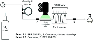
The intended chemistry under homogeneous conditions requires sufficient oxygen concentration in the mixture. For this purpose, the solution containing substrate and catalyst is pumped through a pressurized gas–liquid reactor for oxygen gas feeding (at 13 bar gas pressure) using a Vapourtec R Series pump module (Fig. 1). The commercially available reactor, also from Vapourtec, is configured as a reverse tube-in-tube system.27 Such design is particularly effective as liquid phase, flowing through the outer tube, is readily heated to desired temperature. The semi-permeable membrane, a fluoropolymer that prevents direct contact between the two phases, adapts to the liquid temperature and thus modulates permeability. The presence of surrounding liquid phase allows the inner tube to be pressurized with gaseous reagent without membrane rupture. A post cooling coil drives off heat from the gas-saturated liquid at reactor exit giving a mixture at ambient temperature. Liquid flow continues to the custom-designed photoreactor (fluorinated ethylene propylene, FEP, tubing mounted on a grid) which is irradiated by a white LED lamp (20 Watt, unless stated otherwise). A back pressure regulator (BPR, 250 psi ≅ 17.2 bar) at photoreactor exit allows for pressurization of the entire system (setup 2 in Fig. 1). A more detailed description of the setup is found in the ESI.†It should be kept in mind at all time that handling flammable solvents in combination with large amounts of oxidizer (oxygen) is dangerous. Above critical concentrations, an ignition source such as a spark from static discharge may cause explosion.28,29 The advantage of the closed, pressurized system is the lack of formation of highly flammable solvent vapours thus reducing risks. Moreover, at respective liquid and gas volumes of 15 mL and 4 mL in the gas–liquid reactor, risk assessment was favourable and safety of the system was rated acceptable.
Oxygen feed
Since concentration of dissolved oxygen is key for the planned homogeneous photooxygenations, efficiency of gas mass transfer to the liquid phase was investigated first. Oxygen saturation levels after passage through the gas–liquid reactor for methanol, acetonitrile, and dichloromethane (MeOH, MeCN, and DCM, respectively), all of which are common solvents for singlet oxygen oxidations, were evaluated according to following approach. Dissolving methylene blue (MB, 0.6 mM) in each of the solvents, liquid phase segments were readily distinguished from oxygen gas bubbles that appeared after depressurizing, i.e. downstream of the BPR (Fig. 2). For this purpose, the presence of the photochemical reactor was not essential and the BPR was installed directly after the gas–liquid reactor (setup 1, Fig. 1). Bubble size and frequency were then measured in a calibrated monitoring tube, allowing calculation of oxygen uptake in the gas–liquid reactor passage (for more details, see the ESI†).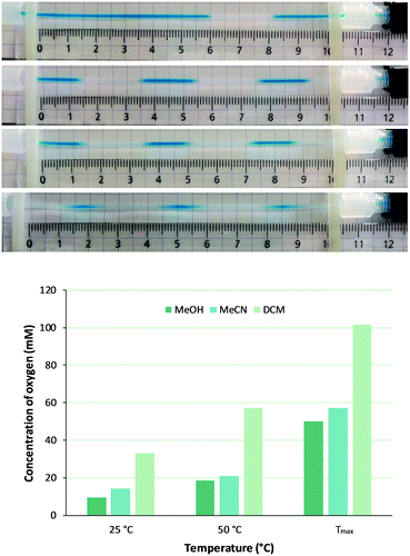 | ||
| Fig. 2 Upper panel: Effect of gas–liquid reactor membrane temperature on O2 supply as imaged by the segmented flow patterns emerging downstream of the 250 psi BPR for solutions of MB in (from top to bottom) MeOH at 25 °C, MeOH at 110 °C, MeCN at 110 °C, and DCM at 90 °C. Lower panel: Calculated concentration of O2 in MeOH, MeCN, and DCM at a constant flow rate of 1.0 mL min−1 but with increasing temperatures (Tmax is 110 °C for MeOH and MeCN, 90 °C for DCM). For more details, see the ESI.† | ||
Thus, with physical models of surface tension and fluid density,30 and mass transfer27,31 been reported elsewhere, intention here was to empirically quantify effect of membrane temperature and liquid flow rate on total oxygen feed. At constant liquid flow rate (1.0 mL min−1) bubble frequency increased with higher membrane temperature and, with bubble size being unaffected, obviously more gas was introduced (Fig. 2). For example, a fivefold increase of oxygen concentration in MeOH was achieved (from 9.5 mM to 50.0 mM) by membrane temperature raise from 25 °C to 110 °C. The high oxygen pressure and the presence of the BPR indeed allow to work well above normal boiling temperature. Similar observations as for MeOH were made for MeCN and DCM, the latter being particularly suitable for dissolving oxygen (Fig. 2). It is worth noting that this gas–liquid reactor membrane thus behaves different from other systems such as AF2400, in which permeability of the membrane (albeit for other gases than oxygen) drops with higher temperature.32,33
Shorter residence time in the gas–liquid reactor‡ (i.e., higher liquid flow rate) limits oxygen uptake as demonstrated for a MeOH solution at 50 °C (Fig. 3). This observation corroborates previous reports on the inverse relation between feed time and final gas concentration in tube-in-tube reactors.27 In this respect, it was noticed that comparable oxygen concentrations were reached at a flow rate of 0.25 mL min−1 at 50 °C (57 mM) as when operating at 1.0 mL min−1 and 110 °C (50 mM). The former setting may for example be favorable for use with low-boiling solvents or for synthesis of thermolabile products.
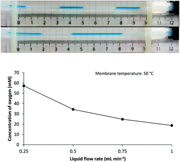 | ||
| Fig. 3 Upper panel: Effect of liquid phase flow rate on O2 supply as imaged by the segmented flow pattern emerging downstream of the 250 psi BPR for solutions of MB in MeOH at 50 °C membrane temperature and at a flow rate of (from top to bottom) 0.25 mL min−1 and 1.0 mL min−1. Lower panel: Calculated concentration of O2 in MeOH solutions at 50 °C membrane temperature being pumped at varying flow rates (for more details, see the ESI†). | ||
Application in photooxidation reactions
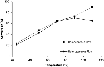
Having understood parameters that determine oxygen supply, proof of concept for 1O2-mediated photooxidations was pursued. A series of substrates was judiciously selected for validation, including the commercially available ethyl 3-(2-furyl)propanoate (1) (Scheme 1). Photooxidation affords the hydroperoxy derivative (2), the latter which serves as important intermediate for constructing complex polycycles in the total synthesis of various natural products.34 Initial experiments involved a 50 mM solution of 1 in MeOH as solvent, but also as source for the methoxy group, containing MB (0.1 mM) as photosensitizer. With the 2.5 mL photoreactor tube connected downstream of the gas–liquid reactor (i.e., setup 2) a flow rate of 1.0 mL min−1 corresponded to 2.5 minutes of white light irradiation. Under these conditions, conversion significantly increased when higher membrane temperatures were applied (Fig. 4), in line with the higher oxygen concentrations measured in earlier experiments (see Fig. 2). Highest conversion (90%) of 1 with practically total consumption of oxygen (i.e., no bubble formation was detected post-BPR) was reached at 110 °C. It should be emphasized here that higher temperature in the gas–liquid reactor does not affect kinetics of the photooxidation under investigation. The post cooling device (as mentioned before) reduces flow temperature to ambient level before entering the photoreactor. Efficiency of this cooling coil was confirmed by the comparable conversion obtained in a setup with active temperature reduction prior to photoreaction (details can be found in the ESI†). | ||
| Scheme 1 Photooxygenation of ethyl 3-(2-furyl)propanoate (1) in methanol gives the methoxylated hydroperoxy derivative (2). | ||
The conversion of 1 was repeated but with the photoreactor now installed downstream of the BPR (setup 1). Depressurization resulted in release of oxygen gas from the supersaturated solution and subsequent irradiation thus occurred under biphasic gas–liquid flow regime. Although the amount of oxygen in the system was the same as under homogeneous conditions, maximum conversion dropped to 65% (Fig. 4). The presence of residual gas segments at the photoreactor exit suggests sufficient oxygen was delivered but mass transfer from gas to liquid phase must have been rate limiting. Such situation rarely occurs in typical biphasic flow regimes because these are driven by high excess of oxygen. Resulting phenomena like thin liquid films lining the gas bubbles generate large interfacial contact which strongly facilitates mass transfer.11,15,17
Flow rate too determined conversion, as was expected from results presented in Fig. 3. Using setup 2 with membrane temperature set at 50 °C, complete conversion of 1 was reached at the lowest flow rate whereas only about half of the substrate was converted at highest rate (0.25 mL min−1 and 1.0 mL min−1, respectively) (Table 1). A faster passage through the gas–liquid reactor results in lower oxygen uptake (Fig. 3), but obviously also correlates to a shorter irradiation time. Although both can be the cause of lower conversion, the shorter residence time in the gas–liquid reactor was found decisive. Full consumption of oxygen indeed was observed for all flow rates as concluded from the lack of bubbles developing passed the BPR. Moreover, extending irradiation time without modifying flow rate by prolongation of the original 2.5 mL irradiation path to 6 mL (resulting in 6 min of irradiation instead of 2.5 min) did not affect conversion (Table 1, entries 4 and 5). The possibility of insufficient irradiation was thus refuted and lower conversions were attributed to decreased oxygen supply.
Productivity and scalability
In order to increase output, higher concentrations of 1 were reacted using a flow rate of 0.25 mL min−1 at 50 °C membrane temperature or 1.0 mL min−1 at 110 °C. Photooxygenation of 0.1 M of 1 afforded comparable conversions for both conditions, as demonstrated in Fig. 5. In the 0.2 M solution, a flow rate of 1.0 mL min−1 at 110 °C led to ∼50% lower conversion as compared to the slower flow at 50 °C as, presumably, shorter light exposure becomes more dominating too. Using these data, productivity and space time yield (STY) of the photochemical unit were determined (Table 2). Productivity is the overall output per unit of time and is calculated by multiplying substrate concentration by flow rate and by conversion. Space time yield is useful to compare performance in different reactor types,19 as reactor volume is accounted for too:| STY = n/(VPRt) |
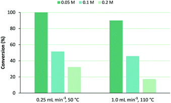 | ||
| Fig. 5 Influence of concentration of ethyl 3-(2-furyl)propanoate (1) on its conversion under selected flow rate and corresponding membrane temperature, using MeOH as solvent. | ||
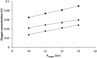
However, comparison of STY and benchmarking with other systems is trivial as key factors including irradiation source and amount (or excess) of oxidant are not considered. Since the gas–liquid reactor is purposed for safe administration of gaseous reagents, the gas feed chamber is deliberately small (4 mL in this case). Under most demanding conditions, i.e. at 1.0 mL min−1 flow rate and a membrane temperature of 110 °C, only 1.2 mL min−1 of oxygen gas is taken up in methanol (see ESI† for details). Such is significantly lower than with other reactors for which gas flows between 10 mL min−1 up to over 1 L min−1 are reported.11,19,21 Still, according to Henry's law higher saturation levels (thus higher productivity) could be reached by increasing oxygen pressure as demonstrated by the proportional relationship in Fig. 6. Unfortunately, gas supply to our system was limited by the standard two-stage gas pressure regulator with a maximum output of around 13 bar. However, up to 30 bar is tolerated according to membrane specifications, a pressure that is easily resisted by narrow bore FEP tubing of 0.4 mm wall thickness as used in the setup. Based on regression analysis (using data from Fig. 6) and extrapolation of solubility to higher pressures, oxygen concentration may thus be more than doubled (Table 3). Under these conditions photooxidation rate is expected to be much higher with significant increase in productivity as result. Moreover, the serial connection of two (or more) gas–liquid reactors is the proposed strategy35,36 for supplying even more oxygen according to the manufacturer's guidelines. On the other hand, a further increase in membrane temperature seems less relevant. Operating already close to the specified maximum of 150 °C, also solvent boiling (even under pressurized conditions) should be taken into account.
| Solvent | Slope | Intercept | R 2 | [Oxygen gas]b | ||
|---|---|---|---|---|---|---|
| P oxygen (bar) | ||||||
| 15 | 20 | 30 | ||||
| a Data taken from experiment described in Fig. 6. b Predicted dissolved oxygen gas concentration (M) in the different solvents at extrapolated gas pressures (Poxygen) of 15, 20, and 30 bar for a liquid flow rate of 1 mL min−1 and a membrane temperature of 110 °C for MeOH and MeCN, and 90 °C for DCM. | ||||||
| MeOH | 7.03 × 10⁻³ | −0.0424 | 0.994 | 0.06 | 0.10 | 0.17 |
| MeCN | 5.82 × 10⁻³ | −0.0152 | 0.994 | 0.07 | 0.10 | 0.16 |
| DCM | 8.23 × 10⁻³ | −0.0170 | 0.999 | 0.11 | 0.15 | 0.23 |
Scope and versatility
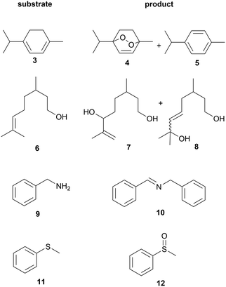
The concept of homogeneous photooxygenations in flow was put to the test using a series of suitable substrates with products known in the literature (Fig. 7). Further optimization of flow rate and membrane temperature to reach full conversion of ethyl 3-(2-furyl)propanoate (1), the model compound of this study, gave rise to formation of the desired hydroperoxy derivative (2) in excellent yield (entry 1a, Table 4). Using white light as irradiation source, replacing methylene blue with rose Bengal (RB) as photosensitizer did not affect conversion. Oxidation of α-terpinene (3) gave the anthelmintic endoperoxide ascaridole37,38 (4) in a yield of 90%, containing p-cymene (5) as a minor byproduct (entry 2a). Conversion dropped (to 64%) when higher flow rate and membrane temperature were applied (1.0 mL min−1 and 110 °C, respectively). In this case, insufficient irradiation time, rather than lack of oxygen, was decisive as full conversion with total consumption of oxygen was reached simply by upgrading to a 50 W LED source. The ascaridole productivity thus obtained, amounting to ∼2.6 mmoles h−1 (after taking into account the presence of the p-cymene impurity) is considerably higher than in a microcapillary film reactor (MCFR) driven by a similar gas feeding principle (0.14 mmoles h−1).23 On the other hand, the latter setup shows higher selectivity as p-cymene is not detected. As mentioned, however, several critical parameters are not accounted for in the productivity equation which makes quantitative comparison between systems extremely difficult. Most likely higher working pressure of the gas–liquid setup (∼13 bar with potential to raise to 30 bar) is decisive as indeed oxygen mass transfer is favoured when compared to the MCFR (4.5 bar applied). Accordingly, higher flow rates are feasible (typically 1 mL min−1vs. a reported maximum of 0.2 mL min−1 for the MCFR) which eventually lead to increased photoproduct output.| Substrate | Product | Entry | Sensitizer,a solvent | Flow rateb (mL min−1) | T (°C) | V PR (mL) | LEDe (W) | Conversionf (%) | Yieldg (%) | |
|---|---|---|---|---|---|---|---|---|---|---|
| Homog. | Heterog. | |||||||||
a Photosensitizers methylene blue (MB), rose bengal (RB), and tetraphenylporphyrin (TPP) used in concentration of 0.1 mM for all entries apart from entry 3a (0.2 mM).
b Flow rate of the liquid mixture.
c Membrane temperature in the gas–liquid reactor; photoreactions occur at room temperature.
d Photoreactor volume.
e Power of the white LED irradiation source.
f Conversions for reactions under homogeneous or heterogeneous conditions determined by GC-FID using decane as internal standard for entries 1a, 2a–2c, 3b–3e, 4 and by GC-MS/TLC for entries 1b and 3a.
g Isolated yield for homogeneous reactions described in entries 1a, 2a, 3b and 4a, yield for homogeneous reaction described in entry 5b was determined by GC based on calibration curve constructed from the reference material of 12 (see ESI for details).
h Diols 7 and 8 were obtained as an inseparable mixture of 1![[thin space (1/6-em)]](https://www.rsc.org/images/entities/char_2009.gif) : :![[thin space (1/6-em)]](https://www.rsc.org/images/entities/char_2009.gif) 1 regioisomers (ratio determined by NMR) after reduction of the hydroperoxides with NaBH4. 1 regioisomers (ratio determined by NMR) after reduction of the hydroperoxides with NaBH4.
|
||||||||||
| 1 | 2 | 1a | MB, MeOH | 0.5 | 70 | 2.5 | 20 | 100 | 100 | 90 |
| 1b | RB, MeOH | 0.5 | 70 | 2.5 | 20 | 100 | — | — | ||
| 3 | 4, 5 | 2a | RB, MeCN | 0.5 | 90 | 2.5 | 20 | 97 | 95 | 90 |
| 2b | RB, MeCN | 1.0 | 110 | 2.5 | 20 | 64 | — | — | ||
| 2c | RB, MeCN | 1.0 | 110 | 2.5 | 50 | 98 | — | — | ||
| 6 | 7, 8 | 3a | MB, DCM | 0.25 | 50 | 2.5 | 20 | 100 | — | — |
| 3bh | MB, MeCN | 0.5 | 90 | 2.5 | 20 | 99 | 89 | 94 | ||
| 3c | MB, MeCN | 1.0 | 90 | 2.5 | 20 | 79 | — | — | ||
| 3d | MB, MeCN | 1.0 | 90 | 2.5 | 50 | 87 | — | — | ||
| 3f | MB, MeCN | 1.0 | 90 | 6.0 | 20 | 85 | — | — | ||
| 9 | 10 | 4a | MB, MeCN | 0.25 | 100 | 2.5 | 20 | 100 | 33 | 57 |
| 4b | TPP, EtOAc | 0.5 | 90 | 2.5 | 20 | 100 | — | — | ||
| 11 | 12 | 5a | MB, DCM | 0.5 | 70 | 2.5 | 20 | 0 | — | — |
| 5b | MB, DCM | 0.5 | 70 | 6.0 | 50 | 0 | — | — | ||
| 5c | MB, MeOH | 0.5 | 70 | 6.0 | 50 | 86 | — | 85 | ||
Initial photooxidation experiments with citronellol (6) were performed in MeOH and using RB, the solvent and photosensitizer as used for industrial production of the fragrance rose oxide.39–42 Starting material was still detected after photoreaction at a flow rate of 0.25 mL min−1 and temperature of 70 °C (not shown). At the same flow rate but at lower membrane temperature, reaction was complete when using DCM as solvent and MB (0.2 mM) as photosensitizer (entry 3a). When solvent was changed to MeCN, containing MB (0.1 mM) almost full conversion and 94% yield were achieved, at a flow rate of 0.5 mL min−1, at 90 °C. Under these conditions, residual oxygen was observed at reactor exit, suggesting higher productivity was feasible. Doubling the flow rate led to a drop in conversion, which was compensated partly by installing the 50 W irradiation source (entries 3c and 3d, respectively). The same was achieved using the 20 W lamp but with the 6 mL photoreactor. In case of oxidative coupling of benzyl amine (9) in MeCN,43 complete conversion was obtained with moderate yield though (entry 4a). Most likely, the isolation step via chromatography impaired the fragile product (10). Ethyl acetate (EtOAc), although not investigated in detail in this work, was shown to be a good and more sustainable alternative to MeCN for this reaction. Using tetraphenylporphyrin (TPP) as sensitizer,44 full conversion with shorter residence time was observed (entry 4b). In a final set of experiments, the system was evaluated for oxidation of sulfides. Thioanisole (11), for example, was expected to be converted into the corresponding sulfoxide (12) but, remarkably, no reaction was observed in DCM. Changing to MeOH readily gave clean conversion to 12 (86%) practically without sulfone (<1%) formation (entry 5c).45
For comparison, selected reactions were also conducted under heterogeneous conditions by installing the photoreactor downstream of the BPR (setup 1 in Fig. 1). Lower conversions were observed in most cases, particularly in the oxidation of 9, confirming the advantages of homogeneous photooxidations (under near stoichiometric conditions).
Conclusions
A flow system for efficient light-induced oxygenations which is readily scalable is presented. The key feature of the system is the use of a gas–liquid reactor that enables mass transport of oxygen in an accurate and safe manner simply by adjusting liquid flow rate, membrane temperature, and gas pressure. Consistent and reproducible conditions give superior process control over biphasic flow regimes, which are often perturbed by excessive gas supply. Most promising, however, is the accurate oxygen supply which can be simply tuned to obtain full gas consumption. As such, photooxidation reactions can run in line with continuous downstream processing (e.g., reduction of hydroperoxides) which is not feasible in a biphasic flow regime running on oxygen excess. Real continuous manufacturing involving singlet oxygen photooxygenation steps thus becomes feasible, which is subject of our current research.Acknowledgements
This project was funded by the European Union's Seventh Framework Programme (FP7/2007-2013) Marie-Curie ITN Grant, Agreement No. 316975: SO2S, the singlet oxygen strategy. Vapourtec is gratefully acknowledged for providing the gas–liquid reactor. We thank Professor Annemieke Madder and Mr. Jos Van den Begin from Ghent University and Mr. Myron Triantafyllakis from University of Crete for their assistance with NMR.Notes and references
- M. C. DeRosa and R. J. Crutsley, Coord. Chem. Rev., 2002, 233–234, 351 CrossRef CAS
.
- B. M. Trost, Science, 1991, 254, 1471 CAS
.
- E. L. Clennan and A. Pace, Tetrahedron, 2005, 61, 6665 CrossRef CAS
.
- T. Montagnon, D. Kalaitzakis, M. Triantafyllakis, M. Stratakis and G. Vassilikogiannakis, Chem. Commun., 2014, 50, 15480 RSC
.
- A. A. Ghogare and A. Greer, Chem. Rev., 2016, 116, 9994 CrossRef CAS PubMed
.
- G. Ohloff, Pure Appl. Chem., 1975, 43, 481 CrossRef CAS
.
- D. Cambié, F. Zhao, V. Hessel, M. G. Debije and T. Noël, Angew. Chem., Int. Ed., 2017, 56, 1050 CrossRef PubMed
.
- R. C. R. Wootton, R. Fortt and A. J. de Mello, Org. Process Res. Dev., 2002, 6, 187 CrossRef CAS
.
- F. Wilkinson, W. P. Helman and A. B. Ross, J. Phys. Chem. Ref. Data, 1995, 24, 663 CrossRef CAS
.
- For reviews on continuous flow photochemistry, see: D. Cambié, C. Bottecchia, N. J. Straathof, V. Hessel and T. Noël, Chem. Rev., 2016, 116, 10276 CrossRef CAS PubMed
; H. P. L. Gemoets, Y. Su, M. Shang, V. Hessel, R. Luque and T. Noël, Chem. Soc. Rev., 2016, 45, 83 RSC
; V. Y. Su, N. J. W. Straathof, V. Hessel and T. Noël, Chem. – Eur. J., 2014, 20, 10562 CrossRef PubMed
; J. P. Knowles, L. D. Elliott and K. I. Booker-Milburn, Beilstein J. Org. Chem., 2012, 8, 2025 CrossRef PubMed
.
- F. Lévesque and P. H. Seeberger, Org. Lett., 2011, 13, 5008 CrossRef PubMed
.
- F. Lévesque and P. H. Seeberger, Angew. Chem., Int. Ed., 2012, 51, 1706 CrossRef PubMed
.
- O. Shvydkiv, C. Limburg, K. Nolan and M. Oelgemöller, J. Flow Chem., 2012, 2, 52 CrossRef CAS
.
- D. Ziegenbalg, G. Kreisel, D. Weiß and D. Kralisch, Photochem. Photobiol. Sci., 2014, 13, 1005 CAS
.
- T. S. A. Heugebaert, C. V. Stevens and C. O. Kappe, ChemSusChem, 2015, 8, 1648 CrossRef CAS PubMed
.
- A. Talla, B. Driessen, N. J. Straathof, L.-G. Milroy, L. Brunsveld, V. Hessel and T. Noël, Adv. Synth. Catal., 2015, 357, 2180 CrossRef CAS
.
- J. Schachtner, P. Bayer and A. J. von Wangelin, Beilstein J. Org. Chem., 2016, 12, 1798 CrossRef CAS PubMed
.
- T. Carofiglio, P. Donnola, M. Maggini, M. Rossetto and E. Rossi, Adv. Synth. Catal., 2008, 350, 2815 CrossRef CAS
.
- T. H. Rehm, S. Gros, P. Löb and A. Renken, React. Chem. Eng., 2016, 1, 636 CAS
.
- K. Jähnisch and U. Dingerdissen, Chem. Eng. Technol., 2005, 28, 426 CrossRef
.
- G. I. Ioannou, T. Montagnon, D. Kalaitzakis, S. A. Pergantis and G. Vassilikogiannakis, ChemPhotoChem., 2017, 1, 173 CrossRef
.
- Z. Amara, J. F. B. Bellamy, R. Horvath, S. J. Miller, A. Beeby, A. Burgard, K. Rossen, M. Poliakoff and M. W. George, Nat. Chem., 2015, 7, 489 CrossRef CAS PubMed
.
- K. S. Elvira, R. C. R. Wootton, N. M. Reis, M. R. Mackley and A. J. DeMello, ACS Sustainable Chem. Eng., 2013, 1, 209 CrossRef CAS
.
- C. P. Park, R. A. Maurya, J. H. Lee and D.-P. Kim, Lab Chip, 2011, 11, 1941 RSC
.
- K. Huvaere, Green Process. Synth., 2012, 1, 533 CAS
.
- For reviews on gas-liquid reactors, see: M. A. Mercadante and N. E. Leadbeater, Green Process. Synth., 2012, 1, 499 Search PubMed
; M. Brzozowski, M. O'Brien, S. V. Ley and A. Polyzos, Acc. Chem. Res., 2015, 48, 349 CrossRef CAS PubMed
; C. J. Mallia and I. R. Baxendale, Org. Process Res. Dev., 2016, 20, 327 CrossRef
.
- L. Yang and K. F. Jensen, Org. Process Res. Dev., 2013, 17, 927 CrossRef CAS
.
- A. Gavriilidis, A. Constantinou, K. Hellgardt, K. K. Hii, G. J. Hutchings, G. L. Brett, S. Kuhn and S. P. Marsden, React. Chem. Eng., 2016, 1, 595 CAS
.
- C. A. Hone, D. M. Roberge and C. O. Kappe, ChemSusChem, 2017, 10, 32 CrossRef CAS PubMed
.
- L. Chen, Y. S. Tian and T. G. Karayiannis, Int. J. Heat Mass Transfer, 2006, 49, 4220 CrossRef
.
- Y. Su, V. Hessel and T. Noël, AIChE J., 2015, 61, 2215 CrossRef CAS
.
- I. Pinnau and L. G. Toy, J. Membr. Sci., 1996, 109, 125 CrossRef CAS
.
- P. B. Cranwell, M. O'Brien, D. L. Browne, P. Koos, A. Polyzos, M. Peña-López and S. V. Ley, Org. Biomol. Chem., 2012, 10, 5774 CAS
.
- D. Kalaitzakis, A. Kouridaki, D. Noutsias, T. Montagnon and G. Vassilikogiannakis, Angew. Chem., Int. Ed., 2015, 54, 6283 CrossRef CAS PubMed
.
- Y. Su, K. Kuijpers, V. Hessel and T. Noël, React. Chem. Eng., 2016, 1, 73 CAS
.
- K. P. L. Kuijpers, M. A. H. van Dijk, Q. G. Rumeur, V. Hessel, Y. Su and T. Noël, React. Chem. Eng., 2017, 2, 109 CAS
.
- G. O. Schenck, Angew. Chem., 1952, 64, 12 CrossRef CAS
.
- H. Paget, J. Chem. Soc., 1938, 829 RSC
.
- W. Rojahn and H. U. Warnecke, Dragoco Rep., 1980, 27, 159 CAS
.
-
G. O. Schenck, G. Ohloff and E. Klein, US Pat., 3382276, 1968 Search PubMed
.
- N. Monnerie and J. Ortner, J. Sol. Energy Eng., 2001, 123, 171 CrossRef CAS
.
- D. Ravelli, S. Protti, P. Neri, M. Fagnoni and A. Albini, Green Chem., 2011, 13, 1876 RSC
.
- J. H. Park, K. C. Ko, E. Kim, N. Park, J. H. Ko, D. H. Ryu, T. K. Ahn, J. Y. Lee and S. U. Son, Org. Lett., 2012, 14, 5502 CrossRef CAS PubMed
.
- G. Jiang, J. Chen, J.-S. Huang and C.-M. Che, Org. Lett., 2009, 11, 4568 CrossRef CAS PubMed
.
- E. Bacciochi, C. Chiappe, C. Fasciani, O. Lanzalunga and A. Lapi, Org. Lett., 2010, 12, 5116 CrossRef PubMed
.
Footnotes |
| † Electronic supplementary information (ESI) available: Details of reactor setup, validation of the system with respect to oxygen feed, irradiation details, and general experimental procedures. See DOI: 10.1039/c7re00053g |
| ‡ To avoid confusion the term “residence time” refers to the time a solution remains in the gas–liquid reactor whereas the term “irradiation time” refers to the time a reaction mixture is exposed to light in the photoreactor. |
| This journal is © The Royal Society of Chemistry 2017 |

