 Open Access Article
Catechol adsorption on graphene nanoplatelets: isotherm, flat to vertical phase transition and desorption kinetics†
Lifu
Chen
,
Xiuting
Li
,
Eden E. L.
Tanner
and
Richard G.
Compton
 *
*
Department of Chemistry, Physical and Theoretical Chemistry Laboratory, Oxford University, South Parks Road, Oxford OX1 3QZ, UK. E-mail: richard.compton@chem.ox.ac.uk; Fax: +44 (0)1865 275410; Tel: +44 (0)1865 275957
First published on 4th May 2017
Abstract
The adsorption of catechol (1,2-dihydroxybenzene) on graphene nanoplatelets (GNPs) is investigated electrochemically and spectroscopically. The reversible adsorption of catechol on GNPs is Langmuirian with an adsorption constant of (0.2 ± 0.002) mM−1 at low adsorbate concentrations (≤100 mM). At higher concentrations (>100 mM) the adsorption of catechol on GNPs is shown to undergo a flat to vertical concentration driven phase transition. The kinetics of desorption are measured with a single particle electrochemical technique. The study of individual impacts allows the determination of the rate of catechol desorption from GNPs to be k = 0.08 ± 0.01 s−1 with first order kinetics. The method provides a powerful and efficient generic approach to study adsorption and, importantly, desorption of molecules on nanomaterials, as well as giving insight into the modification process.
Introduction
Graphene, due to its large thermal and electronic conductivities, high electron and carrier mobility, great surface area and strong intrinsic mechanical strength, has been actively investigated over recent decades.1–6 A broad range of potential applications have been extensively reported,6–25 of which two particularly interesting branches are the development of highly sensitive graphene-based chemical14 and biological22,23 sensors, and the use of graphene as a catalyst.24,25 To underpin such studies, it is of fundamental interest to quantify and gain further understanding of the adsorption of diverse molecules on graphene.Hitherto, the adsorption of various types of small molecules or atoms on graphene have been studied, notably metal atoms (Li,26 Zn,27etc.), gas molecules (CO2,28 N2,29 H2,30 H2S,31etc.), halogens32–34 and organic molecules (methane,35 dibenzothiophene,36 methanol,37etc.) where much of the work was theoretically investigated using quantum mechanical calculations based on density functional theory (DFT).26,27,29–35,37 The experimental data were usually obtained using scanning electron microscopy (SEM), Raman spectroscopy and X-ray spectroscopy (XPS).38–40 In contrast little is known about the adsorption of larger, especially organic, molecules on graphene. In this paper, we focus on the adsorption of 1,2-dihydroxybenzene (‘catechol’) on graphene from aqueous solution making use of a relatively new electrochemical method – that of nano-impacts – here novelly applied to the measurement of adsorption and desorption phenomena as well as complementary spectroscopic data.
Graphene nanoplatelets (GNPs), belonging to the family of graphene materials, preserve many of the appealing properties but circumvent the poor stability of single-layer graphene,20,41 due to structural distortion of rippling at 1 nm width.42 Meanwhile, GNPs are more commercially available and easier to produce and handle,20,43 which makes them an attractive alternative.
The molecular orientation of aromatic compounds adsorbed at platinum electrodes, including an assortment of 40 quinones and phenols, have been extensively studied by Hubbard's group.44–50 There are two orientation states, namely horizontal orientation with aromatic ring parallel to the adsorbent surface and vertical orientation with a perpendicular aromatic ring. For instance, adsorption of hydroquinone at low concentrations of adsorbate adopts a horizontal orientation but reorients to the vertical form when exposed to a solution containing higher concentrations.50
Herein, the adsorption and desorption of catechol molecules on GNPs were studied via nano-impacts51 which detects stochastic collisions of individual nanoparticles with a carbon wire electrode by virtue of their Brownian motion in solution. By potentiostatting the electrode at a suitable potential, mediated electron transfer occurs on the surface of the impacting nanoparticle during collision,51–55 giving rise to a current spike in chronoamperometry. In this work, GNPs are modified by different concentrations of catechol and studied with the nano-impact method. In the latter, suspended particles collide randomly with an electrode. The surface coverage of the electroactive catechol on faradaically non-active GNPs can be obtained, based on the charge passed per spike leading to the number of adsorbed catechol molecules at the single-GNP entity level. Therefore, it can be used to probe the kinetics of desorption of catechol from GNPs as the surface progressively depletes when in contact with a solution which does not contain catechol. UV-Vis studies are conducted to investigate the catechol adsorption isotherm for GNPs and determine the orientation state of catechol molecules on the GNPs: at low coverage, a reversible Langmuirian adsorption is seen but with a flat to vertical phase transition driven at high concentrations of catechol in solution. The approach is generic and could be applied to study the adsorption and desorption of various kinds of molecules on nanomaterials, such as GNPs, carbon nanotubes (CNTs) and nanodots, among others.
Experimental
Chemicals and reagents
Graphene nanoplatelets (GNPs, 15 μm in width, 6–8 nm in thickness) with an average area of 297 ± 152 μm2 (estimated from scanning electron microscopy56) were purchased from Strem Chemicals, MA, USA. The surface oxygen species on the GNPs (ether, carboxyl or hydroxyl functional groups) amount to a total oxygen content of less than 1% and a residual acid content of less than 0.5% by weight.56–58 All other chemicals were provided from Sigma-Aldrich at reagent grade unless specified otherwise, and used as received without further purification.All solutions were made up with deionised water of resistivity not less than 18.2 MΩ cm (Millipore) at 298 K. pH 3.0 buffer solution was freshly prepared from 0.1 M citric acid/sodium citrate with 0.1 M KCl supporting electrolyte. It has been reported that catechol is stable in a pH 3.0 environment,59 and thus all following experiments were conducted in pH 3.0. pH buffers were measured by using a Hannah pH 231 pH meter (Hannah, Bedfordshire, UK), and degassed thoroughly with pure nitrogen (BOC Gases plc, UK) for 20 min to prevent degradation of the solution by atmospheric oxygen prior to the addition of catechol.
Preparation of GNP suspensions
A suspension of 3.3 × 10⁻¹³ M of unmodified GNPs was prepared by mixing 2.8 mg of GNPs with 5 mL buffer solution. To generate an evenly dispersed suspension, the mixture was sonicated (FB15050, Fisher Scientific, 50/60 Hz, 80 W, Germany) for 15 min. The above suspension was used as a stock solution, and diluted for nano-impact experiments. Fresh suspensions were prepared daily.To prepare catechol modified GNPs, 2.8 mg of GNPs was added to 10 mL of catechol solution and then sonicated for 25 min. The mixture was then centrifuged (Eppendorf Centrifuge 5702) for 13 min in 3000 rpm. The settled solids were washed thoroughly with 10 mL of pH 3.0 buffer solution to remove excess catechol. Further centrifugation was conducted and the settled modified GNPs powder was added into 5 mL of pH 3.0 aqueous buffer solution. The mixture was shaken on a vortex (Whirlmixer, Loughbough, UK) for 30 s and sonicated for 20 s. This dispersion procedure was repeated 3 times to get an even suspension. The above stock suspension was freshly prepared every day.
Two different concentrations of catechol solutions were used to modify GNPs. The GNPs that were modified by 100 mM catechol solution are noted as 100-catechol GNPs while GNPs modified by 300 mM catechol solution are to be noted as 300-catechol GNPs in the following sections.
Carbon fibre micro electrode fabrication
The method of carbon fibre micro electrode fabrication follows that developed by Ellison et al.60 Briefly, a carbon fibre (diameter 7.0 μm, Goodfellow, Cambridge, UK) was connected to a metal wire using silver epoxy (RS Components Ltd.) conductive adhesive, which was then placed in an oven for 15 min at approximately 60 °C to set the adhesive. The wire was threaded through a plastic pipette tip. The interstice between wire and tip was sealed using cyanoacrylate adhesive and the wire slowly pulled down, leaving only the carbon fibre extended out of the end, and left overnight to ensure set the cyanoacrylate adhesive. Finally, the carbon fibre was cut to approximate 1 mm length.Electrochemical procedures
Electrochemical experiments were conducted at 25 °C inside a Faraday cage with a standard three-electrode system by using a μAutolab II potentiostat (Metrohm-Autolab BV, Netherlands) and NOVA 1.10 software.Cyclic voltammetry at EPPG electrodes
For the cyclic voltammetry measurements, an edge-plane pyrolytic graphite (EPPG, IJ Cambria Scientific Ltd, Llanelli, UK) electrode (radius 1.5 mm) was used as the working electrode, a saturated calomel electrode (SCE, ALS distributed by BASi, Tokyo, Japan) as the reference and a graphite rod as the counter electrode. Prior to each modification, the EPPG electrode was polished using alumina of decreasing particle size (1.0, 0.3 and 0.05 μm, Buehler, IL, UK), sonicated in water, and dried with nitrogen. 10 μg of modified/unmodified GNPs were drop-casted on the EPPG electrode and left under a N2 environment to dry fully. For comparison, the same experiment was conducted by drop-casting 5 μL of 2 mM catechol on the EPPG electrode. A cyclic voltammogram (CV) was then recorded at scan rate of 25 mV s−1 in a degassed pH 3.0 buffered solution.Nano-impact experiments
In nano-impact experiments, chronoamperometry was recorded at a carbon fibre wire electrode with the same reference electrode and counter electrode as above. Note the potentiostat used in this work accurately conserves the charge transferred due to a particle-impact process despite possible alteration in the spike shape.61,62 4.5 mL of pH 3.0 buffered solution was bubbled with nitrogen for 5 min to remove dissolved electroactive oxygen and then 500 μL of modified/unmodified GNPs stock suspension was added while the nitrogen was kept bubbling for further 10 s to get an even suspension, followed by immediate chronoamperometric scans. Chronoamperograms were recorded for 20 s at different potentials from +0.2 to +1.1 V. The program “SignalCounter” developed by Dr D. Omanović (Centre for Marine and Environmental Research Zagreb, Croatia) was used for impact spike identification and individual spike area determination.63UV experiments
UV/Vis studies were performed in 10 mm width quartz cells by a Shimadzu UV-1800 UV spectrophotometer. For all measurements, a baseline correction was conducted prior to analysis, and the absorbance was recorded from 500–200 nm.Results and discussion
This section first reports the adsorption of catechol onto GNPs, which is evidenced by the cyclic voltammetry of an ensemble of catechol–GNPs on a macro EPPG electrode. Second, complementary UV-Vis experiments are performed to further study the adsorption of catechol on GNPs. Finally, chronoamperometry of a micro wire electrode in catechol–GNPs suspension is conducted. The charge transfer at single catechol–GNPs with different applied potentials is investigated and individual current spikes analysed.Cyclic voltammetry of catechol modified GNPs
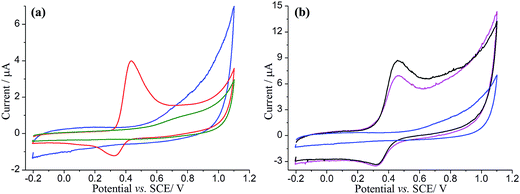
First, a CV of a catechol modified EPPG electrode was conducted to evidence the electroactivity of the catechol. The EPPG electrode was modified by drop-casting with 5 μL of 2 mM catechol, dried under a nitrogen atmosphere, and then immersed in degassed pH 3.0 buffer solution. Cyclic voltammetry was then recorded from −0.20 to +1.10 V vs. SCE and reversed back to −0.20 V at a scan rate of 25 mV s−1 (Fig. 1a, red line). For comparison, the cyclic voltammetry of an unmodified EPPG was also recorded under the same conditions (Fig. 1a, green line). In the presence of catechol, a single oxidation peak was observed at ca. +0.43 V vs. SCE, which is consistent with previous reports on the oxidation of catechol.59,64 Note that the oxidation of catechol (C) forms o-benzoquinone (Q) at these potentials and at the pH studied is understood to follow the mechanism below:| C − e− ⇆ S | (1) |
| 2S → Q + C | (2) |
Next, in order to investigate the adsorption of catechol on GNPs, an EPPG electrode was modified by drop-casting with 10 μg of 100-catechol GNPs and cyclic voltammograms were recorded between −0.20 and +1.10 V vs. SCE at a scan rate of 25 mV s−1 (Fig. 1b, magenta line). This experiment was repeated for 300-catechol GNPs (Fig. 1b, black line), which showed a higher oxidative peak suggesting greater adsorption of catechol on the GNPs. Well-defined oxidative and reductive peaks, for both concentrations of catechol modified GNPs, were observed at ca. +0.46 V and +0.32 V vs. SCE, respectively, which are close to the peak potentials of drop-cast catechol on the EPPG (Fig. 1a, red line). This is in good agreement with literature,59,65 confirming that the GNPs were successfully modified with catechol. A control experiment of unmodified-GNPs drop-cast onto an EPPG was also conducted in the same solution and no redox signal was detected (Fig. 1a, blue line). Note that the enlarged background current in the presence of unmodified GNPs is a result of increased capacitance.
UV-Vis studies of catechol adsorption on GNPs
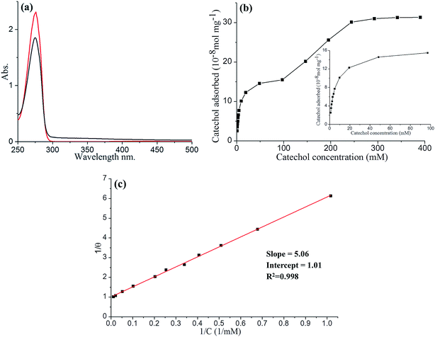
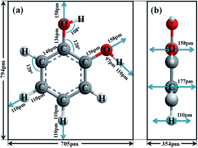
To further study the adsorption of catechol on GNPs, UV-Vis experiments were performed. 1 mL of various concentrations of catechol in pH 3.0 buffer was mixed with GNPs and then sonicated for 30 min to promote adsorption, followed by centrifugation. The original catechol solution and supernatant after adsorption were both examined using UV-Vis spectroscopy, allowing the amount of catechol adsorbed by GNPs to be determined. As shown in Fig. 2a, the absorbance peak is at 276 nm, consistent with literature reports.66,67 The reduction in the magnitude of the catechol absorbance peak is due to the adsorption of GNPs. The catechol adsorption isotherm for GNPs in pH 3.0 buffered solution was then plotted (Fig. 2b), where two clear plateaux can be observed. As the concentration of catechol increases, the amount of catechol adsorbed by 1 mg of GNPs (n) increases and reaches the first plateau at a catechol concentration of between ca. 50 and 100 mM with nmax = 1.6 × 10⁻⁷ mol mg−1, giving the maximum surface coverage (Γmax) of (2.5 ± 0.8) × 10−10 mol cm−2, and then reaches the second plateau at concentration around ca. 250 and 400 mM with n′max = 3.2 × 10⁻⁷ mol mg−1, giving Γ′max of (5.1 ± 1.7) × 10−10 mol cm−2. The area of the catechol molecule (Scatechol) can be estimated by approximating catechol as a rectangular box with all side lengths estimated by trigonometry for bond lengths, bond angles and van de Waals radii of terminating atoms68 (Scheme 1). Scatechol of flat view and S′catechol of edgewise view hence can be estimated as 5.6 × 10⁻¹⁵ cm2 and 2.8 × 10⁻¹⁵ cm2 respectively, which is in good agreement with literature.44,46,65Thus, the area occupied by each individual catechol molecule (SR-Ct) on GNP from UV-Vis results can be determined as SR-Ct = (6.7 ± 1.7) × 10−15 cm2 in 100 mM catechol and SR-Ct = (3.3 ± 0.8) × 10−15 cm2 in 300 mM catechol, consistent with the flat catechol molecule area of 5.6 × 10⁻¹⁵ cm2 (Scheme 1a) and edgewise catechol molecule area of 2.8 × 10⁻¹⁵ cm2 respectively. This gives the physical insight that at low concentrations (≤100 mM), catechol molecules adopt a flat orientation adsorbed on the GNP surface, whilst at high concentrations (≥150 mM) they adopt an edgewise orientation. At intermediate concentrations, it remains an open question if the different oriented molecules are locally organised or randomly distributed.
Last, as shown in Fig. 2c, the low concentration data (≤100 mM) were analysed in terms of the Langmuir model, which predicts the fractional coverage θ to vary with adsorbate concentration, C,
 | (3) |
Nano-impacts of catechol–GNPs and unmodified-GNPs
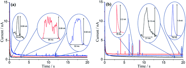
Having evidenced the adsorption of catechol on the GNPs electrochemically and spectroscopically, nano-impact experiments of catechol–GNPs were conducted to study individual catechol modified GNPs. From the cyclic voltammetry, oxidation of catechol may occur when the applied potential on the electrode is held at or more positive than ca. +0.43 V. A clean carbon fibre microelectrode was first immersed in solution and after the addition of a stock GNPs suspension with a known concentration (0.33 pM), chronoamperograms were immediately recorded at +0.5 and +0.9 V vs. SCE. For comparison, chronoamperograms were also recorded for unmodified GNPs in the same conditions. As shown in Fig. 3, oxidative spikes were observed for both catechol–modified GNPs and unmodified GNPs, with each spike corresponding to an individual collision between single GNP and the electrode. The average charge passed per spike (Q) at each potential was quantified by averaging the integration of each individual spike and a slow decrease in the size of the spikes from the modified GNPs was seen with time. This is discussed below and attributed to slow desorption of catechol.Two possible types of charge transfer process may be involved in a collision between a GNP and the microelectrode, namely faradaic and capacitative. The corresponding physical origins of these two processes have been elaborated in previous work.56,69,70 Briefly, a threshold potential is required to be applied in faradaic impacts to drive the redox reaction, leading a sharp increase in the charge transferred during the impact timescale. In contrast, when the applied potential deviates from the potential zero charge (PZC) of the electrode–electrolyte interface, a steady increase in charge transferred is shown for capacitative impacts. Upon elevation of the applied potential, the average charge (Q) for unmodified GNPs increases slightly (Fig. 3, black line), consistent with capacitative behaviour. In contrast, a large increase in Q for 100-catechol (Fig. 3, red line) and 300-catechol (Fig. 3, blue line) GNPs, respectively, is observed between +0.5 and +0.9 V. This implies that faradaic current from the oxidation of catechol on the individual impacting catechol–GNPs plays a dominant role in the observed current spikes while the simultaneous capacitative charge transfer caused by the GNPs is negligible. Fig. 3 also shows that the impact features are either in the form of ‘sharp spikes’ (short transient times) or ‘flat topped spikes’ (long transient times) and the spikes at low potential are of significantly longer duration with altered spike shapes.
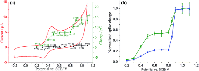
In order to better understand the difference in the charge per spike between the two different concentrations of catechol modified GNPs, a potential variation study was performed. 0.28 mg of catechol–modified or unmodified GNPs was well dispersed in 5 mL of nitrogen saturated pH 3.0 buffered solution. Chronoamperograms were then recorded at different potentials, from +0.2 to +1.1 V. The experiment at each potential was repeated to obtain a large sample size. The frequency of impacts are analysed in ESI, Fig. S2.† The average charge transferred per individual impact spike (Q) was plotted against the applied potential, as shown in Fig. 4.
The charge transferred per spike of unmodified GNPs (black square) shows a steady small increase with a higher applied potential, consistent with capacitative behaviour as previously reported.56,69 It is clear that there are two onsets of potential at ca. +0.43 V and +0.85 V, respectively, and both are quinone related. The two features are reminiscent of the oxidation of catechol adsorbed on alumina.65 Similarly it can be concluded that the first feature relates to incomplete catechol oxidation since the duration of the impact is too short to allow for full charge propagation over the surface and for the disproportionation kinetics of S to form C and Q to take place. The feature at the more positive potentials is likely related to catechol oxidation via a direct two electron process:
| C − 2e− ⇆ Q | (4) |
The difference in spike shapes suggest that at the low potential the oxidation is kinetically limited consistent with the flat topped spikes seen, whereas the faster, high potential process leads to sharper peaks and more complete oxidation of the adsorbed species. Experiments conducted with different levels of adsorbate (100-catechol GNP and 300-catechol GNP) showed the relative size of two features to vary: the higher coverage leading to a relatively larger signal consistent with the second order kinetics of the S disproportionation influencing the rate.
The surface coverage (Γ) of 300-catechol GNPs can be quantified based on Fig. 4. At +1.0 V, the average charge passed per spike due to the faradaic process (Qfaradaic) can be determined via Qtotal = Qfaradaic + Qcapacitative, where Qtotal = (13.6 ± 1.3) pC and Qcapacitative = (0.81 ± 0.05) pC. Qfaradaic can be related to the number of catechol molecules adsorbed per GNP (N) by Qfaradaic = nNe, where n is the number of electrons transferred during the oxidation of catechol (n = 2) and e is the charge per electron. The area occupied by each individual catechol molecule (SR-Ct) on the surface of GNP can be obtained via SR-Ct = SGNP/N, where SGNP is the area of GNP (equivalent to 297 ± 152 μm2).56 Moreover, Γ can be determined via Γ = N/(NASGNP), where NA is the Avogadro constant. Therefore, at +1.0 V, N, SR-Ct and Γ can be calculated as (4.0 ± 0.4) × 107, (7.4 ± 4.1) × 10−14 cm2 per molecule, and (2.2 ± 0.9) × 10−11 mol cm−2, respectively.
The theoretical number of catechol molecules for monolayer adsorption per GNP (N′) can be estimated from N′ = SGNP/Scatechol assuming a close packed coverage, hence N′ can be calculated as (5.3 ± 2.6) × 108. N obtained from nano-impacts at +1.0 V is (4.0 ± 0.4) × 107, which indicates a submonolayer coverage of catechol on the GNP. The reason for the submonolayer coverage and lower coverages relative to those inferred via UV-visible spectroscopy might be the progressive desorption of catechol molecules from GNPs before and during the nano-impact experiment following immersion into a solution containing no catechol, which is further confirmed by analysis of the spike charge with time, as next discussed.
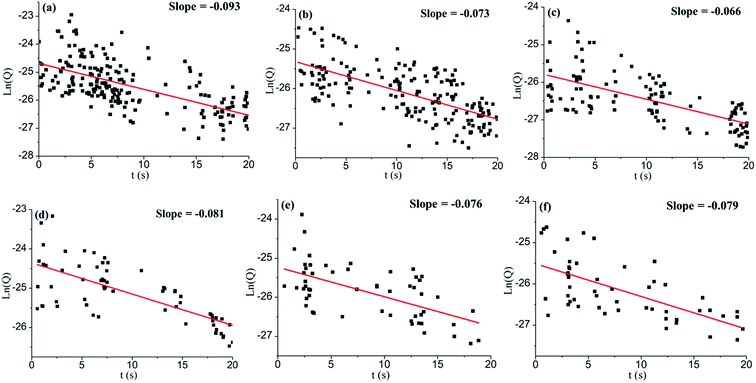
Six representative chronoamperometric scans with large spike sample size from both 100-catechol and 300-catechol GNPs, and different potentials were selected and single first order analysis of each spike was made. The average spike charge, Q, decreased with time. As the catechol adsorbed on a GNP is proportional to the charge, a clear steady decrease in the amount of catechol on GNP was inferred and attributed to the desorption process. Assuming first order desorption kinetics, plots of ln(Q) against time were made and are shown in Fig. 5 (additional scans are shown in Fig. S3†). Although the data is scattered, a reasonable linear dependence is seen. It can be concluded that the desorption of catechol on GNPs during chronoamperometric scans undergoes first order kinetics with a rate constant of k = 0.08 ± 0.01 s−1.
In summary, the adsorption of catechol on GNPs is reversible and at low concentration Langmuirian. At high concentrations, a flat to vertical phase transition change is inferred. In the absence of catechol in both solutions there is a slow first order desorption of the adsorbate.
Conclusions
The adsorption of catechol on GNPs follows the Langmuir model with the adsorption constant (K) of (0.2 ± 0.002) mM−1 at a low catechol concentration but with a flat to vertical phase transition occurring at high concentrations. The desorption process is a slow first order kinetics with a rate constant of k = 0.08 ± 0.01 s−1. A powerful new strategy is thus demonstrated to study adsorption and desorption of catechol on GNPs, and better understand the modification process, whose use can also be extended to the characterisation of various kinds of molecules on nanomaterials of industrial interest. This may significantly assist the potential environmental, biological and medical application of GNPs and other similar nanomaterials.Acknowledgements
The research leading to these results has received partial funding from the European Research Council under the European Union's Seventh Framework Programme (FP/2007–2013)/ERC Grant Agreement no. [320403]. X. L. thanks the China Scholarship Council for funding.References
- K. S. Novoselov, A. K. Geim, S. V. Morozov, D. Jiang, Y. Zhang, S. V. Dubonos, I. V. Grigorieva and A. A. Firsov, Science, 2004, 306, 666–669 CrossRef CAS PubMed.
- S. V. Morozov, K. S. Novoselov, M. I. Katsnelson, F. Schedin, D. C. Elias, J. A. Jaszczak and A. K. Geim, Phys. Rev. Lett., 2008, 100, 016602 CrossRef CAS PubMed.
- K. N. Kudin, B. Ozbas, H. C. Schniepp, R. K. Prud'homme, I. A. Aksay and R. Car, Nano Lett., 2008, 8, 36–41 CrossRef CAS PubMed.
- C.-H. Park, F. Giustino, C. D. Spataru, M. L. Cohen and S. G. Louie, Nano Lett., 2009, 9, 4234–4239 CrossRef CAS PubMed.
- A. Ambrosi, C. K. Chua, A. Bonanni and M. Pumera, Chem. Rev., 2014, 114, 7150–7188 CrossRef CAS PubMed.
- A. H. Castro Neto, F. Guinea, N. M. R. Peres, K. S. Novoselov and A. K. Geim, Rev. Mod. Phys., 2009, 81, 109–162 CrossRef CAS.
- A. K. Geim and K. S. Novoselov, Nat. Mater., 2007, 6, 183–191 CrossRef CAS PubMed.
- S. Stankovich, D. A. Dikin, G. H. B. Dommett, K. M. Kohlhaas, E. J. Zimney, E. A. Stach, R. D. Piner, S. T. Nguyen and R. S. Ruoff, Nature, 2006, 442, 282–286 CrossRef CAS PubMed.
- A. K. Geim, Science, 2009, 324, 1530–1534 CrossRef CAS PubMed.
- K. S. Kim, Y. Zhao, H. Jang, S. Y. Lee, J. M. Kim, K. S. Kim, J. H. Ahn, P. Kim, J. Y. Choi and B. H. Hong, Nature, 2009, 457, 706–710 CrossRef CAS PubMed.
- D. Li, M. B. Müller, S. Gilje, R. B. Kaner and G. G. Wallace, Nat. Nanotechnol., 2008, 3, 101–105 CrossRef CAS PubMed.
- A. A. Balandin, S. Ghosh, W. Bao, I. Calizo, D. Teweldebrhan, F. Miao and C. N. Lau, Nano Lett., 2008, 8, 902–907 CrossRef CAS PubMed.
- D. R. Dreyer, S. Park, C. W. Bielawski and R. S. Ruoff, Chem. Soc. Rev., 2010, 39, 228–240 RSC.
- F. Schedin, A. K. Geim, S. V. Morozov, E. W. Hill, P. Blake, M. I. Katsnelson and K. S. Novoselov, Nat. Mater., 2007, 6, 652–655 CrossRef CAS PubMed.
- S. Bae, H. Kim, Y. Lee, X. Xu, J. S. Park, Y. Zheng, J. Balakrishnan, T. Lei, H. Ri Kim, Y. I. Song, Y. J. Kim, K. S. Kim, B. Özyilmaz, J. H. Ahn, B. H. Hong and S. Iijima, Nat. Nanotechnol., 2010, 5, 574–578 CrossRef CAS PubMed.
- Y. Zhu, S. Murali, W. Cai, X. Li, J. W. Suk, J. R. Potts and R. S. Ruoff, Adv. Mater., 2010, 22, 3906–3924 CrossRef CAS PubMed.
- A. Reina, X. Jia, J. Ho, D. Nezich, H. Son, V. Bulovic, M. S. Dresselhaus and K. Jing, Nano Lett., 2009, 9, 30–35 CrossRef CAS PubMed.
- D. A. Dikin, S. Stankovich, E. J. Zimney, R. D. Piner, G. H. B. Dommett, G. Evmenenko, S. T. Nguyen and R. S. Ruoff, Nature, 2007, 448, 457–460 CrossRef CAS PubMed.
- Y. Hernandez, V. Nicolosi, M. Lotya, F. M. Blighe, Z. Sun, S. De, I. T. McGovern, B. Holland, M. Byrne, Y. K. Gun'ko, J. J. Boland, P. Niraj, G. Duesberg, S. Krishnamurthy, R. Goodhue, J. Hutchison, V. Scardaci, A. C. Ferrari and J. N. Coleman, Nat. Nanotechnol., 2008, 3, 563–568 CrossRef CAS PubMed.
- K. S. Novoselov, V. I. Fal'Ko, L. Colombo, P. R. Gellert, M. G. Schwab and K. Kim, Nature, 2012, 490, 192–200 CrossRef CAS PubMed.
- F. Schwierz, Nat. Nanotechnol., 2010, 5, 487–496 CrossRef CAS PubMed.
- A. Bonanni, C. K. Chua, G. Zhao, Z. Sofer and M. Pumera, ACS Nano, 2012, 6, 8546–8551 CrossRef CAS PubMed.
- A. H. Loo, A. Bonanni and M. Pumera, Nanoscale, 2013, 5, 7844–7848 RSC.
- Y. Liang, Y. Li, H. Wang, J. Zhou, J. Wang, T. Regier and H. Dai, Nat. Mater., 2011, 10, 780–786 CrossRef CAS PubMed.
- L. Qu, Y. Liu, J. B. Baek and L. Dai, ACS Nano, 2010, 4, 1321–1326 CrossRef CAS PubMed.
- D. Krepel and O. Hod, J. Phys. Chem. C, 2013, 117, 19477–19488 CAS.
- L. Hu, X. Hu, X. Wu, C. Du, Y. Dai and J. Deng, Phys. B, 2010, 405, 3337–3341 CrossRef CAS.
- A. K. Mishra and S. Ramaprabhu, AIP Adv., 2011, 1, 032152 CrossRef.
- B. Rani and K. Dharamvir, Int. J. Quantum Chem., 2014, 114, 1619–1629 CrossRef CAS.
- V. V. Ivanovskaya, A. Zobelli, D. Teillet-Billy, N. Rougeau, V. Sidis and P. R. Briddon, Eur. Phys. J. B, 2010, 76, 481–486 CrossRef CAS.
- S. Sharma and A. S. Verma, Phys. B, 2013, 427, 12–16 CrossRef CAS.
- H. Widjaja, Z. T. Jiang, M. Altarawneh, C. Y. Yin, B. M. Goh, N. Mondinos and B. Z. Dlugogorski, Appl. Surf. Sci., 2015, 356, 370–377 CrossRef CAS.
- H. Şahin and S. Ciraci, J. Phys. Chem. C, 2012, 116, 24075–24083 Search PubMed.
- H. Widjaja, Z. T. Jiang, M. Altarawneh, C. Y. Yin, B. M. Goh, N. Mondinos, A. Amri and B. Z. Dlugogorski, Appl. Surf. Sci., 2016, 373, 65–72 CrossRef CAS.
- C. Thierfelder, M. Witte, S. Blankenburg, E. Rauls and W. G. Schmidt, Surf. Sci., 2011, 605, 746–749 CrossRef CAS.
- H. S. Song, C. H. Ko, W. Ahn, B. J. Kim, E. Croiset, Z. Chen and S. C. Nam, Ind. Eng. Chem. Res., 2012, 51, 10259–10264 CrossRef CAS.
- E. Schröder, J. Nanomater., 2013, 2013, 6 Search PubMed.
- A. M. Pinto, J. A. Moreira, F. D. Magalhães and I. C. Gonçalves, Colloids Surf., B, 2016, 146, 818–824 CrossRef CAS PubMed.
- J. Wang, Z. Chen and B. Chen, Environ. Sci. Technol., 2014, 48, 4817–4825 CrossRef CAS PubMed.
- O. Mabayoje, M. Seredych and T. J. Bandosz, ACS Appl. Mater. Interfaces, 2012, 4, 3316–3324 CAS.
- L. Liu, S. Ryu, M. R. Tomasik, E. Stolyarova, N. Jung, M. S. Hybertsen, M. L. Steigerwald, L. E. Brus and G. W. Flynn, Nano Lett., 2008, 8, 1965–1970 CrossRef CAS PubMed.
- J. C. Meyer, A. K. Geim, M. I. Katsnelson, K. S. Novoselov, T. J. Booth and S. Roth, Nature, 2007, 446, 60–63 CrossRef CAS PubMed.
- J. Shen, Y. Hu, C. Li, C. Qin, M. Shi and M. Ye, Langmuir, 2009, 25, 6122–6128 CrossRef CAS PubMed.
- M. P. Soriaga and A. T. Hubbard, J. Am. Chem. Soc., 1982, 104, 2735–2742 CrossRef CAS.
- M. P. Soriaga and A. T. Hubbard, J. Am. Chem. Soc., 1982, 104, 2742–2747 CrossRef CAS.
- M. P. Soriaga and A. T. Hubbard, J. Am. Chem. Soc., 1982, 104, 3937–3945 CrossRef CAS.
- V. K. F. Chia, M. P. Soriaga and A. T. Hubbard, J. Phys. Chem., 1983, 87, 232–235 CrossRef CAS.
- D. Song, M. P. Soriaga, K. L. Vjeira, D. C. Zapien and A. T. Hubbard, J. Phys. Chem., 1985, 89, 3999–4002 CrossRef CAS.
- M. P. Soriaga, E. Binamira-Soriaga, A. T. Hubbard, J. B. Benziger and K. W. P. Pang, Inorg. Chem., 1985, 24, 65–73 CrossRef CAS.
- D. Ren and A. T. Hubbard, J. Colloid Interface Sci., 1999, 209, 435–441 CrossRef CAS PubMed.
- W. Cheng and R. G. Compton, TrAC, Trends Anal. Chem., 2014, 58, 79–89 CrossRef CAS.
- X. Xiao and A. J. Bard, J. Am. Chem. Soc., 2007, 129, 9610–9612 CrossRef CAS PubMed.
- A. J. Bard, H. Zhou and S. J. Kwon, Isr. J. Chem., 2010, 50, 267–276 CrossRef CAS.
- M. Pumera, ACS Nano, 2014, 8, 7555–7558 CrossRef CAS PubMed.
- N. V. Rees, Electrochem. Commun., 2014, 43, 83–86 CrossRef CAS.
- J. Poon, C. Batchelor-McAuley, K. Tschulik and R. G. Compton, Chem. Sci., 2015, 6, 2869–2876 RSC.
- Strem Chemicals Inc., Strem Product Catalog, 2012 Search PubMed.
- R. K. Joshi, S. Alwarappan, M. Yoshimura, V. Sahajwalla and Y. Nishina, Appl. Mater. Today, 2015, 1, 1–12 CrossRef.
- Q. Lin, Q. Li, C. Batchelor-McAuley and R. G. Compton, J. Phys. Chem. C, 2015, 119, 1489–1495 CAS.
- J. Ellison, C. Batchelor-McAuley, K. Tschulik and R. G. Compton, Sens. Actuators, B, 2014, 200, 47–52 CrossRef CAS.
- E. Kätelhön, E. E. L. Tanner, C. Batchelor-McAuley and R. G. Compton, Electrochim. Acta, 2016, 199, 297–304 CrossRef.
- S. V. Sokolov, S. Eloul, E. Katelhon, C. Batchelor-McAuley and R. G. Compton, Phys. Chem. Chem. Phys., 2017, 19, 28–43 RSC.
- J. Ellison, K. Tschulik, E. J. Stuart, K. Jurkschat, D. Omanović, M. Uhlemann, A. Crossley and R. G. Compton, ChemistryOpen, 2013, 2, 69–75 CrossRef CAS PubMed.
- H. Ghadimi, A. S. M. Ali, N. Mohamed and S. Ab Ghani, J. Electrochem. Soc., 2012, 159, E127–E131 CrossRef CAS.
- Q. Lin and R. G. Compton, J. Phys. Chem. C, 2015, 119, 23463–23469 CAS.
- M. J. S. Dewar, V. P. Kubba and R. Pettit, J. Chem. Soc., 1958, 3076–3079, 10.1039/jr9580003076.
- P. K. Jha and G. P. Halada, Chem. Cent. J., 2011, 5, 12 CrossRef CAS PubMed.
- S. S. Batsanov, Inorg. Mater., 2001, 37, 871–885 CrossRef CAS.
- H. Wu, Q. Lin, C. Batchelor-McAuley, L. M. Goncalves, C. F. Lima and R. G. Compton, Analyst, 2016, 141, 2696–2703 RSC.
- Q. Lin, C. Lin, H. Wu, C. Batchelor-McAuley and R. G. Compton, J. Phys. Chem. C, 2016, 120, 20216–20223 CAS.
Footnote |
| † Electronic supplementary information (ESI) available. See DOI: 10.1039/c7sc01331k |
| This journal is © The Royal Society of Chemistry 2017 |

