Organic flexible thermoelectric generators: from modeling, a roadmap towards applications†
D.
Beretta
 ab,
A.
Perego
ac,
G.
Lanzani
ab and
M.
Caironi
 *a
*a
aCenter for Nano Science and Technology@PoliMi, Istituto Italiano di Tecnologia, via Pascoli 70/3, 20133 Milano(MI), Italy. E-mail: mario.caironi@iit.it
bDipartimento di Fisica, Politecnico di Milano, P.zza Leonardo da Vinci 32, 20133 Milano(MI), Italy
cDipartimento di Energia, Politecnico di Milano, via Lambruschini 4, 20156 Milano(MI), Italy
First published on 19th January 2017
Abstract
Micro energy harvesting to power low energy electronics has been recognized to be of primary importance for today's society to pursue a sustainable supply of energy by the integration of networks of sensors and actuators into smart grids. In this context, sustainable exploitation of distributed renewable energy sources represents a key aspect. Among the variety of sustainable energy conversion technologies, thermoelectric technology is receiving increasing attention because of its capability to harvest energy at the microscale, in the dark, with no moving parts and thus with limited maintenance. In this framework, organic materials, due to their intrinsic electro-mechanical properties, are studied with the aim to realize flexible, battery competitive and/or complementary, thermoelectric generators, and thus to expand the potential of thermoelectrics to all those applications not viable with the present technology based on rigid architectures. In this work, the strengths and limitations of the organic technology are analyzed, identifying a set of novel and promising applications of flexible thermoelectric generators based on organic matter, clearly outlining minimum thermoelectric property requirements to be achieved and ultimately paving the way towards future applications. The study clearly identifies the closest opportunity in the adoption of organic micro-thermoelectric generators for powering distributed sensors in housing and industrial environments, while evidencing the requirement of advanced generator architectures and/or material thermoelectric property breakthroughs in order to realistically target wearable applications.
1. Introduction
Thermoelectric generation is a solid state technology which allows direct conversion between thermal and electrical energy, with applications spanning from waste heat energy harvesting to precise climate conditioning. A typical thermoelectric device is made of many thermocouples (or p–n junctions), connected electrically in series and forming a thermal parallel, and sandwiched between two electrical insulators. Upon applying a temperature gradient between the top and the bottom insulating layers, a current is generated and stably sustained, and the device works as a thermoelectric generator (TEG). By forcing a current into the device, the opposite effect is obtained: the junctions are heated or cooled, depending on the relative direction between the current and the p–n junctions, thus allowing for heat exchange with the environment and climate conditioning. Devices made to work in this manner are called Peltier cells. The conversion efficiency of both TEGs and Peltier cells depends on the operating temperature difference, the device architecture and the thermoelectric properties of the constituent thermocouples. The latter are summarized in the thermocouple figure of merit1 | (1) |
 | (2) |
Thermoelectric generators have been designed and realized according to different architectures, among which the vertical geometry is the most adopted one.2 With the advent of thin film technology, planar architectures have been introduced, and folding techniques have recently been discussed in order to re-obtain vertical-like architectures starting from planar devices and thus to exploit thin film large area fabrication methods in thermoelectric module fabrication.14,15 Each architecture has its own pros and cons, among which the key variables are represented by (i) the density of thermocouples that can be accommodated, (ii) the thermal resistance of the thermocouples with respect to the whole generator, (iii) and the physical dimensions of the device, the latter strongly determining the applicability of the generator on the basis of space availability. Planar architectures suffer from low packing density and thus low output voltage under small temperature gradients. Folding techniques were implemented to circumvent this limit,15 obtaining however rather bulky modules that prevent their implementation for energy harvesting at the microscale and/or limit their use in applications requiring a high degree of flexibility, such as wearables. Vertical architectures, instead, allow for very high packing density (potentially up to thousands of thermocouples per cm2 depending on the fabrication technology) and thus relatively high output voltage even under small temperature differences, and they can be designed with a characteristic thickness in the interval 10–500 μm, definitely representing the optimal choice for energy harvesting at the microscale under small temperature differences, and also more easily lending themselves to applications requiring flexibility or, more simply, bendability. Note however that there is no definitive choice, because device architectures must be also chosen on the basis of the specific environmental conditions. Indeed the power generated and the efficiency of conversion strongly depend on other parameters besides the architecture, such as the thermal coupling with the environment, the latter addressing a desired length of generator thermocouples to maximize the fraction of temperature difference falling across the thermocouples, and thus to maximize the power generated.16
With the increasing interest in waste heat harvesting under small temperature differences for IoT applications, models of thermoelectric generators working under such conditions have been proposed and compared.16–23 However, a study dedicated to flexible devices based on organic matter has to be addressed yet.
In this work, organic thermoelectric generators are investigated by means of an appositely derived non-linear thermoelectric model, and the corresponding linearized one, by considering only substrates and thermoelectric materials characterized by mechanical properties suited for flexible applications. The model, generally valid for generators with vertical or folded planar architectures, is used to capture key aspects of organic TEG engineering, and thus strategies to improve their performances, ultimately serving as a powerful tool to identify the most promising applications and to define a possible roadmap towards them. The present work mainly focuses on the investigation of organic TEG capability to satisfy fundamental electrical requirements posed by emerging technologies, and combined with studies on other fundamental properties such as device resistance to mechanical stresses and deformations, weight and ease of integration allows forecasting a potential future for applications of organic thermoelectrics.
2. Thermoelectric model
The model proposed in this work is a lumped element model based on the mono-dimensional (1-D) heat flux approximation. It describes a thermoelectric generator under small temperature differences, operating at room temperature (around 300 K) and interacting with infinite reservoirs at constant temperatures. Since the thermoelectric properties of the thermocouples are not supposed to change significantly within small temperature intervals, the model makes use of the constant thermoelectric coefficient approximations, according to which all the thermoelectric coefficients, namely the thermopower α, the electrical resistivity ρ, the thermal conductivity κ and the Peltier coefficient π, are considered constant and evaluated at the average operative temperature of the generator. The reduced dimensionality of the model inevitably leads to an overestimation of the performances of the generator. This is because the real 3-D temperature profile deviates from the approximated 1-D profile of the model as much as (i) the thermoelectric properties of the materials constituting the thermocouple units are different, and as much as (ii) the size of the ratio between the device lateral surface and the device top area. When the thickness of the device is much smaller than its characteristic dimension, namely the case of μTEGs, heat exchange throughout lateral surfaces can be neglected, as well as the heat flux asymmetries due to the different thermoelectric properties of the p- and n-type thermoelements. In this case, the 1-D heat flux, and thus the corresponding lumped element model, can be adopted without substantial overestimation of the performances of the generator. Due to the relatively high resistance of the organic materials considered, the electrical resistance due to metallic interconnections between p- and n-type thermoelements, as well as the electrical contact resistance between the metal contacts and the thermoelectric material, are neglected in the model. Some of the hypotheses on the basis of the model, here discussed only briefly, are widely explained in the ESI.†2.1 Device architecture
In Fig. 1a the cross-sectional lateral view of a typical thermoelectric generator is shown. The scheme can be used to describe both vertical and folded planar architectures, provided an appropriate choice of the insulating material is made, and it considers the general case of non-symmetric thermocouples, the cross-sectional top view of which is shown in Fig. 1b. The generator is made of n thermocouples per unit area of length l, sandwiched between the top and the bottom substrates, the thicknesses of which are ls,c and ls,h respectively. The environment is represented by the cold and hot reservoirs, the temperatures of which are supposed to be constant. In other words, the heat capacity of the reservoirs is considered infinite. The area occupied by the p-type and n-type thermoelements is Ap and An respectively, while the area occupied by the insulator is Ai, such that the total area of the thermoelectric unit is Apni = Ap + An + Ai. Using the same notation, the area occupied by the thermoelectric material only is defined as Apn = Ap + An. The fill fraction FF = Apn/Apni defines the fraction of the thermocouple unit area occupied by the thermoelectric material. In the light of the previous definitions, the number of thermocouples per unit area is found to be n = 1/Apni.2.2 Power and efficiency
Thermoelectric generators are temperature dependent voltage generators delivering an open circuit voltage per device unit area equal to vTEG = nαpn(Th − Tc). Once the circuit is closed on a load, the voltage forces a current in the series resistance composed of the load resistance Rload and the generator internal resistance per unit area RTEG = nRpn, where Rpn is the average electric resistance of a thermocouple unit. According to Fig. 1c, the power generated per unit area is| pout = vloadi | (3) |
 | (4) |
 | (5) |
The efficiency of thermoelectric conversion is defined as the ratio between the power delivered by the generator and the corresponding heat absorbed ![[q with combining dot above]](https://www.rsc.org/images/entities/i_char_0071_0307.gif) h, namely
h, namely
 | (6) |
Since the effective temperature difference Th − Tc falling across the thermocouples is only a fraction of the external temperature difference Tr,h − Tr,c, and since it is a non-linear function involving the Joule and Peltier effects, a suitable model to estimate Th − Tc has to be introduced.
2.3 Non-linear model
The effective temperature difference falling across the thermocouples is a non-linear function of the external temperature difference because of the Joule and Peltier effects induced by the current circulating in the generator.24 At the same time, the current generated is a function of the thermoelectric properties of the materials and of the temperature difference falling across the thermocouples. Therefore, the model describing the thermoelectric generator is necessarily non-linear. The system of non-linear equations describing the thermodynamic state of the thermoelectric generator per unit area is obtained by considering a 1-D heat flux flowing from the hot side to the cold side across each device interface and taking into account the heat fluxes arising from the Joule and the Peltier effect. In particular, the heat dissipated due to the Joule effect is easily demonstrated to diffuse symmetrically along the thermocouples. Therefore, the corresponding heat generated effectively reaching the p–n junctions at the hot and the cold side is one half of the total heat dissipated along the thermocouples. On the other hand, the Peltier effect is such that charge carrier pairs are generated at the hot junctions at the expense of the thermal energy of the junctions, which are thus cooled, while the same charge carrier pairs recombine at the cold junctions, transforming their thermal energy into phonons, and thus heating the junctions. Therefore, the heat generated/adsorbed due to the Peltier effect works against the externally imposed temperatures, cooling the warmer side and heating the cooler one. Neglecting heat losses in the substrates, the heat flux absorbed from the hot reservoir flows unaltered into the hot substrate towards the thermocouples, and the same applies for the heat flux in the cold substrates. With reference to the electrical equivalent of the thermal problem shown in Fig. 1d, under steady state conditions, the heat flux is conserved at each node. Accordingly, the following identities are satisfied: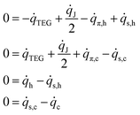 | (7) |
![[q with combining dot above]](https://www.rsc.org/images/entities/i_char_0071_0307.gif) J is the heat flux per unit area due to the Joule effect, and
J is the heat flux per unit area due to the Joule effect, and ![[q with combining dot above]](https://www.rsc.org/images/entities/i_char_0071_0307.gif) π,h and
π,h and ![[q with combining dot above]](https://www.rsc.org/images/entities/i_char_0071_0307.gif) π,c the heat exchanged per unit area at the hot and the cold side respectively due to the Peltier effect. The system of equations is thus found to be
π,c the heat exchanged per unit area at the hot and the cold side respectively due to the Peltier effect. The system of equations is thus found to be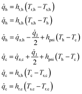 | (8) |
The heat dissipated per unit area due to the Joule effect is given by ![[q with combining dot above]](https://www.rsc.org/images/entities/i_char_0071_0307.gif) = nRpni2, in the formula
= nRpni2, in the formula
 | (9) |
![[q with combining dot above]](https://www.rsc.org/images/entities/i_char_0071_0307.gif) π,h = niπnp(Th) and
π,h = niπnp(Th) and ![[q with combining dot above]](https://www.rsc.org/images/entities/i_char_0071_0307.gif) π,c = niπnp(Tc) at the hot and the cold side respectively. From Kelvin's relations,25 substituting for the current, it follows that
π,c = niπnp(Tc) at the hot and the cold side respectively. From Kelvin's relations,25 substituting for the current, it follows that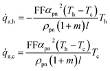 | (10) |
 | (11) |
 | (12) |
In the light of the given definitions, the non-linear system of thermoelectric equations is finally obtained:
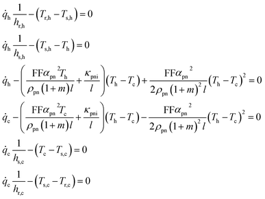 | (13) |
2.4 Linearized model
The non-linear model can be linearized by neglecting the Joule and the Peltier terms of eqn (14) in order to obtain simple closed forms of the power generated and the efficiency of energy conversion. In particular, while under small temperature differences, the Joule term, which scales according to (Th − Tc)2, is always much smaller than the Peltier and Fourier conduction terms, which scale like (Th − Tc)Th and (Th − Tc) respectively, and can thus be always safely disregarded; the Peltier terms can be discarded only if | (14) |
Therefore, under small temperature differences, the error of the linearized model essentially coincides with the error committed by discarding the Peltier terms, the latter depending on the device design and material thermoelectric properties. Under linear approximation, no thermal losses within the device due to thermoelectric conversion are considered and the outgoing heat flux at the cold reservoir equals the absorbed one from the hot reservoir. Therefore, Th − Tc is linearly related to the external temperature difference Tr,h − Tr,c by the following equation:
 | (15) |
 | (16) |
Co-optimization with respect to the thermocouple length and load resistance ratio is obtained for
 | (17) |
 | (18) |
![[p with combining tilde]](https://www.rsc.org/images/entities/i_char_0070_0303.gif) out can be further maximized with respect to Z alone by an appropriate choice of the leg section ratio. In particular, the thermocouple figure of merit is maximized for
out can be further maximized with respect to Z alone by an appropriate choice of the leg section ratio. In particular, the thermocouple figure of merit is maximized for | (19) |
 | (20) |
Therefore, when the thermoelectric properties of the p- and n-type legs are equal, the generated power is maximized for symmetric thermocouples, namely for Ap = An, while, when the thermoelectric properties of the p- and n-type legs are different, the power is maximized by properly tuning their section ratio according to eqn (19).
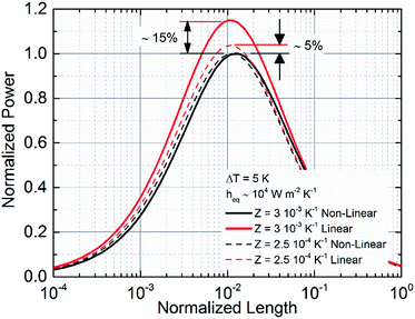
Direct comparison between the linear and the non-linear model at load matching (m = 1) is shown in Fig. 3 for ΔT = 5 K and good thermal coupling with the environment (heq. = 104 W m−2 K−1). The architecture considered is made of 525 μm thick silicon substrates with nominal thermal conductivity κSi = 140 W m−1 K−1, and vacuum insulation between thermocouples is supposed. Data are normalized with respect to the non-linear model and two different values of Z are considered, namely 3 × 10⁻³ K−1 and 2.5 × 10⁻⁴ K−1. As shown, the linear model is found to overestimate the power generated by more than 10% at load and thermal matching for Z = 3 × 10⁻³ K−1, but when thermocouples characterized by a smaller Z are considered, the differences between the models are rapidly smoothed out.
Although the linear model is shown to overestimate the performances of thermoelectric devices, it provides immediate and valuable information on device engineering and architecture designs from closed forms of power and efficiency. Nonetheless, the non-linear model should be preferred especially for high Z and when it is not computationally time consuming. In this work, the linear model will be first used to identify, from closed forms, requirements of the thermocouple figure of merit and device geometry needed to achieve a certain power output per unit area. Then, the non-linear model will be used to confirm predictions from the linear one for a series of different cases considering different families of potential applications.
3. Designing organic devices on flexible substrates
Flexible thermoelectric generators must preserve their electrical properties under mechanical stresses and deformations, and, at the same time, their mechanical properties must not be affected by temperature excursions. Therefore, an appropriate choice of both thermoelectric and substrate materials, which substantially diverge from those used in the fabrication of conventional rigid devices, is required. The analysis that follows involves the study of fundamental aspects of organic μTEG engineering considering typical materials implementable for the fabrication of flexible modules. The study is conducted by means of the linear model and is carried out with the aim to identify the conditions necessary for energy harvesting at the micro-scale by thin and lightweight thermoelectric generators. Two main fields of applications in the framework of IoT are considered, namely the one related to human body energy harvesting and the more general one dealing with networks of sensors and actuators for industrial and/or housing applications. The first scenario will be given the name “wearables”, the second one the more general name “networks”. Among the many variables distinguishing the two scenarios, since the model is for an infinite reservoir at fixed temperature, the external temperature difference represents a fundamental one. In the wearables scenario, devices for human body energy harvesting will be designed in order to be installed onto and/or integrated into clothes or directly on human skin. Therefore, the external temperature difference falling across the whole device is expected to be very small. In fact, while direct installation on skin could allow direct access to the skin temperature, clothes surrounding the generator will act as a thermal shield, significantly lowering the temperature of the external reservoir. On the other hand, while integration on clothes will allow direct heat exchanges with the environment, the insulating layer of the fabric will inevitably inhibit direct access to the warmer temperature of the skin, again limiting the effective temperature difference falling across the device, unless more elaborated TEGs based on knitted p- and n-type active fibers and/or coated fibers are adopted.26–28 Therefore, while an experimental study is required to determine the real temperature differences available for human body energy harvesting, in the absence of data it is reasonable to consider for modeling a very small external temperature difference, that is ∼2 K. On the other hand, in the networks scenario, μTEGs are designed to be implemented in industrial and housing environments, thus suffering from fewer constraints. When considered to harvest room temperature energy, they are supposed to operate under slightly larger temperature differences. Accordingly, in this work, the corresponding external temperature difference will be set equal to 5 K.3.1 On the equivalent heat transfer coefficient
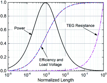
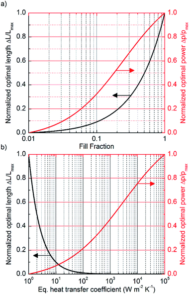
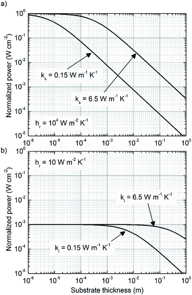
According to eqn (17), thermal matching is achieved corresponding to a certain thermocouple length, determined by the ratio between the effective thermal conductivity of the thermocouple unit and the equivalent heat transfer coefficient of the device, such that the right combination of the two allows maximizing the power generated corresponding to a certain desired length. Therefore, the intervals over which κpni and heq. are allowed to span represent key aspects of device engineering. The upper bound to the equivalent heat transfer coefficient heq. is determined by the thermally less conductive term entering the definition of heq.. Therefore, a competitive trend is established among materials, substrate thickness and the mechanisms of thermal coupling with the environment. In particular, depending on the mechanism of heat exchange, the thermal conductance at the reservoirs hr can be properly tuned to span a large interval, as widely discussed in the ESI.† In fact, direct mechanical contact between the device and the heat source/sink is such that hr > 105 W m−2 K−1; convection in the absence of radiation (i.e. small temperature differences) allows for hr ∼ 1 W m−2 K−1 from flat surfaces and hr ∼ 102 to 104 W m−2 K−1 from heat exchangers provided an appropriate choice of exchanger geometry and flow regime; hr ∼ 104 to 106 W m−2 K−1 is finally achievable even by liquid cooling, provided a right choice of mass flow and heat exchanger geometry. Evidently, in the case of cooling from heat exchangers, the joining between the device and the exchanger determines a finite thermal contact resistance. While this loss factor is generally negligible in the case of air cooling, it might not be as such in the case of liquid cooling where the thermal conductance of the joining could be smaller than the thermal conductance of the coupling with the environment. Therefore, under some circumstances, the thermal contact resistance arising from the joining may determine the superior limit to the equivalent heat transfer coefficient achievable, unless the exchanger is directly grown on top of the device.19 At the same time, the effective thermal conductivity of the thermocouple units κpni could span an interval corresponding to the difference between the average thermal conductivity of the thermocouple and the thermal conductivity of the insulator (generally corresponding to about one order of magnitude): in fact κpni = κpnFF + κi(1 − FF), and thus κpni goes from κpn when FF = 1 to κi when FF = 0. Therefore, the combination of heq. and κpni determines the thermocouple optimal length, from tens of centimeters for heq. ∼ 10 W m−2 K−1, down to a few micrometers for heq. ∼ 104 W m−2 K−1, ultimately addressing the need for different device fabrication technologies. Nevertheless, the fill fraction and the equivalent heat transfer coefficient directly affect also the power generated. The effect of independently tuning FF and heq. on the thermocouple optimal length and on the power output is determined according to eqn (17) and (18) and is shown in Fig. 4. The curves, which are normalized and are thus representative of a very general case, reveal that when κi ≠ 0 and once heq. is given, increasing the fill fraction allows the increase of the power generated only at the expense of much longer thermocouples. This effect does not occur when κi → 0 (and under conditions of low temperature, where heat exchange due to radiation is negligible), such is the case of vacuum insulation.24 In fact, under those conditions κpniApni = κpnApn, the maximum output power is independent of the fill fraction and the latter can be properly tuned without affecting the power generated. Therefore, decoupling the fill fraction from the power generated by vacuum encapsulation of the device is, when technologically feasible, a powerful method for tuning the thermocouples optimal length without affecting the maximum power generated. On the other hand, working on the heat transfer coefficient provides the opportunity to simultaneously increase the maximum output power and decrease the optimal length. However, while tuning the fill fraction enables the shifting of the optimal length and the power output by only one order of magnitude (depending on the average thermal conductivity of the thermocouple and of the insulator), working on heq. allows the shifting of the optimal length by many orders of magnitude, simultaneously increasing the power generated per unit area according to eqn (18). In the light of what has been discussed, increasing the equivalent heat transfer coefficient by an appropriate choice of substrate materials and thickness and by optimizing the thermal coupling with the environment represents the primary aspect to be focused on to simultaneously increase the power generated and reduce the thermocouple length, and thus the thermoelectric material usage. In order for the thermoelectric technology to be practically considered as potential primary battery technology, among many considerations, the whole energy balance has to be convenient. Therefore, considering the small amount of energy produced under small temperature differences (state of the art μTEGs harvest ∼0.5 mW cm−2 at load matching, under ΔT = 5 K, with efficiency close to 0.2%),8 cooling by fan, which consumes hundreds of mW, or liquid, which might require a pumping system if liquid is not provided otherwise, cannot be adopted and natural convection, or direct mechanical contact, represents the most likely solution to be considered for thermal coupling with the environment. However, the impact of the thermal coupling on the equivalent heat transfer coefficient assumes another connotation when considering the flexible substrates needed to realize flexible devices, such as poly(ethylene 2,6-naphthalate), poly(ethylene terephthalate) or poly(4,4′-oxydiphenylene-pyromellitimide), named PEN, PET and KAPTON respectively. In fact, these plastics, being highly thermally insulating (κ ∼ 0.1–0.2 W m−1 K−1), may pose a potential upper limit to the equivalent heat transfer coefficient regardless of the mechanism of thermal coupling with the environment, and thus, according to eqn (18), to the maximum generable power. Even more, according to eqn (17), they might pose an inferior limit to the optimal length, forbidding micro architectures from being efficient in certain environments. Considering, for instance, a symmetric device, with κs,c = κs,h ≈ 0.15 W m−1 K−1, namely the typical thermal conductivity of PET and PEN, then hs,h = hs,c ≈ 0.15/l W m−2 K−1, which corresponds to the interval 1.5 × 101 to 1.5 × 10⁵ W m−2 K−1 for 10−2 < l < 10−6 m. Therefore, when the heat exchange at the reservoirs is highly efficient, the thermal conductance of the substrates becomes the limiting factor to the equivalent heat transfer coefficient. On the other hand, when the thermal coupling with the environment is poor, such as the case of air cooling from flat surfaces, where even the radiative heat transfer at low temperatures becomes important (hr,c = hconvr,c + hradr,c ∼ 10 W m−2 K−1), the thickness of the substrates does not represent a limitation anymore. This observation is relevant for the wearables scenario (ΔT = 2 K), where flexibility and comfort are prerequisites to be satisfied: in this context massive heat exchangers cannot be installed, and air cooling from flat surfaces is the only cooling method possible and, regardless of the mechanism adopted for thermal coupling with the heat source, according to eqn (17), thermal matching is achieved for extremely long thermocouples (∼10 cm). These circumstances force engineers to design devices far from optimal architectures, demanding for high Z to compensate for such deficiency. Nevertheless, since in this case the thermal resistance between the substrates and the reservoirs dominates the equivalent heat transfer coefficient, relatively thick substrates can be implemented without affecting significantly the power generated. This, while in principle could facilitate the fabrication process and could allow for substrate engineering in order to improve heat exchange with the reservoirs, thus possibly increasing the corresponding heat transfer coefficients and pushing upwards the upper limit of the equivalent heat transfer coefficient, will limit flexibility and thus applicability to wearables. On the other hand, when considering the networks scenario (ΔT = 5 K), there are no constraints due to comfort, and heat exchangers can be installed accordingly to space availability, when direct mechanical contact with both the heat sink and source is not feasible. Under these circumstances the thermal coupling with the environment is good (hr > 103 W m−2 K−1) and the thermal conductance of the substrates does represent the limitation to heq.. Therefore, thin and thermally conductive substrates should be considered in the fabrication process to maximize the power generated, such as thin foils of Al2O3, having a thermal conductivity of about 6–7 W m−1 K−1 (data from Nanotherm Ltd) and a thickness thinner than 30 μm. In this case, the thermal resistance of the substrates becomes much smaller than the one of the interface between the hot substrate and the hot source, and the upper limit to the equivalent heat transfer coefficient is thus moved to the coupling with the reservoirs. Once the equivalent heat transfer coefficient is made bigger than 104 W m−2 K−1, the device optimal length enters in the micro region, and μTEGs become the ideal architecture for thermal energy harvesting.In Fig. 5 the effect of increasing the heat transfer coefficient of the substrates by spanning their thickness over six orders of magnitude is shown for a representative case with κpni = 0.4 W m−1 K−1. Two substrates characterized by two different thermal conductivities are considered, namely κs = 0.15 W m−1 K−1 and κs = 6.5 W m−1 K−1, and distinction is made between good and poor thermal coupling with the environment. Data are normalized with respect to the case of good thermal coupling and high thermal conductivity. In the case of poor thermal coupling with the environment, no appreciable differences in the power output are observed when the substrate thickness goes below 1 mm. On the other hand, when the thermal coupling with the environment is good, the power generated becomes strongly sensitive to the heat transfer coefficient of the substrates, and thus to their thickness. In the light of this discussion, since the higher the equivalent heat transfer coefficient, the higher the power generated, and since thin substrates are necessary to push the equivalent heat transfer coefficient up to the ultimate limit represented by the thermal contact resistance, thin substrates, needed to ensure flexible properties to the final device, are in all cases either beneficial or not detrimental.
3.2 On the thermocouple figure of merit
The thermoelectric efficiency factor Φ, in the formula15 | (21) |
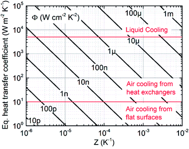 | ||
| Fig. 6 Thermoelectric efficiency factor calculated with the linear model and with FF = 0.5. According to eqn (22) and (25), tuning the fill fraction, the efficiency factor can be shifted by approximately one order of magnitude with respect to the value reported in the figure. The regions corresponding to liquid cooling, heat exchangers and flat surfaces are shown in order to identify the upper limit of heq. depending on the cooling mechanism adopted. | ||
3.3 On the thermoelectric unit characteristic dimensions
Power output is not the only device characteristic to be tuned at the design level. A second important parameter is the voltage generated under nominal operative conditions. In fact, in order for a TEG to become a primary battery source, the voltage generated under nominal conditions must reach the one delivered by batteries, at least 1.5 V. While a voltage–voltage converter in cascade to a thermoelectric generator could be used to compensate for small voltage and/or voltage fluctuations due to temperature difference fluctuations, efficiency losses must be minimized in order not to significantly affect the power delivered by the generator. This can be achieved only by designing TEGs to generate voltages close to application demands under nominal operative conditions. Therefore, according to technological resolution limits, the physical dimensions of the generator must be chosen in order to accommodate a number of thermocouples necessary to generate the desired voltage under specific external temperature conditions. According to the linear model, the number of thermocouples needed to generate the desired voltage Ṽ at load and thermal matching is equal to | (22) |
Therefore, the characteristic dimension of the thermocouple unit  needed to generate the voltage Ṽ on a surface whose extension is A is given by
  . In Fig. 7 the thermoelectric characteristic dimension
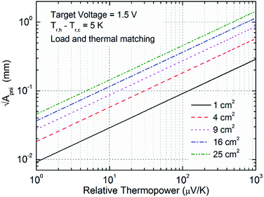
  at load and thermal matching is shown as a function of the relative thermopower of the thermocouples and as a function of device area. For instance, by choosing
  , in order to generate 1.5 V from a device occupying a superficial area smaller than 5 cm2, a relative thermopower higher than 100 μV K−1 is required. In contrast, if larger surfaces were available, smaller relative thermopower could satisfy the needs. Therefore, depending on fabrication technologies and thus thermoelectric unit resolution, and on the field of applications, more or less high relative thermopower is needed to target a desired voltage from a given surface. When considering air cooling from heat exchangers, the will of pursuing devices occupying the smallest surfaces is basically dictated by two reasons: the smaller the device, the larger the possibility of device implementation due to limited space needs; and the smaller the device, the smaller the heat exchangers required to dissipate the heat at the cold side. The latter aspect arises from considerations on module costs. It was in fact demonstrated that generators optimized with respect to cost per Watt are such that the overall fabrication costs are mainly due to heat exchangers.29,30 In the light of these observations, large flexible thermoelectric devices could suffer from much higher costs with respect to batteries when cooling is provided by heat exchangers. In contrast, exploitation of the heat source and sink by direct mechanical contact of both device substrates could represent a promising path for organic devices based on cost effective processing methods.
4. Materials for organic flexible devices
In the last few decades, the transport properties of organic materials have been widely studied and developed.31–35 They were found to be strongly sensitive to processing methods and conditions, which determine the morphology of the resulting sample, and to atmospheric composition and exposure, which could induce absorption/desorption of oxygen and moisture depending on the chemistry of the material.36 In addition, due to aggregation phenomena, as in the case of small molecules with large conjugated planes such as perylene diimide (PDI) derivatives,37 and/or due to preferential conduction of charge carriers along certain directions, as occurring in conjugated polymers along the polymer backbone, their transport properties were found to be strongly anisotropic with respect to the direction of growth,38–43 representing a fundamental aspect in thermoelectric device engineering. In fact, since material properties are affected by growth methods, and since the latter are correlated with device fabrication processes, thermoelectric generators with good performances can only be achieved by an appropriate combination of both materials and fabrication methods. While the in-plane thermoelectric properties of thin and thick films have been largely studied, there are only few reports on their corresponding cross-plane properties and, even more, there are just few examples of complete characterization of the transport properties of single samples of organic materials with respect to both directions.40,41,44 In Fig. 8, the room temperature thermopower and electrical conductivity of a series of doped organic materials belonging to different families are shown, where (+) and (−) denote p- and n-types respectively, (∥) and (⊥) distinguish between in-plane and cross-plane measurements from thin/thick films, and (O) measurements from bulk/single crystals. The list, which does not pretend to be comprehensive, does not take into account composites, nor organic–inorganic blends, and considers only data from contribution where distinction among transport directions was accurately made. In detail, the figure reports data from representative materials of hydrochloric acid-doped polyaniline (PANI:HCl),45 hexafluorophosphate doped polypyrrole (PPy:PF6),46 poly{N,N′-bis(2-octyl-dodecyl)-1,4,5,8-napthalenedicarboximide-2,6-diyl]-alt-5,5′-(2,2′-bithiophene)} doped by dihydro-1H-benzimidazol-2-yl (P(NDIOD-T2):N-DBI),47 poly(metal 1,1,2,2-ethenetetrathiolate)s (poly[…]),48 poly(3,4-ethylenedioxythiophene)tosylate (PEDOT:Tos),49 poly(3,4-ethylenedioxythiophene)polystyrene sulfonate (PEDOT:PSS),41 poly(3-hexylthiophene) doped by triflimide anions (P3HT:Fe(TFSI)3)44 and by hexafluorophosphate (P3HT:PF6),50 tetrathiofulvalinium tetracyanoquinodimethane charge transfer complex (TTF-TCNQ),51,52 pentacene doped by 2,3,5,6-tetrafluoro-7,7,8,8-tetracyanoquinodimethane (PC:F4TCNQ),53 fullerene doped by dimetal complexes of chromium and tungsten with the anion of 1,3,4,6,7,8-hexahydro-2H-pyrimido[1,2-a]pyrimidine (hpp) (C60:Cr2(hpp) and C60:W2(hpp)),54 and self-doped PDI.37 It has to be noted that the thermopower of PEDOT:PSS and that of P3HT:Fe(TFSI)3 were found to be almost isotropic with respect to the plane of growth, while their corresponding electrical conductivities were not. Despite the amount of data available on thermopower and electrical conductivity, the thermal conductivity (not shown) was measured only for a limited number of the materials reported. In particular, concerning polymers, it was found to be lower than 1 W m−1 K−1 in every case but PEDOT:Tos, the latter revealing an in-plane higher value approximately equal to 1.5 W m−1 K−1 at room temperature.49 These observations are ascribed to the intrinsic disordered nature of organic matter and to their relatively low electrical conductivity (<500 S cm−1). In fact, while the former is responsible for low phonon contribution to the thermal conductivity, the latter is such that, even in the worst case in which the Wiedemann–Franz law was valid (as was shown for the in-plane transport properties of PEDOT:PSS),40 the electronic contribution to the thermal conductivity would be also small, leading to an overall small thermal conductivity. Fig. 8 shows the validity of the theoretical inverse trend between the thermopower and the electrical conductivity also in organic materials (a detailed study of the topic is given in the recent studies of Russ et al.35 and Kang et al.55), thus representing a powerful tool to determine the optimal conductivity range which maximizes the power factor of this class of materials.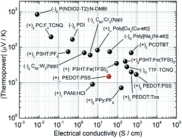 | ||
| Fig. 8 Thermopower module versus electrical conductivity of representative materials belonging to different families of organic materials. | ||
5. Case studies
The non-linear model is here used to study a series of different cases involving organic flexible thermoelectric generators with vertical architectures. The devices considered are made of 30 μm thick PEN substrates, and the following thermocouples are considered, with reference to the materials reported in Section 4.: PEDOT:PSS/Ag, PEDOT:PSS/PDI, P+/N+ and P++/N++, where the latter two are hypothetical thermocouples characterized by Z+ = 10−4 K−1 (ZT = 0.03) and Z++ = 10−2 K−1 (ZT = 3). PEDOT:PSS41 and PDI37 were chosen, among the materials reported in Fig. 8, on the basis of their assessed processability from solution, while silver was chosen as substitutive material for the n-type leg, a choice which reflects recent attempts of module fabrication by means of short circuiting p-type legs with silver stripes due to the current scarcity of easily processable, air stable, and highly doped n-type organic conductors.56 Finally, P+/N+ and P++/N++ thermocouples were chosen imagining an improvement of the thermoelectric properties of organic conductors in the near future and in order to validate the result of the linear model, according to which Z > 10−4 K−1 (ZT > 0.03) and Z > 10−2 K−1 (ZT > 3) are demanded to generate sufficient power for applications in the field of networks and wearables respectively. PEN substrates were preferred to the more thermally conductive Al2O3 flexible ones due to PEN relatively lower costs. Their thickness was set equal to 30 μm in order not to make the heat transfer coefficient of the substrates to dominate over the equivalent heat transfer coefficient and to preserve high levels of flexibility. Finally, electrical insulation between thermocouple legs was provided by SU-8 photoresist, following the first practical demonstration of flexible generators with a vertical architecture.57,58 The thermoelectric properties of the materials considered are reported in Table 1. While the cross-plane thermoelectric properties of PEDOT:PSS are available in the literature,41 only the in-plane properties of the solution processable PDI are reported.47 In the absence of specific data, its thermoelectric coefficients were considered isotropic and, due to its low electrical conductivity and disordered nature, its thermal conductivity was set equal to that of common insulating plastic, namely 0.2 W m−1 K−1.The simulations distinguish between three cases (5.1)–(5.3), belonging to the wearables and the networks scenario, characterized by different conditions of thermal coupling with the environment, and thus being representative of a series of different potential applications. In detail:
5.1 Wearables scenario
The heat source is provided by direct mechanical contact with the skin, while the heat sink is provided by air cooling from flat surfaces under natural convection. Since the thermal conductivity of human skin is affected by a number of variables such as the hydration level, composition, emotional status, level of sweat and many other factors, hr,h is extremely variable and requires experimental evaluations. Following the study of M. Lossec et al.,21 according to which 10 < hskinr < 100 W m−2 K−1, hr,h was set equal to an intermediate value, namely 50 W m−2 K−1. The heat transfer coefficient at the cold side is given by the sum of the convective and radiative terms, the latter being not negligible under natural convection from flat surfaces, and it was set equal to 10 W m−2 K−1.5.2 Networks scenario 1
The heat source and the heat sink are both provided by direct mechanical contact with the hot source and sink respectively. Therefore hr,h = hr,c = 105 W m−2 K−1 and the generator can be thought as some sort of thermal insulator between two highly conductive media. This case has to be intended representative for all those situations where the heat transfer coefficient at the reservoirs is much higher than the one of the substrates.5.3 Networks scenario 2
The heat source is provided by direct mechanical contact with the hot source, while the heat sink is provided by air cooling from heat exchangers under natural convection. Accordingly, hr,h and hr,c are set equal to 105 W m−2 K−1 and 103 W m−2 K−1 respectively. This case is representative of a variety of applications in industrial and/or housing self-regulating environments, where sensing, actuation and communication must be provided by distributed and renewable energy sources.In each case, the fill fraction was tuned from 0.01 to 0.99 in order to evaluate the impact of this additional degree of freedom on device performances, and the ratio Ap/An was evaluated under symmetric (Ap = An) and optimal (see eqn (19)) conditions. Because of plausible technological limits, the thermocouple leg diameter was chosen equal to 100 μm leading to a thermocouple unit characteristic dimension slightly bigger than 125 μm in the limit of FF = 0.99. This choice allows the accommodation of a number of thermocouples per cm2 in the interval 60–6000 for the fill fraction spanning the range 0.01 < FF < 0.99, under the condition Ap = An.
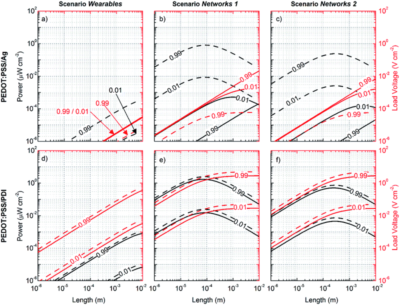
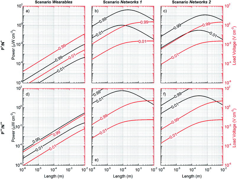
In Fig. 9 and 10 the simulated power and voltage generated per unit area are shown as a function of the thermocouple thickness, which is allowed to span the interval 1 μm to 1 cm, according to the conditions established by the three cases discussed. While Fig. 9 represents the cases for actually available materials, namely PEDOT:PSS, Ag and PDI, Fig. 10 represents the cases for hypothetical thermocouples made of P+, P++, N+ and N++ hypothetical materials. Continuous and dashed lines are used for the symmetric and the optimized geometry respectively. In every case and for each choice of thermocouple, the power and the voltage generated are observed to be an increasing function of Z and FF, and the maximum power is obtained corresponding to the thermal matching conditions, the latter being a decreasing function of the thermal coupling with the environment, as expected. While in the two networks scenarios, by geometry optimization, thermal matching is achieved for relatively short thermocouples (<500 μm), in the wearables scenario, due to poor thermal coupling with the environment, thermal matching is always achieved for very long thermocouples (>1 cm) irrespective of the thermal conductivity of the thermocouple unit, and the power generated remains always largely below 1 μW per cm2. This happens even in the case of hypothetical thermocouples characterized by Z = 10−2 K−1 (ZT = 3), namely a value approximately two times higher than that of the best thermocouple known so far for room temperature applications.59 In order to generate tens of μW per cm2 at thermocouple lengths compatible with micro architectures (<500 μm) and under the conditions of poor thermal coupling with the environment (heq. ∼ 10 W m−2 K−1), according to eqn (17), κpni must be in the order of 10−3 W m−1 K−1. Therefore, even considering the case of thermoelectric materials characterized by extremely low thermal conductivity κp = κn = 0.2 W m−1 K−1, thermocouple insulation cannot be provided by solid state matter, and vacuum encapsulation must be considered (air is not enough since κi ≅ 0.02 W m−1 K−1 at 1 atmosphere). In fact, when κi = 0, κpni = κpnFF and for FF < 0.025 thermal matching is achieved in the micro region. However reducing the fill fraction also reduces the power generated, and thus the minimum Z required is shifted up by approximately one order of magnitude, namely Z > 10−1 K−1 (ZT > 30) and, even in the case of larger surfaces (i.e. 100 cm2), the required figure of merit does not go below 10−3 K−1 (ZT = 0.3). This lays the emphasis on the need for more efficient coupling with the environment. In fact, unless a significant breakthrough in organic thermoelectric materials is obtained in the near future, or novel device architectures are proposed for the purpose,26,27 conventional architectures adopting organic materials will hardly find application in the wearables scenario. In contrast, novel architectures directly knitted into clothes could make use of the much thicker structures granted by cloth thickness (few mm) and could exploit the temperature gradient established by the clothes themselves. Novel methods of investigation and modeling of these architectures are required to estimate the potentiality of the technology in this framework. For instance, considering the temperature difference sustainable by trekking and diving suits, sport garments look like promising niches for the implementation of thermoelectric technology in wearable applications. In these cases, thermoelectrics could provide an effective way to power sensors dedicated to monitor the health of the user. In fact, despite the fact that issues concerning thermal coupling with the environment are not solved, thermal matching conditions are achieved for κpni ∼ 0.01, which can be obtained even by air insulation and appropriate fill fraction tuning. In this case, using larger devices, the inefficiency of thermal coupling can be well compensated and, with reference to Fig. 6, Z > 10−4 K−1 (ZT > 0.03) could be sufficient for many purposes. It is worth underlining that these are hypotheses which require practical assessment to be validated.
On the other hand, in the two networks scenarios, due to the better thermal coupling with the environment, micro architectures are more appropriate and power and voltage targets are much more easily achievable by proper geometrical tuning and material choice. With reference to Fig. 9b and c, it is interesting how geometrical optimization of the couple PEDOT:PSS/Ag leads to a shift of almost 6 orders of magnitude in the power generated per unit area, up to almost 1 μW per cm2 corresponding to the thermal matching conditions of the optimized structure. This is a consequence of the shifting of the thermal matching length towards shorter legs, and is ascribed to the significant increase of the sectional area of the PEDOT:PSS leg (the diameter shifts from 100 μm to 6.7 mm) with respect to the one of silver. However, consequently the number of thermocouples per cm2 is strongly reduced (to approximately 0.03 per cm2), and so is the voltage delivered to the load, which drops down in the order of tens of pV per cm2, namely values of no practical use.
With reference to Fig. 9e and f, the couple PEDOT:PSS/PDI is not affected by geometrical optimization as much as the previous one is. This follows from the smaller difference between the thermal and electrical conductivities of the constituent materials. However, while the voltage delivered to the load can be pushed up to 1 V per cm2 by tuning the fill fraction, the power generated never exceeds 1 μW per cm2, even in the unrealistic case of FF = 0.99. Comparison between the couples PEDOT:PSS/Ag and PEDOT:PSS/PDI reveals how fundamental the improvement of the thermoelectric properties of both p- and n-type legs becomes in order to increase the power and voltage generated, and makes micro architectures suitable for the purpose.
Once the inadequacy of the present materials to address technological requirements has been assessed, with reference to Fig. 10b, c, e and f, the networks scenarios are studied under the hypothesis of thermocouples having Z > 10−4 K−1 (ZT > 0.03) and Z > 10−2 K−1 (ZT > 3) respectively, the former being the minimum figure of merit required for IoT applications according to the linear model. The simulations confirm that 10−4 K−1 (ZT > 0.03) is the minimum value for the figure of merit Z to be targeted for thermoelectric technology to be implemented in this sector.
6. Conclusions and perspectives
A non-linear model for thermoelectric devices operating under low temperature differences was introduced. A linearized model was then derived and discussed, and comparison between the two was made, highlighting the importance of the linear model to extract approximate information on device engineering from analytical expressions of power and efficiency. The linear model was extensively used to discuss two main scenarios of applicability of organic, flexible thermoelectric generators, namely wearables (ΔT ∼ 2 K) and networks (ΔT ∼ 5 K), the latter dealing with energy supply to low power devices belonging to industrial and housing networks, and both embracing a series of potential applications in the field of the Internet of Things. Among the distinguishing parameters, the thermal coupling with the environment was identified as a fundamental one to discriminate between different families of applications, and its impact on the equivalent heat transfer coefficient was discussed in connection with the heat transfer coefficient of plastic substrates. The latter was recognized as the upper limit to the equivalent heat transfer coefficient in the case of good thermal coupling with the environment (hr > 103 W m−2 K−1), thus demanding thin and highly conductive substrates to increase the effective temperature difference falling across the thermocouples and so the power generated per unit area. In contrast, in the case of poor thermal coupling with the environment (∼10 W m−2 K−1), the thermal coupling itself was identified as the upper limit to the equivalent heat transfer coefficient, and thus to the power generated. Since the equivalent heat transfer coefficient enters also in the definition of thermal matching, its value was found determinant to address the optimal length of the thermocouples, and consequently the architecture of the device and the fabrication methods. In particular, micro thermoelectric generators were found to be the ideal architectures for energy harvesting at the microscale only under conditions which lead to high equivalent heat transfer coefficients (heq. > 103 W m−2 K−1), namely good thermal coupling and thin substrates, the former being achievable by implementing heat exchangers and/or providing direct mechanical contact between the device and the heat source and sink. Therefore, in order for conventional micro architectures to be implemented in wearable applications, good thermal coupling with the environment and thin plastic substrates are required in order to keep low the equivalent heat transfer coefficient and thus the thermocouple length at which thermal matching conditions are achieved. Unfortunately, unless novel architectures are designed and introduced, conventional architectures in the field of wearables do not allow for good thermal coupling with the environment, thus pushing the ideal thickness up to a few cm and ultimately compromising the requirements of comfort and flexibility.Material thermoelectric properties were then discussed in direct relation with the equivalent heat transfer coefficient. By means of the thermoelectric efficiency factor, the minimum requirement of Z was estimated on the basis of the power to be generated per unit area, on the external temperature difference available, and on the mechanism of thermal coupling with the environment. Approximately, they were identified as Z > 10−4 K−1 (ZT > 0.03) and Z > 10−2 K−1 (ZT > 3) for the two scenarios of networks and wearables respectively.
The characteristic dimensions of the thermoelectric units were analyzed in direct relation with the voltage generated per unit area. The study unveiled the necessity of a high relative thermopower (>100 μV K−1) and/or technological breakthrough to reduce the minimum size feature, in order to deliver, under nominal operative conditions, voltages competitive to the ones delivered by batteries (1.5 V) from devices occupying relatively small surfaces (<5 cm2).
A series of simulations were then conducted, using the non-linear model, on a series of devices made of different thermocouples. Available materials were considered, and so were fictitious ones in order to assess forecasts from the linear model. The simulations confirmed the assumptions on material properties and thermal management needs. In particular, while for wearable devices Z > 10−2 K−1 (ZT > 3) was found to be necessary to generate tens of μW from 1 cm2, less stringent demands were found necessary for IoT applications in the field of industrial and housing networks, namely Z > 10−4 K−1 (ZT > 0.03). However, these requirements of the figure of merit were found to be compatible with micro architectures only in the case of good thermal coupling with the environment. In the case of wearables, where the thermal coupling is poor, in order to generate tens of μW per cm2 from μTEGs based on conventional micro architectures, thermocouples with extraordinary thermoelectric properties (Z > 0.1 K−1 (ZT > 30)) are necessary. This requirement, being more than one order of magnitude far beyond the figure of merit of the best thermocouple for room temperature applications ever discovered,59 is unlikely to be achieved in the short term. However, increasing the extension of the surface up to 100 cm2 allows the reduction of the requirements of the figure of merit, which shifts down to approximately 10−3 K−1 (ZT = 0.3), a more likely value to be achieved in the near future. Novel and innovative architectures of TEGs directly knitted into clothes could even shift the requirements of the figure of merit down to 10−4 K−1 (ZT = 0.03) in order to generate few μW from a 100 cm2 surface. Considering the steady advances in the synthesis of more and more performing conjugated organic materials during the last two decades,31,33,60–70 this last requirement represents a more probable and promising target for future applications of organic thermoelectrics in this sector, addressing the needs for further studies of innovative architectures.
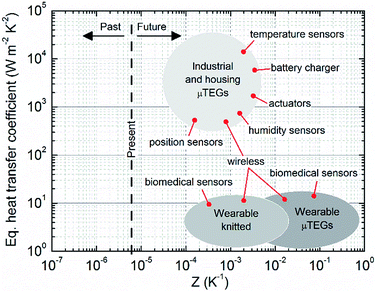
The results achieved within this work allow defining a potential roadmap towards future applications of organic thermoelectrics. The roadmap is shown in Fig. 11, where, given the characteristic equivalent heat transfer coefficient, the families of applications are shown as functions of the necessary thermocouple figure of merit. Target power was set equal to a few μW, and clouds surrounding each family were drawn to take into account for different fill fractions and/or device surface extension (in the interval 1–100 cm2). The line of the present is established considering the couple PEDOT:PSS/PDI, namely the best thermocouple made of actual materials processable from solution. Despite the fact that no applications can be addressed by the present technology, slight improvements of solution processable thermoelectric materials could allow for practical applications in the field of industrial and housing devices, such as movement sensors for alarm systems, position sensors, temperature and humidity sensors, general industrial process sensors, actuators for self-regulating environments and battery chargers from waste heat energy conversion, to name a few. On the other hand, IoT applications in the field of wearables demand innovative architectures, such as the already discussed knitted ones, in order to concretely integrate the generators into clothes and exploit increased thickness and larger surfaces to reach power requirements under poor thermal coupling and plausible materials in the near future. If novel architectures demonstrate to be effective, among the variety of potential applications, those belonging to the biomedical sector will be among the most promising: smart clothes capable of health monitoring will become feasible and collection of signals among millions of users could make available a large set of data from which, by means of big data analysis, a deeper understanding of human disease causes will be possible, potentially leading towards a more effective disease prevention.
As a closing remark, it has to be noted that, so far, the cross-plane thermoelectric properties of organic materials have received far less attention than their in-plane ones. Since the direction of the thermal and electric transport depends on the architecture of the generator, and since anisotropic thermoelectric properties are not only possible but even likely in many organic systems, these anisotropies should be accurately investigated in the near future. This will allow forecasting, by modeling, more accurate performances and identifying, with a higher degree of confidence, potential fields of applicability of the thermoelectric technology based on flexible materials.
References
- D. M. Rowe, CRC handbook of thermoelectrics, CRC press, Boca Raton, 2006 Search PubMed.
- L. E. Bell, Science, 2008, 321, 1457–1461 CrossRef CAS PubMed.
- G. J. Snyder and E. S. Toberer, Nat. Mater., 2008, 7, 105–114 CrossRef CAS PubMed.
- M. S. Dresselhaus, G. Chen, M. Y. Tang, R. G. Yang, H. Lee, D. Z. Wang, Z. F. Ren, J.-P. Fleurial and P. Gogna, Adv. Mater., 2007, 19, 1043–1053 CrossRef CAS.
- D. Briand, E. Yeatman, S. Roundy, O. Brand, G. K. Fedder, C. Hierold, J. G. Korvink and O. Tabata, Micro Energy Harvesting, John Wiley & Sons, 2015, vol. 12 Search PubMed.
- V. Mayer-Schönberger and K. Cukier, Big data: a revolution that will transform how we live, work, and think, 2013 Search PubMed.
- S. Greengard, The internet of things, The MIT Press, 2015 Search PubMed.
- H. Bottner, J. Nurnus, A. Schubert and F. Volkert, in 2007 26th International Conference on Thermoelectrics, IEEE, 2007, pp. 306–309 Search PubMed.
- B. P. Kauf, M. Gmbh and P. Kauf, Perpetuum, 2014, 11, 18–19 Search PubMed.
- M. Kaltenbrunner, M. S. White, E. D. Głowacki, T. Sekitani, T. Someya, N. S. Sariciftci and S. Bauer, Nat. Commun., 2012, 3, 770 CrossRef PubMed.
- M. S. White, M. Kaltenbrunner, E. D. Głowacki, K. Gutnichenko, G. Kettlgruber, I. Graz, S. Aazou, C. Ulbricht, D. A. M. Egbe, M. C. Miron, Z. Major, M. C. Scharber, T. Sekitani, T. Someya, S. Bauer and N. S. Sariciftci, Nat. Photonics, 2013, 7, 811–816 CrossRef CAS.
- M. Kaltenbrunner, T. Sekitani, J. Reeder, T. Yokota, K. Kuribara, T. Tokuhara, M. Drack, R. Schwödiauer, I. Graz, S. Bauer-Gogonea, S. Bauer and T. Someya, Nature, 2013, 499, 458–463 CrossRef CAS PubMed.
- D. H. Meadows, J. Randers and D. L. Meadows, The limits to growth: the 30-year update, Chelsea Green Pub. Co, 2004 Search PubMed.
- A. Chen, D. Madan, P. K. Wright and J. W. Evans, J. Micromech. Microeng., 2011, 21, 104006 CrossRef.
- W. Glatz, E. Schwyter, L. Durrer and C. Hierold, J. Microelectromech. Syst., 2009, 18, 763–772 CrossRef CAS.
- K. Yazawa and A. Shakouri, J. Appl. Phys., 2012, 111 DOI:10.1063/1.3679544.
- N. Wojtas, L. Rüthemann, W. Glatz and C. Hierold, Renew. Energy, 2013, 60, 746–753 CrossRef.
- N. Wojtas, E. Schwyter, W. Glatz, S. Kühne, W. Escher and C. Hierold, Sens. Actuators, A, 2012, 188, 389–395 CrossRef CAS.
- N. Wojtas, M. Grab, W. Glatz and C. Hierold, J. Electron. Mater., 2013, 42, 2103–2109 CrossRef CAS.
- M. T. Dunham, M. T. Barako, S. LeBlanc, M. Asheghi, B. Chen and K. E. Goodson, Energy, 2015, 93, 2006–2017 CrossRef.
- M. Lossec, B. Multon, H. Ben Ahmed and C. Goupil, Eur. Phys. J.: Appl. Phys., 2010, 52, 11103 CrossRef.
- G. Fraisse, J. Ramousse, D. Sgorlon and C. Goupil, Energy Convers. Manage., 2013, 65, 351–356 CrossRef.
- Y. Apertet, H. Ouerdane, O. Glavatskaya, C. Goupil and P. Lecoeur, EPL, 2012, 97, 28001 CrossRef.
- K. Yazawa and A. Shakouri, Environ. Sci. Technol., 2011, 45, 7548–7553 CrossRef CAS PubMed.
- C. A. Domenicali, Rev. Mod. Phys., 1954, 26, 237 CrossRef.
- J. A. Lee, A. E. Aliev, J. S. Bykova, M. J. de Andrade, D. Kim, H. J. Sim, X. Lepró, A. A. Zakhidov, J.-B. Lee, G. M. Spinks, S. Roth, S. J. Kim and R. H. Baughman, Adv. Mater., 2016, 28, 5038–5044 CrossRef CAS PubMed.
- Y. Du, K. Cai, S. Chen, H. Wang, S. Z. Shen, R. Donelson and T. Lin, Sci. Rep., 2015, 5, 6411 CrossRef CAS PubMed.
- S. J. Kim, J. H. We and B. J. Cho, Energy Environ. Sci., 2014, 7, 1959 CAS.
- S. K. Yee, S. LeBlanc, K. E. Goodson and C. Dames, Energy Environ. Sci., 2013, 6, 2561 Search PubMed.
- S. Leblanc, S. K. Yee, M. L. Scullin, C. Dames and K. E. Goodson, Renewable Sustainable Energy Rev., 2014, 32, 313–327 CrossRef CAS.
- Q. Zhang, Y. Sun, W. Xu and D. Zhu, Adv. Mater., 2014, 26, 6829–6851 CrossRef CAS PubMed.
- Y. Chen, Y. Zhao and Z. Liang, Energy Environ. Sci., 2015, 8, 401–422 CAS.
- O. Bubnova and X. Crispin, Energy Environ. Sci., 2012, 5, 9345–9362 CAS.
- N. Dubey and M. Leclerc, J. Polym. Sci., Part B: Polym. Phys., 2011, 49, 467–475 CrossRef CAS.
- B. Russ, A. Glaudell, J. J. Urban, M. L. Chabinyc and R. A. Segalman, Nat. Rev. Mater., 2016, 1, 16050 CrossRef CAS.
- J. Huang, P. F. Miller, J. C. De Mello, A. J. De Mello and D. D. C. Bradley, Synth. Met., 2003, 139, 569–572 CrossRef CAS.
- B. Russ, M. J. Robb, F. G. Brunetti, P. L. Miller, E. E. Perry, S. N. Patel, V. Ho, W. B. Chang, J. J. Urban, M. L. Chabinyc, C. J. Hawker and R. A. Segalman, Adv. Mater., 2014, 26, 3473–3477 CrossRef CAS PubMed.
- A. M. Nardes, M. Kemerink and R. A. J. Janssen, Phys. Rev. B: Condens. Matter Mater. Phys., 2007, 76, 85208 CrossRef.
- H. Sirringhaus, P. J. Brown, R. H. Friend, M. M. Nielsen, K. Bechgaard, B. M. W. Langeveld-Voss, A. J. H. Spiering, R. A. J. Janssen, E. W. Meijer, P. Herwig and D. M. de Leeuw, Nature, 1999, 401, 685–688 CrossRef CAS.
- J. Liu, X. Wang, D. Li, N. E. Coates, R. A. Segalman and D. G. Cahill, Macromolecules, 2015, 48, 585–591 CrossRef CAS.
- Q. Wei, M. Mukaida, K. Kirihara and T. Ishida, ACS Macro Lett., 2014, 3, 948–952 CrossRef CAS.
- L. H. Jimison, M. F. Toney, I. McCulloch, M. Heeney and A. Salleo, Adv. Mater., 2009, 21, 1568–1572 CrossRef CAS.
- S. N. Patel and M. L. Chabinyc, J. Appl. Polym. Sci., 2016 DOI:10.1002/app.44403.
- S. Qu, Q. Yao, L. Wang, Z. Chen, K. Xu, H. Zeng, W. Shi, T. Zhang, C. Uher and L. Chen, NPG Asia Mater., 2016, 8, e292 CrossRef CAS.
- J. Li, X. Tang, H. Li, Y. Yan and Q. Zhang, Synth. Met., 2010, 160, 1153–1158 CrossRef CAS.
- D. S. Maddison, J. Unsworth and R. B. Roberts, Synth. Met., 1988, 26, 99–108 CrossRef CAS.
- R. A. Schlitz, F. G. Brunetti, A. M. Glaudell, P. L. Miller, M. A. Brady, C. J. Takacs, C. J. Hawker and M. L. Chabinyc, Adv. Mater., 2014, 26, 2825–2830 CrossRef CAS PubMed.
- Y. Sun, P. Sheng, C. Di, F. Jiao, W. Xu, D. Qiu and D. Zhu, Adv. Mater., 2012, 24, 932–937 CrossRef CAS PubMed.
- A. Weathers, Z. U. Khan, R. Brooke, D. Evans, M. T. Pettes, J. W. Andreasen, X. Crispin and L. Shi, Adv. Mater., 2015, 27, 2101–2106 CrossRef CAS PubMed.
- Y. Xuan, X. Liu, S. Desbief, P. Leclère, M. Fahlman, R. Lazzaroni, M. Berggren, J. Cornil, D. Emin and X. Crispin, Phys. Rev. B: Condens. Matter Mater. Phys., 2010, 82, 1–9 CrossRef.
- P. M. Chaikin, J. F. Kwak, T. E. Jones, A. F. Garito and A. J. Heeger, Phys. Rev. Lett., 1973, 31, 601–604 CrossRef CAS.
- G. A. Thomas, D. E. Schafer, F. Wudl, P. M. Horn, D. Rimai, J. W. Cook, D. A. Glocker, M. J. Skove, C. W. Chu, R. P. Groff, J. L. Gillson, R. C. Wheland, L. R. Melby, M. B. Salamon, R. A. Craven, G. De Pasquali, A. N. Bloch, D. O. Cowan, V. V. Walatka, R. E. Pyle, R. Gemmer, T. O. Poehler, G. R. Johnson, M. G. Miles, J. D. Wilson, J. P. Ferraris, T. F. Finnegan, R. J. Warmack, V. F. Raaen and D. Jerome, Phys. Rev. B: Condens. Matter Mater. Phys., 1976, 13, 5105–5110 CrossRef CAS.
- K. Harada, M. Sumino, C. Adachi, S. Tanaka and K. Miyazaki, Appl. Phys. Lett., 2010, 96, 253304 CrossRef.
- T. Menke, D. Ray, J. Meiss, K. Leo and M. Riede, Appl. Phys. Lett., 2012, 100, 93304 CrossRef.
- S. Dongmin Kang and G. Jeffrey Snyder, Nat. Mater., 2016 DOI:10.1038/nmat4784.
- R. R. Søndergaard, M. Hösel, N. Espinosa, M. Jørgensen and F. C. Krebs, Energy Sci. Eng., 2013, 1, 81–88 CrossRef.
- W. Glatz, S. Muntwyler and C. Hierold, Sens. Actuators, A, 2006, 132, 337–345 CrossRef CAS.
- O. Bubnova, Z. U. Khan, A. Malti, S. Braun, M. Fahlman, M. Berggren and X. Crispin, Nat. Mater., 2011, 10, 429–433 CrossRef CAS PubMed.
- M. W. Gaultois, T. D. Sparks, C. K. H. Borg, R. Seshadri, W. D. Bonificio and D. R. Clarke, Chem. Mater., 2013, 25, 2911–2920 CrossRef CAS.
- M. Caironi and Y.-Y. Noh, Large area and flexible electronics, Wiley-VCH, 2015 Search PubMed.
- A. Marrocchi, A. Facchetti, D. Lanari, C. Petrucci and L. Vaccaro, Energy Environ. Sci., 2016, 9, 763–786 CAS.
- D. Venkateshvaran, M. Nikolka, A. Sadhanala, V. Lemaur, M. Zelazny, M. Kepa, M. Hurhangee, A. J. Kronemeijer, V. Pecunia and I. Nasrallah, et al. , Nature, 2014 DOI:10.1038/nature13854.
- S. Holliday, J. E. Donaghey and I. McCulloch, Chem. Mater., 2014, 26, 647–663 CrossRef CAS.
- C. B. Nielsen, M. Turbiez and I. McCulloch, Adv. Mater., 2013, 25, 1859–1880 CrossRef CAS PubMed.
- B. Sun, W. Hong, Z. Yan, H. Aziz and Y. Li, Adv. Mater., 2014, 2636–2642 CrossRef CAS PubMed.
- M. Sommer, J. Mater. Chem. C, 2014, 2, 3088–3098 RSC.
- N.-K. Kim, S. Jang, G. Pace, M. Caironi, W.-T. Park, D. Khim, J. Kim, D. Kim and Y. Noh, Chem. Mater., 2015, 27, 8345–8353 CrossRef CAS.
- M. J. Sung, A. Luzio, W.-T. Park, R. Kim, E. Gann, F. Maddalena, G. Pace, Y. Xu, D. Natali, C. de Falco, L. Dang, C. R. McNeill, M. Caironi, Y.-Y. Noh and Y.-H. Kim, Adv. Funct. Mater., 2016, 26, 4984–4997 CrossRef CAS.
- K. J. Baeg, M. Caironi and Y. Y. Noh, Adv. Mater., 2013, 25, 4210–4244 CrossRef CAS PubMed.
- O. Bubnova, Z. U. Khan, H. Wang, S. Braun, D. R. Evans, M. Fabretto, P. Hojati-Talemi, D. Dagnelund, J. Arlin, Y. H. Geerts, S. Desbief, D. W. Breiby, J. W. Andreasen, R. Lazzaroni, W. M. Chen, I. Zozoulenko, M. Fahlman, P. J. Murphy, M. Berggren and X. Crispin, Nat. Mater., 2013, 13, 190–194 CrossRef PubMed.
Footnote |
| † Electronic supplementary information (ESI) available. See DOI: 10.1039/c6se00028b |
| This journal is © The Royal Society of Chemistry 2017 |


