Optimization of performance and long-term stability of p-type dye-sensitized solar cells with a cycloruthenated dye through electrolyte solvent tuning†
Received
1st February 2017
, Accepted 7th March 2017
First published on 7th March 2017
Abstract
p-Type dye sensitized solar cells (DSCs) have been assembled using the structurally unrefined, zwitterionic cyclometallated ruthenium dye [Ru(bpy)2(H1)] (H31 = (4-(2-phenylpyridin-4-yl)phenyl)phosphonic acid) in combination with FTO/NiO photocathodes and an I3−/I−/acetonitrile (AN) electrolyte. Values of the short-circuit current density (JSC) = 4.06 mA cm−2, open-circuit voltage (VOC) = 95 mV and photoconversion efficiency (η) = 0.139% are the highest achieved for state-of-the-art cyclometallated ruthenium dyes in p-type DSCs; data are confirmed using duplicate devices. JSC values are higher than those observed for the standard dye P1, and electrochemical impedance spectroscopy (EIS) shows that DSCs with [Ru(bpy)2(H1)] exhibit a both a lower transport resistance (Rt) and recombination resistance (Rrec) than DSCs with P1. Changing the electrolyte solvent from AN to propionitrile (PN), valeronitrile (VN), 3-methoxypropionitrile (MPN) or N-methylpyrrolidone (NMP) confirms a dependence of JSC on solvent in the order AN > PN > MPN > VN > NMP, whilst VOC follows the trend VN > PN > MPN > AN > NMP. The opposing trends in JSC and VOC lead to only a small drop in the overall η values for PN versus AN. EIS measurements revealed that although PN has a higher resistance to recombination reactions than AN, it also exhibits an increased amount of trapped charge carriers, leading to worsened DSC performance. DSCs based on AN do not remain stable over a 1–2 month period; both JSC and VOC decrease significantly. However, DSCs with the less volatile and more viscous PN show enhanced performance upon ageing with a gain in JSC over the first 33 days. Electrolytes with mixed solvents were investigated; addition of PN, VN or MPN to AN leads to lower JSC and this is most pronounced for VN and least marked for PN. The optimal solvent is an AN![[thin space (1/6-em)]](https://www.rsc.org/images/entities/char_2009.gif) :PN mixture with volume ratios of 3:1 or 1:1; this mixed solvent results in enhanced long-term stability with respect to DSCs with pure AN and this is at the expense of a only small decrease in photoconversion efficiency.
:PN mixture with volume ratios of 3:1 or 1:1; this mixed solvent results in enhanced long-term stability with respect to DSCs with pure AN and this is at the expense of a only small decrease in photoconversion efficiency.
Introduction
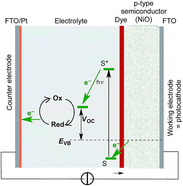
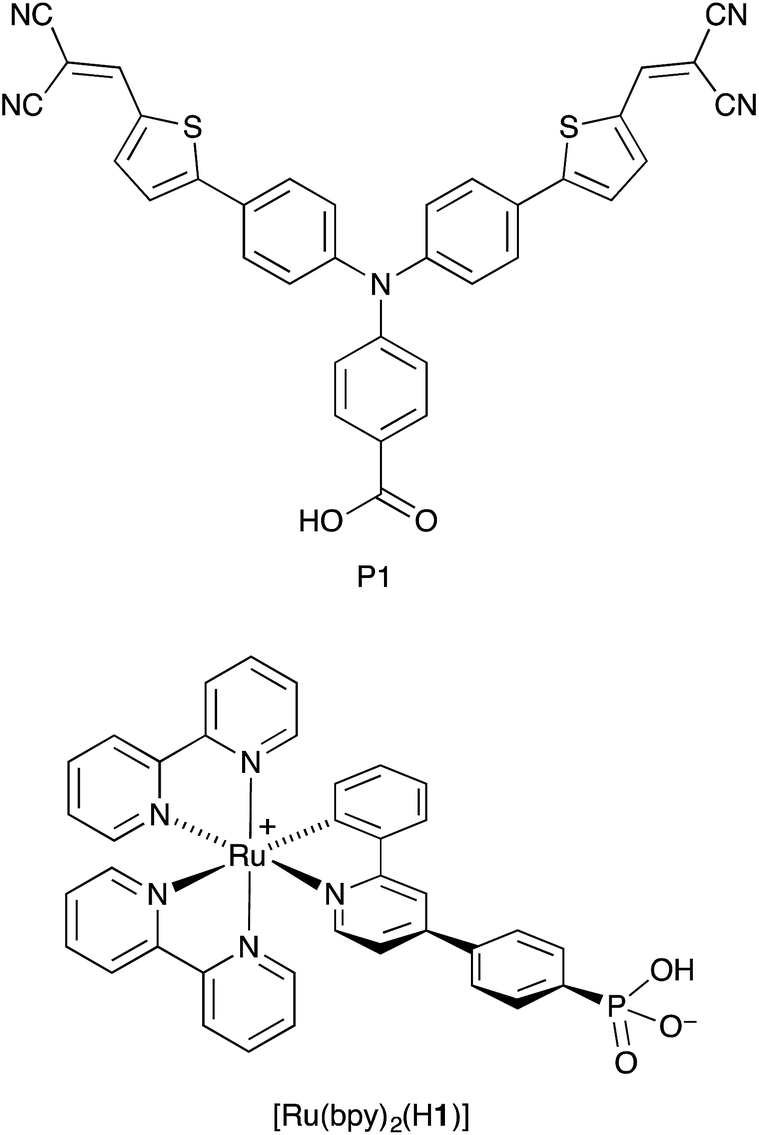
Cyclometallated ruthenium(II) complexes are appealing sensitizers for dye-sensitized solar cells (DSCs).1–3 The localization of the highest-occupied molecular orbital (HOMO) of a [Ru(N^N)2(C^N)]+ complex (N^N = bidentate N,N′-ligand, C^N = cyclometallated C,N-ligand) on the Ru/C^N domain4 permits tuning of the electronic properties of the complex through functionalization of the C,N-ligand. Unlike other classes of sensitizers such as organic dyes or metalloporphyrins, functional group variation of cyclometallated [Ru(N^N)2(C^N)]+ provides a flexible platform for use in both n- and p-type DSCs. In an n-type DSC, the C^N ligand plays an ancillary role (electron-pushing in a ‘push–pull’ dye architecture), whilst in a p-type DSC, the C^N domain bears the anchoring unit, typically a carboxylic or phosphonic acid.5–10 The optimization of [Ru(N^N)2(C^N)]+ dyes for p-type DSCs (the working principle of which is summarized in Fig. 1) is still in its infancy. Recently, we demonstrated that p-type DSCs with FTO/NiO photocathodes functionalized with the zwitterion [Ru(bpy)2(H1)] (Scheme 1) as sensitizer achieved short-circuit current densities (JSC) of up to 3.38 mA cm−2 and photoconversion efficiencies (η) of up to 0.116%. These values exceed those measured for the standard dye P1 (ref. 10 and 11) (Scheme 1). Despite the simple molecular architecture of [Ru(bpy)2(H1)], its photoconversion efficiency is comparable with that of the previously reported best-performing cyclometallated ruthenium(II) dye in p-type DSCs.5 Improvement of the performance of p-type DSCs is hindered by rapid recombination of reduced dye molecules and injected holes at the p-type semiconductor/dye interfaces, which militates against efficient dye regeneration at the dye/electrolyte interface.12 Hole transport resistance is typically high in p-type DSCs.
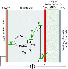 |
| | Fig. 1 A diagram showing the working principle of a p-type DSC. S and S* are the ground and excited states of the dye; EVB signifies the quasi-Fermi level of the valence band of the semiconductor; VOC = open circuit voltage. | |
 |
| | Scheme 1 Structures of sensitizers P1 and the zwitterion [Ru(bpy)2(H1)]. | |
In n-type DSCs, it is well established that the choice of solvent in the electrolyte plays a critical role in the device performance and stability.13,14 Ideally, the solvent should have a high boiling point to minimize cell degradation through solvent evaporation. Long-term stability of n-type DSCs has been demonstrated with tetraglyme-based I3−/I− electrolytes.15,16 Nonetheless, solvents such as acetonitrile, valeronitrile, propionitrile, butyronitrile, 3-methoxy propionitrile and propylene carbonate remain popular.17,18 Acetylacetone may also be a viable solvent in DSCs.19 Solvent polarity appears to play a key role, and it is noteworthy that DSC both JSC and in the open circuit voltage (VOC) by manipulation of the solvent polarity.20
In p-type DSCs, electrolytes have yet to be optimized. For our initial investigations of DSC performances with [Ru(bpy)2(H1)], we chose to use an I3−/I− based electrolyte in acetonitrile.10 This electrolyte composition has previously been used in liquid p-type DSCs with or without a TBP additive.21–26 The use of acetonitrile rather than propylene carbonate27 is known to enhance the short-circuit current density. We now report the effects on the performances of p-type DSCs sensitized by [Ru(bpy)2(H1)] of I3−/I− containing electrolytes in five different solvents. Initially, we assess the effects on JSC and VOC (and, hence, ultimately on η) of a change from acetonitrile (AN) to propionitrile (PN), valeronitrile (VN), 3-methoxypropionitrile (MPN) and N-methylpyrrolidone (NMP). Some relevant physical properties of these solvents are given in Table 1. Finally we consider the benefits of using mixed solvents.
Table 1 Selected properties of solvents used in this worka
| Solvent (abbreviation) |
Formula or structure |
Boiling point/°C |
Viscosity/mPa s |
Donor numberb |
|
Data from ref. 17 and 18; 1 cp = 1 mPa s.
Gutmann donor number, ref. 28.
|
| Acetonitrile (AN) |
CH3CN |
82 |
0.33 (at 30 °C) |
14.1 |
| Propionitrile (PN) |
CH3CH2CN |
97 |
0.39 (at 30 °C) |
16.1 |
| Valeronitrile (VN) |
CH3(CH2)3CN |
139 |
0.78 (at 19 °C) |
|
| 3-Methoxypropionitrile (MPN) |
CH3OCH2CH2CN |
164 |
2.5 (at 25 °C) |
16.1 |
|
N-Methylpyrrolidone (NMP) |

|
203 |
1.65 (at 25 °C) |
27.3 |
Experimental
Chemical reagents
All organic solvents were of HPLC high-purity grade. Acetonitrile (AN) was purchased from Macron™, EtOH from J.T. Baker®, propionitrile (PN), valeronitrile (VN), 3-methoxypropionitrile (MPN), N-methyl-2-pyrrolidone (NMP) from ACROS organics, LiI (99.9%), I2 (99.9%) from Sigma-Aldrich and [Ni(acac)2] from ACROS. The dye P1 was purchased from Dyenamo AB and [Ru(bpy)2(H1)] was prepared as previously described.10
NiO electrodes preparation
Working electrodes were either purchased from Dyenamo (DN-S01) or were prepared in-house. For the latter, an FTO glass plate was cleaned by sonicating in surfactant (2% in MilliQ water), and rinsed sequentially with MilliQ water and EtOH. The surface was activated in a UV-O3 system (Model 256-220, Jelight Company Inc) for 20 min. The glass was then immersed five times in a solution (AN 0.5 mM) of [Ni(acac)2] and air dried after each dipping. A layer of NiO paste (Ni-Nanoxide N/SP, Solaronix) was then screen-printed (90T, Serilith AG, Switzerland) onto the pretreated FTO plate. The plate was placed in an EtOH chamber for 3 min to reduce surface irregularities, then dried for 6 min at 125 °C on a heating plate. The screen printing process was repeated to give two layers. Both the commercial and in-house screen-printed electrodes were sintered by gradually heating from room temperature to 350 °C over a period of 30 min, kept at 350 °C for 30 min, then allowed to cool over ∼2 h to room temperature. After this sintering, the FTO/NiO plates were cut to make electrodes 1 cm × 2 cm. After the final sintering, the thickness of the in-house electrode NiO layer was typically 1.9–3.2 μm (by FIB measurements, recorded using a REM-FEI Helios Nano Lab 650). The Dyenamo NiO layer had a thickness of 2 μm (Dyenamo DN-S01).
DSC assembly
The working electrodes were heated at 250 °C for 20 min and then cooled to 80 °C before being immersed in an acetonitrile (AN) solution of P1 (0.3 mM) or EtOH solution of [Ru(bpy)2(H1)] (0.1 mM) for 20 h. The electrodes were removed from the solutions, washed with EtOH, then dried in an N2 stream. Commercial counter electrodes (Solaronix Test Cell Platinum Electrodes) were washed with EtOH and then heated at 450 °C (hot plate) for 30 min to remove volatile organic impurities.
The DSCs were assembled by combining working and counter electrodes using thermoplast hot-melt sealing foil (Solaronix, Meltonix 1170-25 Series, 60 μm thick) by heating while pressing them together. The electrolyte comprised I2 (0.1 M), LiI (1 M) in varying solvents (see text) and was introduced into the DSC by vacuum backfilling. The hole in the counter electrode was then sealed using a hot-melt sealing foil and cover glass.
Device performance measurements
The solar cell measurements were made using duplicate unmasked cells; the active area was 0.237 cm2 (in-house electrodes) or 0.25 cm2 (Dyenamo electrodes). The DSCs were sun-soaked from the anode side for 20 min at 1 sun irradiation. The cell was then inverted and measured immediately with a LOT Quantum Design LS0811 instrument (100 mW cm−2 = 1 sun at AM 1.5 and 23 °C) to obtain the current density–voltage (J–V) curves. The instrument software was set to a p-type measurement mode (inverted configuration), with a 360 ms settling time,10 and a voltage step of 5.3 mV. The voltage was scanned from negative to positive values.
Electrochemical impedance spectroscopy (EIS)
EIS measurements were carried out on a ModuLab® XM PhotoEchem photoelectrochemical measurement system from Solartron Analytical. The impedance was measured around the open-circuit potential of the cell at different light intensities (590 nm) in the frequency range 0.05 Hz to 400 kHz using an amplitude of 10 mV. The impedance data were analysed using ZView® software from Scribner Associates Inc.
Results and discussion
DSC working-electrodes: commercial versus screen-printed NiO electrodes
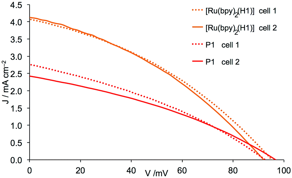
In previous investigations of p-type DCSs using in-house screen-printed FTO/NiO working electrodes sensitized with standard dye P1, optimal values of JSC, VOC and η (Table 2) were obtained using a [Ni(acac)2] pretreatment and two-layers of NiO.10 The results are consistent with the benchmarking study of Gibson and coworkers.11 The electrolyte in these investigations was I3−/I− in AN. We also demonstrated that the performance of the cyclometallated dye [Ru(bpy)2(H1)] exceeded that of P1.10 In the development of our p-type DSC program, we purchased commercial electrodes (Dyenamo) in order to compare the performance of DSCs sensitized with P1 or [Ru(bpy)2(H1)] with commercial and in-house screen-printed working electrodes. The commercial electrodes were sintered (see Experimental section) before being immersed for 20 h in an AN solution of P1 or EtOH solution of [Ru(bpy)2(H1)]. DSCs were assembled as described in the Experimental section using an I3−/I− redox couple in AN. Values of JSC, VOC, the fill-factor (ff) and η are given in Table 2, and the J–V curves for the DSCs with commercial electrodes are shown in Fig. 2. The fill-factors for all DSCs are in the range 32–36%. Compared to typical ff values of n-type DSCs, those for p-type cells are typically significantly lower,29 and the values in Table 2 compare well with the best reported for p-type DSCs. Both for the organic dye P1 and the cyclometallated ruthenium dye [Ru(bpy)2(H1)], a change from in-house screen-printed to commercial working electrodes results in an increase in the photoconversion efficiency. For P1, this originates from higher JSC and VOC, whereas for [Ru(bpy)2(H1)], only JSC is affected (Table 2). The values of JSC = 4.06 and 4.13 mA cm−2 for the ruthenium dye are notably higher than for previously reported cyclometallated ruthenium dyes5–8 and also higher than the 2.25 mA cm−2 reported for ruthenium diacetylide dyes.30 Values of JSC = 4.06 mA cm−2, VOC = 95 mV and η = 0.139% for the better performing cell of the duplicate pair in Table 2 set a new record for state-of-the-art5 cyclometallated ruthenium dyes in p-type DSCs. Furthermore, the values of JSC = 4.06 and 4.13 mA cm−2 obtained for the structurally unrefined [Ru(bpy)2(H1)] compare well with the 4.16 mA cm−2 obtained for the judiciously designed D–A–A organic dye (Scheme 2) reported recently by Zhu and coworkers in p-type DSCs;31 this dye was also used in conjunction with an I3−/I−/AN electrolyte. In order to understand the enhancement on going from P1 to [Ru(bpy)2(H1)], we turned to electrochemical impedance spectroscopy (EIS).
Table 2 Performance data for duplicate DSCs containing dyes [Ru(bpy)2(H1)] or P1. Measurements were made on the day of sealing the DSCs. Electrolyte = I3−/I− in MeCN
| Dye (DSC number) |
FTO/NiO electrodesb |
J
SC/mA cm−2 |
V
OC/mV |
ff/% |
η/% |
|
Data from ref. 10.
Fabricated in-house (see Experimental section) or commercial from Dyenamo.
|
| P1 (cell 1)a |
In-house |
1.84 |
88 |
35 |
0.057 |
| P1 (cell 2)a |
In-house |
1.96 |
82 |
32 |
0.051 |
| P1 (cell 1) |
Dyenamo |
2.76 |
92 |
33 |
0.085 |
| P1 (cell 2) |
Dyenamo |
2.42 |
97 |
34 |
0.079 |
| [Ru(bpy)2(H1)] (cell 1)a |
In-house |
3.38 |
95 |
36 |
0.116 |
| [Ru(bpy)2(H1)] (cell 2)a |
In-house |
3.34 |
95 |
34 |
0.109 |
| [Ru(bpy)2(H1)] (cell 1) |
Dyenamo |
4.06 |
95 |
36 |
0.139 |
| [Ru(bpy)2(H1)] (cell 2) |
Dyenamo |
4.13 |
92 |
36 |
0.136 |
 |
| | Fig. 2
J–V curves for duplicate DSCs containing commercial (Dyenamo) FTO/NiO electrodes functionalized with dyes P1 and [Ru(bpy)2(H1)] and an electrolyte comprising I3−/I− in MeCN. | |
 |
| | Scheme 2 The structure of the D–A–A organic dye with JSC = 4.16 mA cm−2 reported by Zhu and coworkers.31 | |
Electrochemical impedance spectroscopy: [Ru(bpy)2(H1)] versus P1
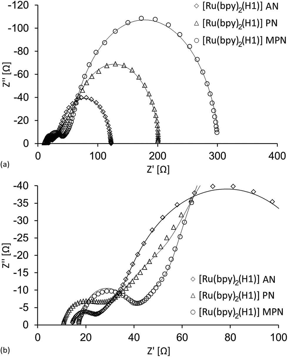
EIS is a diagnostic tool for investigating electrochemical processes in a system and has been extensively used to study the internal kinetics of n-type DSCs.32–34 An AC voltage of varying frequency is applied to the DSC and the resulting current response is measured. Measurements have most often been carried out on n-type DSCs, and the results are normally depicted as three semi-circles in the form of a Nyquist plot. In the high frequency region, the first impedance contains only the series resistance that primarily arises from the electrical resistance between the semiconducting particles and the FTO glass; other factors such as cable resistance also contribute. This resistance is presented in the plot on the abscissa from zero to the start of the first semi-circle starts. This semi-circle represents the impedance given by charge transfer at the surface of the cathode, normally a Pt/electrolyte interface. The second semi-circle (intermediate frequency region) stems from the charge transfer impedance of electron recombination reactions at the semiconductor/electrolyte interface. The third semi-circle, in the low frequency region, originates from the impedance of ion diffusion of the electrolyte. Depending on the magnitude of the recombination impedance and the ion diffusion impedance, this semi-circle may or may not be seen due to overlapping. It has been shown that the semi-circles obtained in EIS measurements of p-type DSCs originate from the same events as in n-type DSCs.35 Analysis of the EIS data allows multiple parameters including the recombination charge transfer resistance (Rrec), active layer surface chemical capacitance (Cμ), transport resistance (Rt) and cathode charge transfer resistance (RPt) to be extracted. In the EIS investigations described below and later in the paper, the DSCs were constructed using commercial (Dyenamo) FTO/NiO working electrodes.
In the first part of the EIS study, a comparison was made of DSCs containing the dyes P1 and [Ru(bpy)2(H1)] in combination with an I3−/I− electrolyte in AN. Although the observed values of VOC are similar for these two dyes (Table 2), JSC is significantly lower for P1, reaching only ∼60–70% of the values obtained for DSCs with [Ru(bpy)2(H1)] (Table 2 and Fig. 2). The EIS measurements reveal that DSCs with dye P1 exhibit a larger Rrec and Rt (Table 3 and Fig. 3) than those with the ruthenium dye. This would be the expected result if fewer charge carriers, (in this case holes) are injected into the NiO which is consistent with the lower JSC. Consequently, fewer holes are available for back reactions from the semiconductor into the electrolyte and Rrec increases. The lower Cμ found for DSCs containing P1 versus [Ru(bpy)2(H1)] (Table 3) further supports this assumption. A higher Rt implies a larger density of trapped charge carriers in the semiconductor and, in the case of the p-type cell, means that the valence band is at more positive potential and as a consequence there is a larger hole transport resistance. The similar VOC values for the two dyes (Table 2 and Fig. 2), together with the fact that the same redox couple is used in the electrolyte for all DSCs, indicates that the band gap in the NiO is independent of the dye used in this study. Normally, a higher Rrec is manifested in a higher VOC, but this is not observed in this case. Therefore, it is more reasonable to assume that, compared to sensitization by the ruthenium dye, it is the lower number of holes generated when P1 is used that is the origin of the higher Rrec and lower population of charge carriers.
Table 3 EIS data obtained from measurements at a light intensity of 22 mW cm−2 of p-type DSCs containing FTO/NiO (Dyenamo) working electrodes, dyes P1 or [Ru(bpy)2(H1)] and I3−/I− electrolyte in MeCN
| Dye |
R
t/Ω |
R
rec/Ω |
C
μ/μF |
R
Pt/Ω |
C
Pt/μF |
τ/ms |
| P1 (cell 1) |
55.9 |
159.1 |
1708.2 |
8.7 |
3.0 |
272 |
| P1 (cell 2) |
77.7 |
190.9 |
1240.0 |
7.4 |
4.5 |
237 |
| [Ru(bpy)2(H1)] (cell 1) |
39.6 |
87.9 |
2107.5 |
7.3 |
3.4 |
185 |
| [Ru(bpy)2(H1)] (cell 2) |
40.4 |
80.1 |
1883.4 |
7.1 |
3.7 |
151 |
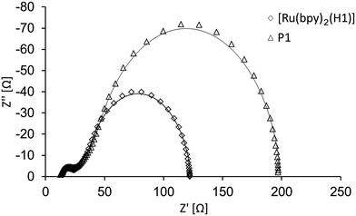 |
| | Fig. 3 Nyquist plots of two DSCs sensitized with [Ru(bpy)2(H1)] and P1 respectively; the electrolyte is I3−/I− in AN. Both Rrec and Rt are larger for P1 than the ruthenium dye. | |
Effects of electrolyte solvent on DSC performance
With the state-of-the-art performance of [Ru(bpy)2(H1)] as a sensitizer in p-type DSCs established, we initiated investigations of the effects of changing the electrolyte. Improvement of photoconversion efficiency and long-term device stability were both critical goals. For the present study, we retain the I3−/I− redox couple and focus on variation in the solvent. The low viscosity of AN (Table 1) contributes to its widespread use as a solvent, both for electrochemical studies and in DSCs.17 Although AN is commonly used in p-type DSCs (see the Introduction), its volatility is not compatible with long-term device stability. Increasing the length of the alkyl chain raises the boiling point, but also increases the viscosity (Table 1).
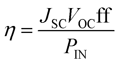
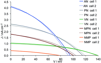
DSCs were assembled as described in the Experimental section using [Ru(bpy)2(H1)] as sensitizer and an electrolyte comprising I2 (0.1 M), LiI (1 M) in PN, VN, MPN or NMP. The working FTO/NiO electrodes were either commercial (Dyenamo) or were screen-printed using Solaronix NiO paste (see Experimental section). J–V measurements were made using duplicate cells and the performance data are given in Tables 4 and 5; the data are compared to those for DSCs using AN. Fig. 4 and 5 depict the J–V curves. For the discussion that follows, it is useful to recall the dependence of the overall DSC efficiency on JSC and VOC (eqn (1), in which PIN is the total solar power incident on the cell, 100 mW cm−2 for air mass 1.5).
| |  | (1) |
Table 4 Performance data for duplicate DSCs containing [Ru(bpy)2(H1)] and I3−/I− redox couple. Measurements were made on the day of sealing the DSCs. The FTO/NiO electrodes were purchased from Dyenamo
| Solvent in electrolytea |
DSC number |
J
SC/mA cm−2 |
V
OC/mV |
ff/% |
η/% |
|
Acetonitrile (AN); propionitrile (PN), valeronitrile (VN), 3-methoxypropionitrile (MPN); N-methylpyrrolidone (NMP).
Data from Table 2.
|
| ANb |
Cell 1 |
4.06 |
95 |
36 |
0.139 |
| ANb |
Cell 2 |
4.13 |
92 |
36 |
0.136 |
| PN |
Cell 1 |
2.63 |
115 |
39 |
0.117 |
| PN |
Cell 2 |
2.51 |
119 |
39 |
0.117 |
| VN |
Cell 1 |
1.04 |
139 |
42 |
0.060 |
| VN |
Cell 2 |
0.98 |
141 |
41 |
0.057 |
| MPN |
Cell 1 |
1.79 |
100 |
36 |
0.064 |
| MPN |
Cell 2 |
1.77 |
104 |
38 |
0.070 |
| NMP |
Cell 1 |
0.41 |
78 |
33 |
0.010 |
| NMP |
Cell 2 |
0.40 |
79 |
33 |
0.011 |
Table 5 Performance data for duplicate DSCs containing [Ru(bpy)2(H1)] and I3−/I− redox couple. Measurements were made on the day of sealing the DSCs. The FTO/NiO electrodes were purchased screen-printed using Solaronix NiO pastea
| Solvent in electrolyte |
DSC number |
J
SC/mA cm−2 |
V
OC/mV |
ff/% |
η/% |
|
Data from Table 1.
Data from ref. 10.
|
| ANb |
Cell 1 |
3.38 |
95 |
36 |
0.116 |
| ANb |
Cell 2 |
3.34 |
95 |
34 |
0.109 |
| PN |
Cell 1 |
2.18 |
115 |
40 |
0.099 |
| PN |
Cell 2 |
2.16 |
118 |
39 |
0.100 |
| VN |
Cell 1 |
0.64 |
149 |
36 |
0.033 |
| VN |
Cell 2 |
0.64 |
148 |
34 |
0.031 |
| MPN |
Cell 1 |
1.48 |
106 |
36 |
0.053 |
| MPN |
Cell 2 |
1.47 |
113 |
36 |
0.056 |
| NMP |
Cell 1 |
0.41 |
65 |
30 |
0.008 |
| NMP |
Cell 2 |
0.44 |
70 |
31 |
0.009 |
 |
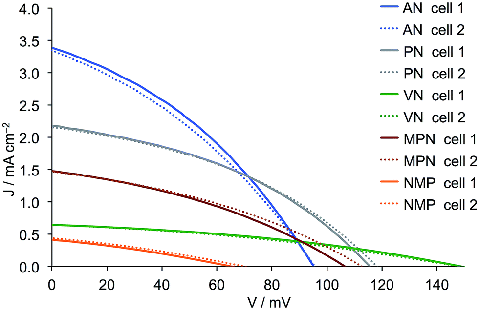
| | Fig. 4
J–V curves for duplicate DSCs containing commercial (Dyenamo) FTO/NiO electrodes functionalized with [Ru(bpy)2(H1)] and electrolytes comprising I3−/I− in different solvents. See footnote to Table 4 for solvent abbreviations. | |
 |
| | Fig. 5
J–V curves for duplicate DSCs containing FTO/NiO electrodes screen-printed using Solaronix NiO paste and functionalized with [Ru(bpy)2(H1)]. The electrolytes comprised I3−/I− in different solvents. See footnote to Table 4 for solvent abbreviations. | |
A comparison of the data in Tables 4 and 5 and of the J–V curves in Fig. 4 and 5 reveals the same trends irrespective of the source of the FTO/NiO electrodes. However, use of the commercial electrodes leads to higher values of JSC in all solvents except NMP. For AN, PN, VN and MPN, the fill-factors are in the range 34–42%. Values of JSC are solvent dependent in the order AN > PN > MPN > VN > NMP, whilst VOC follows the trend VN > PN > MPN > AN > NMP. With NMP, very low values of JSC and VOC both contribute to a poor overall η, and this solvent was therefore not further investigated. In the following discussion, we focus on the results obtained using commercial electrodes, noting that the trends are also valid for in-house screen-printed electrodes. Use of VN leads to impressive values of VOC (139 and 141 mV) but these are at the expense of JSC which, compared to the high values observed in AN, falls to around 1 mA cm−2, resulting in low overall photoconversion efficiencies of ∼0.06%. Although using AN leads to a VOC of only 92 or 95 mV, the remarkably good values of JSC > 4 mA cm−2 contribute to the best performing DSCs with η = 0.136 and 0.139%. A change from AN to the slightly less viscous PN results in a significant drop in JSC countered by a gain in VOC (Fig. 4). This is consistent with the increase in solvent donor number (Table 1).17 Overall, the DSCs retain a satisfactory overall efficiency of 0.117%.
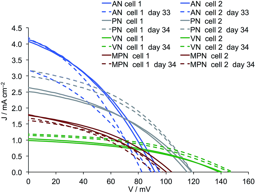
Although the results discussed above favour AN as the electrolyte solvent, the long-term stability of the DSCs remains an important factor. After the initial assessment of their performances, the DSCs were stored under ambient conditions for a month and then their J–V characteristics were remeasured (Table 6 and Fig. 6, S4†). The fill-factors of all DSCs remain relatively high. One DSC containing AN aged badly with a drop in both JSC and VOC, leading to a reduction in photoconversion efficiency from 0.139 to 0.088%. Pleasingly, the cells containing PN show enhanced performance upon ageing with a gain in JSC and no significant change in VOC. This leads to an increase in η from 0.117% to 0.154 and 0.146% for the two DSCs after 34 days, and this efficiency is essentially retained over the following 24 days. A ripening effect is also observed for the DSCs containing VN. Enhancement of DSC performance over time is a known phenomenon in n-type DSCs sensitized by some copper(I)36 or ruthenium(II) dyes and appears to be associated with the formation of dye-aggregates which ultimately reorganize on the surface over periods of days.37–39 DSCs containing MPN retain their original performances over the first 34 days and perform less well thereafter (Table 6).
Table 6 Long term performance data for duplicate DSCs containing [Ru(bpy)2(H1)] and I3−/I− redox couple. Commercial FTO/NiO electrodes (Dyenamo) were used
| Solvent in electrolyte |
DSC number |
J
SC/mA cm−2 |
V
OC/mV |
ff/% |
η/% |
| On day 33 or 34 (see Fig. 6) |
| AN |
Cell 1 |
3.17 |
89 |
34 |
0.096 |
| AN |
Cell 2 |
4.15 |
82 |
35 |
0.121 |
| PN |
Cell 1 |
3.17 |
119 |
41 |
0.154 |
| PN |
Cell 2 |
2.99 |
119 |
41 |
0.146 |
| VN |
Cell 1 |
1.18 |
148 |
44 |
0.077 |
| VN |
Cell 2 |
1.14 |
146 |
43 |
0.071 |
| MPN |
Cell 1 |
1.69 |
91 |
38 |
0.058 |
| MPN |
Cell 2 |
1.61 |
97 |
40 |
0.063 |
|
| On day 57 or 58 (see Fig. S4) |
| AN |
Cell 1 |
3.00 |
86 |
34 |
0.088 |
| AN |
Cell 2 |
3.81 |
83 |
32 |
0.102 |
| PN |
Cell 1 |
3.04 |
122 |
40 |
0.148 |
| PN |
Cell 2 |
2.96 |
118 |
41 |
0.142 |
| VN |
Cell 1 |
1.25 |
153 |
41 |
0.079 |
| VN |
Cell 2 |
1.06 |
155 |
39 |
0.065 |
| MPN |
Cell 1 |
1.37 |
89 |
29 |
0.035 |
| MPN |
Cell 2 |
1.38 |
101 |
31 |
0.043 |
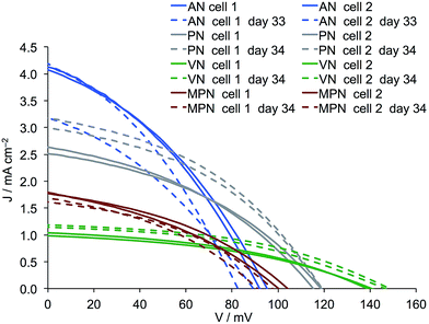 |
| | Fig. 6
J–V curves for duplicate DSCs containing commercial FTO/NiO electrodes functionalized with [Ru(bpy)2(H1)] and electrolytes comprising I3−/I− in AN, PN, VN or MPN. Measurements were made on day 0 and 33 or 34 days later. | |
Electrochemical impedance spectroscopy: solvent effects
As discussed above, the efficiencies of DSCs sensitized with [Ru(bpy)2(H1)] are significantly influenced by the choice of solvent in the electrolyte. The VOC is highest for VN and PN, but the main factor influencing the overall DSC efficiency is JSC. For the EIS study, DSCs using commercial FTO/NiO electrodes were used, and we focused only on the solvents AN, PN and MPN, all of which have similar donor numbers (Table 1). This effectively removes one variable and allows us observe more clearly the effects of the solvent viscosity which follows the order AN < PN < MPN which is the inverse of the trend in JSC (Fig. 4). A high viscosity decreases the diffusion coefficient for the redox mediators in the electrolyte40 and, following the reasoning discussed earlier, should lead to an increase in Rrec. The results of the EIS studies on duplicate cells (the same DSCs as used for the J–V measurements) are given in Table 7, and Nyquist plots for the better performing of each pairs of DSCs with commercial electrodes (see Table 4) are shown in Fig. 7.
Table 7 EIS data obtained from measurements at a light intensity of 22 mW cm−2 of p-type DSCs containing FTO/NiO (Dyenamo) working electrodes, the dye [Ru(bpy)2(H1)] and I3−/I− electrolyte in different solvents
| Solvent (DSC number) |
R
t/Ω |
R
rec/Ω |
C
μ/μF |
R
Pt/Ω |
C
Pt/μF |
τ/ms |
| AN (cell 1) |
39.6 |
87.9 |
2107.5 |
7.3 |
3.4 |
185 |
| AN (cell 2) |
40.4 |
80.1 |
1883.4 |
7.1 |
3.7 |
151 |
| PN (cell 1) |
96.4 |
146.3 |
1685.4 |
8.2 |
4.0 |
247 |
| PN (cell 2) |
109.0 |
129.3 |
1451.7 |
12.9 |
3.7 |
188 |
| MPN (cell 1) |
70.4 |
332.2 |
2170.3 |
20.4 |
4.0 |
721 |
| MPN (cell 2) |
56.6 |
248.6 |
2160.5 |
18.4 |
3.8 |
537 |
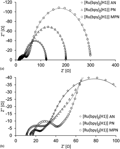 |
| | Fig. 7 (a) Nyquist plots of three cells sensitized with the dye [Ru(bpy)2(H1)] with different electrolyte solvents. (b) Expansion of the intermediate/high frequency region. | |
As the electrolyte viscosity increases, the ion diffusion decreases and the current density is lowered. This results in an increase in Rrec, since fewer charge carriers are available for back reaction. Both these changes can be observed in Tables 4 and 7. However, if Table 7 is studied, it can be seen that Cμ is highest for the MPN cells, meaning that the total density of charge carriers in the semiconductor is high.35 This, together with the highest Rrec results in a long charge carrier lifetime, or in other words, an efficient hole injection (Table 7). The hole transport resistance, Rt, is however lowest for the AN electrolyte while intermediate for the MPN electrolyte, and suggest that the cells with MPN have a higher density of charge carrier trap states. This agrees with the decreased JSC for the MPN cells. Furthermore, the high back electrode charge transfer resistance, RPt, is more than twice as large for the MPN cell compared to the AN one, and the performance deteriorates even further.
The PN cells possess the highest VOC, which is indicative of a larger band gap. Moreover, they have the largest values of Rt (Fig. 7b). Rt is directly affected by the valence band level, indicating that the latter is shifted towards a more positive potential for these cells. As mentioned above, a high Rt is suggestive of a high density of charge carrier trap states, and this together with the low chemical capacitance give rise to the relatively moderate performance of the PN cells.
Mixed solvents
In n-type DSCs, the use of mixed solvents is routine.17 These are commonly based on AN with a higher boiling organic nitrile, often VN or MPN, as cosolvent. Screening of AN, PN, VN and MPN for use with the I3−/I− redox couple and the dye [Ru(bpy)2(H1)] in p-type DSCs revealed benefits and disadvantages of each solvent. For optimal performance on the day the DSCs are made, AN is the superior solvent. PN or MPN lead to greater device stability, but at the expense of performance compared to AN. The highest values of VOC are obtained with VN.
A series of electrolytes was prepared using I2 (0.1 M), LiI (1 M) in mixed solvents as specified in Table 8. DSCs were assembled as described earlier and the device performances are summarized in Table 8 (Dyenamo FTO/NiO working electrodes) and Table S1† (in-house screen-printed electrodes). Fig. 8–10 and S1–S3† show the J–V curves. Use of duplicate DSCs, and a comparison of the data for the differently sourced working electrodes confirm the general trends discussed below. For the discussion, we focus only on the data in Table 8 and Fig. 8–10.
Table 8 Performance data for duplicate DSCs containing [Ru(bpy)2(H1)] and I3−/I− redox couple in mixed solvents, using commercial FTO/NiO electrodes (Dyenamo). Data for pure AN, PN, VN and MPN are repeated from Table 4 for convenience
| Solvent in electrolyte (ratio by volume) |
DSC number |
J
SC/mA cm−2 |
V
OC/mV |
ff/% |
η/% |
| AN |
Cell 1 |
4.06 |
95 |
36 |
0.139 |
| AN |
Cell 2 |
4.13 |
92 |
36 |
0.136 |
| AN:PN 3:1 |
Cell 1 |
3.64 |
99 |
38 |
0.138 |
| AN:PN 3:1 |
Cell 2 |
3.60 |
100 |
38 |
0.137 |
| AN:PN 1:1 |
Cell 1 |
3.34 |
115 |
37 |
0.142 |
| AN:PN 1:1 |
Cell 2 |
3.36 |
112 |
37 |
0.140 |
| AN:PN 1:3 |
Cell 1 |
2.79 |
106 |
38 |
0.111 |
| AN:PN 1:3 |
Cell 2 |
2.86 |
105 |
38 |
0.113 |
| PN |
Cell 1 |
2.63 |
115 |
39 |
0.117 |
| PN |
Cell 2 |
2.51 |
119 |
39 |
0.117 |
| AN:VN 3:1 |
Cell 1 |
3.14 |
115 |
39 |
0.141 |
| AN:VN 3:1 |
Cell 2 |
3.27 |
115 |
40 |
0.148 |
| AN:VN 1:1 |
Cell 1 |
2.43 |
119 |
40 |
0.115 |
| AN:VN 1:1 |
Cell 2 |
2.38 |
121 |
40 |
0.115 |
| AN:VN 1:3 |
Cell 1 |
1.58 |
133 |
42 |
0.087 |
| AN:VN 1:3 |
Cell 2 |
1.58 |
133 |
39 |
0.081 |
| VN |
Cell 1 |
1.04 |
139 |
42 |
0.060 |
| VN |
Cell 2 |
0.98 |
141 |
41 |
0.057 |
| AN:MPN 3:1 |
Cell 1 |
2.97 |
102 |
37 |
0.112 |
| AN:MPN 3:1 |
Cell 2 |
2.90 |
97 |
39 |
0.109 |
| AN:MPN 1:1 |
Cell 1 |
2.74 |
111 |
38 |
0.117 |
| AN:MPN 1:1 |
Cell 2 |
2.85 |
104 |
38 |
0.112 |
| AN:MPN 1:3 |
Cell 1 |
2.25 |
112 |
39 |
0.097 |
| AN:MPN 1:3 |
Cell 2 |
2.21 |
106 |
38 |
0.089 |
| MPN |
Cell 1 |
1.79 |
100 |
36 |
0.064 |
| MPN |
Cell 2 |
1.77 |
104 |
38 |
0.070 |
 |
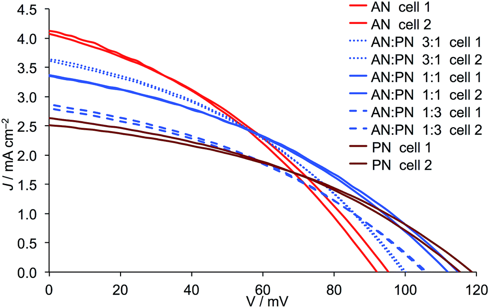
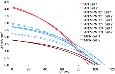
| | Fig. 8
J–V curves for duplicate DSCs containing Dyenamo FTO/NiO electrodes functionalized with [Ru(bpy)2(H1)] and electrolytes comprising I3−/I− in AN, PN or AN:PN mixed solvent. Ratios of solvents are by volume. | |
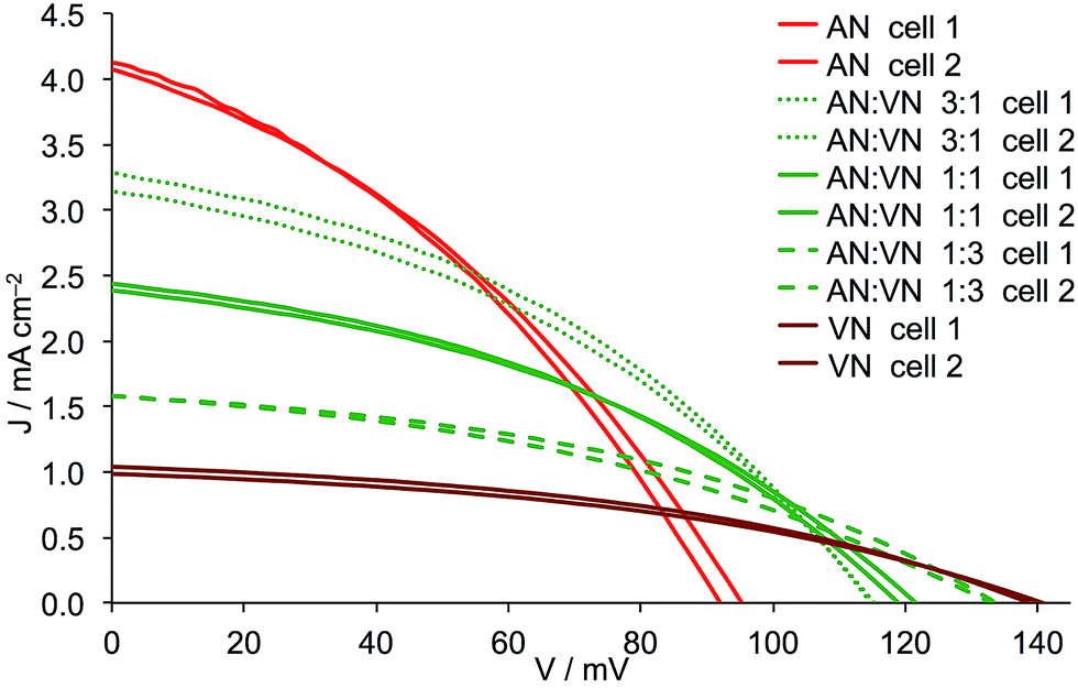
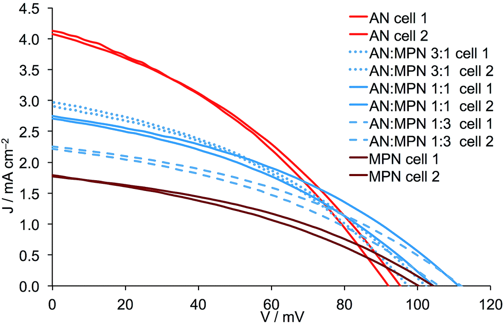
The addition of either PN, VN or MPN to AN leads to a reduction in JSC and this is most pronounced for VN and least for PN (Fig. 9versusFig. 8). Adding either PN or VN leads to an incremental increase in VOC as the amount of second solvent increases. These trends are consistent with the general observation (albeit it in n-type DSCs) that an increase in donor number (Table 1) results in lower JSC but improved VOC.17 Note that for AN/MPN, the optimal VOC is reached for 1:1 or 1:3 mixtures rather than for pure MPN (Fig. 10). For PN, the opposing trends in JSC and VOC along the solvent series from pure AN to a 3:1 and then to a 1:1 AN:PN mixture, led to little change in the overall DSC efficiency (Table 8). For both VN and MPN, the general trend is for a decrease in photoconversion efficiency as these solvents are mixed in increasing amounts with AN. Thus, the benefits of the higher VOC observed when solvents with a higher donor number are introduced into the electrolyte are only carried through to the overall efficiency when the second solvent is PN, the drop in JSC being too large in the cases of VN and MPN. The conclusion of this part of the investigation is that the optimal mixed solvent of those studied is an AN:PN mixture with volume ratios of 3:1 or 1:1 (Table 8).
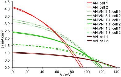 |
| | Fig. 9
J–V curves for duplicate DSCs containing Dyenamo FTO/NiO electrodes functionalized with [Ru(bpy)2(H1)] and electrolytes comprising I3−/I− in AN, VN or AN:VN mixed solvent. Ratios of solvents are by volume. | |
 |
| | Fig. 10
J–V curves for duplicate DSCs containing Dyenamo FTO/NiO electrodes functionalized with [Ru(bpy)2(H1)] and electrolytes comprising I3−/I− in AN, MPN or AN:MPN mixed solvent. Ratios of solvents are by volume. | |
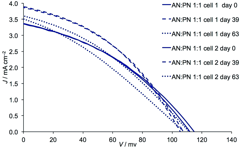
Finally, we consider the effects of ageing DSCs with the AN:PN mixtures. Table 9 gives the performance data for four cells in Table 8 in which the AN:PN volume ratios are 3:1 or 1:1. After 39 days, values of JSC increase while VOC remains stable (3:1 ratio) or falls (1:1 ratio) (Fig. 11). The fill-factors are little affected and the overall result is that η increases (Table 8versusTable 9) with the best photoconversion efficiency being 0.162%. The current densities of 3.86 and 3.89 mA cm−2 for these DSCs (Table 9) approach those recorded for DSCs on the day of cell fabrication in which the solvent is pure AN (Table 2). Further ageing results in a decrease in performance (Table 9 and Fig. 11) and a contributing factor is the lower fill-factors (31–38%), suggesting deterioration of the cell integrity. Nonetheless, the mixed solvent leads to noticeably better long-term stability than for the DSCs containing only AN (Table 9versusTable 6).
Table 9 Long term performance data for duplicate DSCs containing [Ru(bpy)2(H1)] and I3−/I− redox couple with AN, and AN:PN solvents. Commercial FTO/NiO electrodes (Dyenamo) were used
| Solvent in electrolyte |
DSC number |
J
SC/mA cm−2 |
V
OC/mV |
ff/% |
η/% |
| On day 39 |
| AN:PN 3:1 |
Cell 1 |
3.86 |
97 |
38 |
0.142 |
| AN:PN 3:1 |
Cell 2 |
3.88 |
100 |
41 |
0.158 |
| AN:PN 1:1 |
Cell 1 |
3.86 |
107 |
39 |
0.162 |
| AN:PN 1:1 |
Cell 2 |
3.89 |
105 |
40 |
0.162 |
|
| On day 63 |
| AN:PN 3:1 |
Cell 1 |
3.52 |
97 |
32 |
0.111 |
| AN:PN 3:1 |
Cell 2 |
3.62 |
99 |
38 |
0.138 |
| AN:PN 1:1 |
Cell 1 |
3.49 |
108 |
31 |
0.118 |
| AN:PN 1:1 |
Cell 2 |
3.59 |
111 |
35 |
0.139 |
 |
| | Fig. 11 Effects of ageing: J–V curves for duplicate DSCs containing Dyenamo FTO/NiO electrodes functionalized with [Ru(bpy)2(H1)] and electrolytes comprising I3−/I− in AN:PN mixed solvent 1:1 by volume. | |
Conclusions
We have investigated the effect of electrolyte solvent on the performances of p-type dye DSCs sensitized with the structurally simple cyclometallated ruthenium dye [Ru(bpy)2(H1)] adsorbed on FTO/NiO photocathodes and with an I3−/I− redox couple. Using AN as solvent in the electrolyte and with commercial FTO/NiO electrodes, values of JSC = 4.06 mA cm−2, VOC = 95 mV and η = 0.139% are achieved which are the highest reported for cyclometallated ruthenium dyes in p-type DSCs. JSC values for [Ru(bpy)2(H1)] are higher than those observed for the standard dye P1, and EIS shows that DSCs with [Ru(bpy)2(H1)] exhibit a both a lower transport resistance (Rt) and recombination resistance (Rrec) than DSCs with P1.
Screening of AN, PN, VN and MPN for use with the I3−/I− redox shuttle and sensitizer [Ru(bpy)2(H1)] leads to the conclusion that AN gives the highest JSC and highest η, but poorest long-term stability. DSCs with the less volatile and more viscous PN show a ripening effect over the first 33 days with a gain in JSC. Although exceptional values of VOC are obtained with VN, this is at the expense of JSC which decreases dramatically compared to values with AN as solvent. Values of JSC depend upon solvent in the order AN > PN > MPN > VN > NMP, whilst for VOC the trend is VN > PN > MPN > AN > NMP. As the electrolyte viscosity increases, the ion diffusion is reduced and, therefore, current density decreases. This is consistent with the EIS measurements which show an increase in Rrec due to fewer charge carriers being available for back reaction. However, it was also shown that the variation in Rrec does not completely account for the differences in DSC performance with solvent. The values of Rt and RP play a crucial role where Rt is highest for PN, whilst RPt is highest for the MPN cells.
Based upon the analysis of the benefits and disadvantages of the different solvents, electrolytes with mixed solvents were investigated. The addition of PN, VN or MPN to AN leads to lower JSC values, the change being most noticeable for VN and least so for PN. The optimal solvent is an AN:PN mixture with volume ratios of 3:1 or 1:1; this mixed solvent provides the DSCs with an enhanced long-term stability with respect to cells containing only AN and, significantly, this is achieved with only a small decrease in overall photoconversion efficiency.
Acknowledgements
We thank the Swiss National Science Foundation (Grant number CR22I2_156236) and the University of Basel for financial support. We thank (Cedric Wobill,10 Department of Chemistry, University of Basel) for providing [Ru(bpy)2(H1)]. Professor Ernst Meyer and Dr Thilo Glatzel (Department of Physics, University of Basel) for helpful discussions.
Notes and references
- K. C. D. Robson, P. G. Bomben and C. P. Berlinguette, Dalton Trans., 2012, 41, 7814 RSC and references therein.
- P. G. Bomben, K. C. D. Robson, B. D. Koivisto and C. P. Berlinguette, Coord. Chem. Rev., 2012, 256, 1438 CrossRef CAS and references therein.
- A. Colombo, C. Dragonetti, A. Valore, C. Coluccini, N. Manfredi and A. Abbotto, Polyhedron, 2014, 82, 50 CrossRef CAS and references therein.
- P. G. Bomben, K. C. D. Robson, P. A. Sedach and C. P. Berlinguette, Inorg. Chem., 2009, 48, 9631 CrossRef CAS PubMed.
- M. He, Z. Ji, Z. Huang and Y. Wu, J. Phys. Chem. C, 2014, 118, 16518 CAS.
- Z. Ji, G. Natu and Y. Wu, ACS Appl. Mater. Interfaces, 2013, 5, 8641 CAS.
- Z. Ji, G. Natu, Z. Huang, O. Kokhan, X. Zhang and Y. Wu, J. Phys. Chem. C, 2012, 116, 16854 CAS.
- Z. Ji and Y. Wu, J. Phys. Chem. C, 2013, 117, 18315 CAS.
- C. J. Wood, K. C. D. Robson, P. I. P. Elliott, C. P. Berlinguette and E. A. Gibson, RSC Adv., 2014, 4, 5782 RSC.
- F. Brunner, N. Marinakis, C. Wobill, M. Willgert, C. D. Ertl, T. Kosmalski, M. Neuburger, B. Bozic-Weber, T. Glatzel, E. C. Constable and C. E. Housecroft, J. Mater. Chem. C, 2016, 4, 9823 RSC.
- C. J. Wood, G. H. Summers, C. A. Clark, N. Kaeffer, M. Braeutigam, L. R. Carbone, L. D'Amario, K. Fan, Y. Farré, S. Narbey, F. Oswald, L. A. Stevens, C. D. J. Parmenter, M. W. Fay, A. La Torre, C. E. Snape, B. Dietzek, D. Dini, L. Hammarström, Y. Pellegrin, F. Odobel, L. Sun, V. Artero and E. A. Gibson, Phys. Chem. Chem. Phys., 2016, 18, 10727 RSC.
- M. Borgström, E. Blart, G. Boschloo, E. Mukhtar, A. Hagfeldt, L. Hammarström and F. Odobel, J. Phys. Chem. B, 2005, 109, 22928 CrossRef PubMed.
- T. Stergiopoulos, A. G. Kontos, V. Likodimos, D. Perganti and P. Falaras, J. Phys. Chem. C, 2011, 115, 10236 CAS.
- S. P. Mohanty and P. Bhargava, Electrochim. Acta, 2015, 168, 111 CrossRef CAS.
- T. Stergiopoulos, A. G. Kontos, N. Jiang, D. Milliken, H. Desilvestro, V. Likodimos and P. Falaras, Sol. Energy Mater. Sol. Cells, 2016, 144, 457 CrossRef CAS.
- A. G. Kontos, T. Stergiopoulos, V. Likodimos, D. Milliken, H. Desilvestro, G. Tulloch and P. Falaras, J. Phys. Chem. C, 2013, 117, 8636 CAS.
- Z. Yu, N. Vlachopoulos, M. Gorlov and L. Kloo, Dalton Trans., 2011, 40, 10289 RSC.
- J. Wu, Z. Lan, J. Lin, M. Huang, Y. Huang, L. Fan and G. Luo, Chem. Rev., 2015, 115, 2136 CrossRef CAS PubMed.
- V. Gondane and P. Bhargava, RSC Adv., 2016, 6, 37167 RSC.
- F. Hao, X. Jiao, J. Li and H. Lin, Nanoscale, 2013, 5, 726 RSC.
- L. Li, E. A. Gibson, P. Qin, G. Boschloo, M. Gorlov, A. Hagfeldt and L. Sun, Adv. Mater., 2010, 22, 1795 Search PubMed.
- P. Qin, M. Linder, T. Brinck, G. Boschloo, A. Hagfeldt and L. Sun, Adv. Mater., 2009, 21, 2993 CrossRef CAS.
- L. Zhu, H. Yang, C. Zhong and C. M. Li, Chem.–Asian J., 2012, 7, 2791 CrossRef CAS PubMed.
- P. Qin, J. Wiberg, E. A. Gibson, M. Linder, L. Li, T. Brinck, A. Hagfeldt, B. Albinsson and L. Sun, J. Phys. Chem. C, 2010, 114, 4738 CAS.
- Y.-S. Yen, W.-T. Chen, C.-Y. Hsu, H.-H. Chou, J. T. Lin and M. C. P. Yeh, Org. Lett., 2011, 13, 4930 CrossRef CAS PubMed.
- J. Cui, J. Lu, X. Xu, K. Cao, Z. Wang, G. Alemu, H. Yuang, Y. Shen, J. Xu, Y. Cheng and M. Wang, J. Phys. Chem. C, 2014, 118, 16433 CAS.
- P. Qin, H. Zhu, T. Edvinsson, G. Boschloo, A. Hagfeldt and L. Sun, J. Am. Chem. Soc., 2008, 130, 8570 CrossRef CAS PubMed.
- V. Gutmann, Coord. Chem. Rev., 1976, 18, 225 CrossRef CAS.
- Z. Huang, G. Natu, Z. Ji, M. He, M. Yu and Y. Wu, J. Phys. Chem. C, 2012, 116, 26239 CAS.
- S. Lyu, Y. Farré, L. Ducasse, Y. Pellegrin, T. Toupance, C. Olivier and F. Odobel, RSC Adv., 2016, 6, 19928 RSC.
- F. Wu, J. Liu, X. Li, Q. Song, M. Wang, C. Zhong and L. Zhu, Eur. J. Org. Chem., 2015, 6850 CrossRef CAS.
- F. Fabregat-Santiago, G. Garcia-Belmonte, I. Mora-Seró and J. Bisquert, Phys. Chem. Chem. Phys., 2011, 13, 9083 RSC.
- J. Bisquert, J. Electroanal. Chem., 2010, 646, 43 CrossRef CAS.
- F. Fabregat-Santiago, J. Bisquert, E. Palomares, L. Otero, D. Kuang, S. M. Zakeeruddin and M. Grätzel, J. Phys. Chem. C, 2007, 111, 6550 CAS.
- Z. Huang, G. Natu, Z. Ji, P. Hasin and Y. Wu, J. Phys. Chem. C, 2011, 115, 25109 CAS.
- C. E. Housecroft and E. C. Constable, Chem. Soc. Rev., 2015, 44, 8386 RSC and references therein.
- B. Wenger, M. Grätzel and J.-E. Moser, J. Am. Chem. Soc., 2005, 127, 12150 CrossRef CAS PubMed.
- B. Wenger, M. Grätzel and J.-E. Moser, Chimia, 2005, 59, 123 CrossRef CAS.
- V. K. Thorsmølle, B. Wenger, J. Teuscher, C. Bauer and J.-E. Moser, Chimia, 2007, 61, 631 CrossRef.
- T. Stergiopoulos, A. G. Kontos, V. Likodimos, D. Perganti and P. Falaras, J. Phys. Chem. C, 2011, 115, 10236 CAS.
Footnote |
| † Electronic supplementary information (ESI) available: Table S1. Additional DSC measurement data and J–V curves for mixed solvents. See DOI: 10.1039/c7se00060j |
|
| This journal is © The Royal Society of Chemistry 2017 |
Click here to see how this site uses Cookies. View our privacy policy here. 
 Open Access Article
 This Open Access Article is licensed under a Creative Commons Attribution-Non Commercial 3.0 Unported Licence
 ,
Edwin C.
Constable
and
Catherine E.
Housecroft
,
Edwin C.
Constable
and
Catherine E.
Housecroft