Rapid synthesis of self-supported three-dimensional bubble-like graphene frameworks as high-performance electrodes for supercapacitors†
Haiyan
Duan‡
,
Tingting
Yan‡
,
Zhenying
Li
,
Guorong
Chen
,
Jianping
Zhang
,
Liyi
Shi
and
Dengsong
Zhang
 *
*
Research Center of Nano Science and Technology, Shanghai University, Shanghai 200444, China. E-mail: dszhang@shu.edu.cn; Fax: +86 21 66136079
First published on 16th June 2017
Abstract
As one of the most desired alternatives for supercapacitor electrodes, three-dimensional graphene-based materials have attracted massive attention. However, they are still far from meeting the requirements for feasible and promising applications due to their low accessible surface area, poor electrical conductivity, unavailable interconnected self-supported frameworks, and complicated fabrication process. Herein, we originally and rapidly fabricated self-supported three-dimensional bubble-like graphene frameworks via the simpler and greener photopolymerization, which can be completed in a few seconds. The obtained graphene frameworks feature interconnected bubble networks composed of few-layered graphitic membranes, which are spatially and mutually supported. Besides, the simultaneously achieved huge available surface area, excellent conductivity, and superior wettability of the graphene frameworks can ensure sufficient active sites and promote efficient ion transportation, which can synergistically result in superior electrochemical performance when used as an electrode for supercapacitors. The resultant graphene-based supercapacitors exhibit a high gravimetric capacitance of 277 F g−1 at 1 A g−1, a remarkable rate-capability maintained at a level of 85% even at 50 A g−1 and superior cycling stability with 94% capacitance retention and ∼100% coulombic efficiency after 10![[thin space (1/6-em)]](https://www.rsc.org/images/entities/char_2009.gif) 000 cycles at 5 A g−1. A soft package symmetrical supercapacitor is also successfully assembled to power light-emitting diodes to demonstrate the promising application of the graphene frameworks. Therefore, the self-supported graphene bubble-networks overcome the defects of currently available graphene products and open avenues for fabricating high-performance, low-cost, high-quality graphene-based electrodes useful for supercapacitors.
000 cycles at 5 A g−1. A soft package symmetrical supercapacitor is also successfully assembled to power light-emitting diodes to demonstrate the promising application of the graphene frameworks. Therefore, the self-supported graphene bubble-networks overcome the defects of currently available graphene products and open avenues for fabricating high-performance, low-cost, high-quality graphene-based electrodes useful for supercapacitors.
1. Introduction
With energy and environment issues occurring more frequently, new energy-storage devices are urgently required to tackle this kind of threatening challenge. Supercapacitors have drawn tremendous attention as advanced energy storage devices that feature long cycle life, fast charge and discharge processes, high power density and excellent safety.1–3 Based on different mechanisms, electric double layer capacitors (EDLCs) and pseudocapacitors are included in supercapacitors. In EDLCs, the energy is electrostatically stored by a charge accumulation process at the active surface of an electrode.4,5 However, pseudocapacitors reserve energy through a reversible and rapid faradaic reaction.6 The EDLC mechanism is generally exhibited by carbon-based materials,7,8 and pseudocapacitance is always related to metal oxides and conductive polymers because of their rapid surface redox reactions.9–15 EDLC-based supercapacitors show greater potential than pseudocapacitors due to their exceptional characteristics, including higher power density, longer cycle stability, low cost and nontoxicity.8,16As is well-known, the performance of EDLC electrodes is closely related to the available surface area and the charge transmission dynamics. Therefore, a prerequisite for high specific capacitance is to achieve a high accessible surface area, suitable porous structures, high conductivity and superior wettability endowed by the electrode materials.17 Currently, carbon-based materials involving carbon aerogels, activated carbon, carbon nanotubes and graphene, have been extensively explored as superior electrodes for EDLC-based supercapacitors.18–23 Among these, graphene has attracted massive attention by virtue of its outstanding characteristics, such as large theoretical surface area (2600 m2 g−1), excellent conductivity and extraordinary electrochemical properties.24–29 Currently, chemically derived graphene sheets show great potential in the application of charge storage because of their high yielding and low-cost fabrication.30 However, the irreversible stacking of graphene sheets caused by π–π stacking interactions and van der Waals forces severely diminishes the accessible specific surface area and mass diffusion rate,31–35 thus resulting in a low capacitance. Furthermore, some guest materials including conductive polymers, metal hydroxides and metal oxides have been introduced as “spacers” into the graphene sheets to prevent restacking of graphene. The above graphene-based composites were successfully used as supercapacitor electrodes with enhanced specific capacitance.36–38 However, the incorporated materials experience gradual structural changes, including changes in the crystallinity and degree of hydration, during the process of reiterative reactions with ions, which is unfavorable to the cycle life. Therefore, new graphene structures are urgently required to achieve desirable sheet-to-sheet connectivity towards high performance in supercapacitors.
Three-dimensional (3D) graphene frameworks that engineer porous structures into graphene have recently attracted enormous attention, as the fabrication of porous graphene frameworks can effectively prevent the stacking of graphene sheets, which has been verified by us and other research groups.39–44 Additionally, the 3D graphene frameworks are promising because the interconnected graphene units can serve as more effective electron pathways and the massive pores enlarge the available surface area and facilitate ion diffusion, beneficial for the enhancement of the capacitive performance.45 In consideration of these intriguing features, certain efforts are currently being made in relation to the 3D graphene frameworks. Currently, 3D porous graphene networks are widely fabricated by chemical vapour deposition in the presence of templates such as metals,46 metal oxides47–49 and sulfides,50 sometimes along with additional catalysts to facilitate graphitization. However, these currently available 3D porous graphene frameworks are still far from meeting the requirements for feasible and promising applications due to their high production cost, and relatively time-consuming and energy-consuming fabrication methods. Thus, it is highly desirable to explore rapid methods for effectively fabricating 3D graphene frameworks for high-performance energy storage applications.
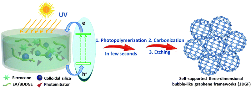
In this work, we originally and rapidly fabricate self-supported 3D bubble-like graphene frameworks (3DGFs) as high-performance electrodes for supercapacitors through photopolymerization and a subsequent ferrocene-incorporated calcination process. In our strategy, nanocomposite polymers can be obtained rapidly and efficiently under UV exposure in a few seconds at room temperature (the detailed reaction mechanism of photopolymerization is provided in the ESI†). Simultaneously, colloidal silica is utilized as a template to form abundant pores and ferrocene can be used to facilitate the catalytic graphitization of carbon. The simple fabrication process of the 3DGFs is illustrated in Scheme 1. Firstly, ferrocene was homogeneously mixed with a solution of epoxy acrylate resin (EA) and 1,4-butanediol diglycidyl ether (BDDGE), and then modified silica was adsorbed on the surface through a reaction between the active groups of EA/BDDGE and the modifier. Afterwards, nanocomposite polymers can be obtained efficiently via UV exposure in a few seconds at room temperature. Finally, after carbonization under flowing argon and further acid etching, self-supported 3D graphene bubble-networks were obtained. The obtained graphene frameworks feature bubble networks and high graphitic shells composed of few-layered graphene membranes, which are tightly fixed and spatially scaffolded by graphitic shells. In addition, a huge available surface area, excellent conductivity and superior wettability were simultaneously realized in these graphene frameworks, which can accelerate electron/ion transportation and eventually lead to excellent supercapacitive performance. In combination with the rapid and efficient preparation process, this strategy of photopolymerization may ensure possibilities for mass production of high-quality, low-cost, self-supported 3D porous graphene materials for next-generation supercapacitors.
2. Experimental section
Preparation
Epoxy acrylate resin (EA) was provided by Nanjing Fine Chemical Co. Ltd, and 1,4-butanediol diglycidyl ether (BDDGE) was purchased from TOKYO KASEI. Colloidal silica and triarylsulfonium hexafluoroantimonate salts (50 wt% in propylene carbonate) were purchased from Sigma-Aldrich. 3-(Trimethoxysilyl)propylmethacrylate (MPS) was provided by Aladdin. Tetraethylammonium tetrafluoroborate (TEABF4) and acetonitrile (ACN) were provided by Shanghai Auvic Technology Development Co., Ltd. Sinopharm Chemical Reagent Co. Ltd supplied the remaining materials.Briefly, 1.5 g of SiO2 was dialyzed in methanol solution and then modified with 0.62 g of MPS via ultrasonication to obtain modified silica. Then the modified silica was thoroughly mixed with 1.36 g of a mixture of EA and BDDGE, as well as 3.0 g of ferrocene to form a stable dispersion in an ultrasonic bath. Afterwards, 0.06 g of triarylsulfonium hexafluoroantimonate salts was added and the above solution was evaporated to obtain a condensed sol. The resultant sol was directly cured under UV radiation for a few seconds to produce solids. The above solids were carbonized under Ar atmosphere at 400 °C for 2 h, then at 1200 °C for 2 h. The SiO2 templates and metal species were removed by acid treatment to obtain 3DGFs.
For comparison, general carbon (GC) was prepared without the presence of SiO2 by calcinating under the same conditions.
Characterization
The microstructures of the obtained products were observed by field emission scanning electron microscopy (SEM, JEOL JEM-700F) and transmission electron microscopy (TEM, JEOL JEM-200 CX). High-Resolution TEM (HRTEM) images were obtained using a Tecnai G2 20 TWIN microscope operated at 200 kV. The power X-ray diffraction (XRD) tests were recorded on a Rigaku D/MAX-RB X-ray diffractometer (Cu Kα, 40 kV, 20 mA). The Raman spectra were acquired on a JY H800UV spectrometer equipped with an optical microscope. X-ray photoelectron spectroscopy (XPS) was performed on a PerkinElmer PHI 5000C ESCA system equipped with a dual X-ray source, using a 45 Mg Kα (1253.6 eV) anode and a hemispherical energy analyser. N2 adsorption–desorption measurements were conducted with an Autosorb-IQ2 (Quantachrome Corporation), and the samples were degassed at 593 K in a vacuum line before the tests. The specific surface areas and pore volumes were calculated by the Brunauer–Emmett–Teller method, and the quenched solid density functional theory was utilized to confirm the pore size distributions. The dynamic contact angle analysis of the electrodes was performed by employing a drop shape analysis system (Krüss, DSA100). A water drop of 1 μL with a rate of 1 μL s−1 was placed on the surface of the electrodes and series graphs were captured.Electrochemical measurements
| C = IΔt/mΔV | (1) |
![[thin space (1/6-em)]](https://www.rsc.org/images/entities/char_2009.gif) :
:![[thin space (1/6-em)]](https://www.rsc.org/images/entities/char_2009.gif) 1 and applying the mixture onto nickel foam. The electrodes were dried for 8 h at 120 °C and pressed for 30 s at 10 MPa. The mass of the electrode films was around 2 mg loaded in a 1 cm2 area. A sandwich-type capacitor composed of two similar material electrodes was assembled. The CV and CP tests for these devices were conducted in the potential range of 0–1 V. In the two-electrode set-up, the total gravimetric capacitance for the symmetric device (C) was calculated according to the equation:
1 and applying the mixture onto nickel foam. The electrodes were dried for 8 h at 120 °C and pressed for 30 s at 10 MPa. The mass of the electrode films was around 2 mg loaded in a 1 cm2 area. A sandwich-type capacitor composed of two similar material electrodes was assembled. The CV and CP tests for these devices were conducted in the potential range of 0–1 V. In the two-electrode set-up, the total gravimetric capacitance for the symmetric device (C) was calculated according to the equation:| C = IΔt/mΔV | (2) |
The energy density (E, W h kg−1) and power density (P, W kg−1) were calculated according to the following equations:
 | (3) |
| P = E/Δt | (4) |
3. Results and discussion
Characteristics
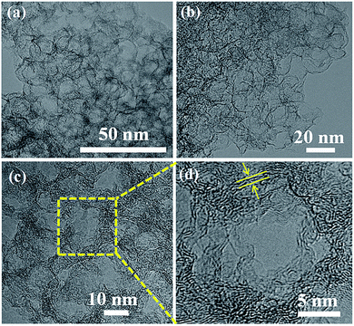
The TEM images in Fig. 1a illustrate that the as-formed 3DGF has a well-developed unique network featuring packed and interconnected bubbles, which is in good agreement with the original morphology of SiO2, and can also be clearly observed in the SEM images of the 3DGF (Fig. S1†). The skeletons of the bubbles and graphitic membranes are mutually supported to prevent the agglomeration of individual graphitic layers. Besides, no Fe species or SiO2 can be observed in the bubble networks, confirming the complete removal of Fe species and SiO2. As unambiguously confirmed by the TEM image presented in Fig. 1b, the resulting self-supported 3DGF presents 3D few-layer porous graphene structures with abundant channels, suggesting that the acid treatment did not destroy the interconnected networks. The above self-supported porous graphene structure is highly required for capacitive energy storage, simply because the 3D interconnected bubble frameworks can facilitate ion transfer and shorten the diffusion pathways. Further HRTEM examination in Fig. 1c clearly reveals reciprocally supported graphitic membranes with quite homogeneous thickness (ca. 1–2 nm). More detailed examination of the mesopore unit depicted in Fig. 1d indicates that the ultrathin carbon shells were composed of three to six graphene layers. Furthermore, it is noteworthy that the average diameter of the bubbles is 16 nm, which is highly consistent with the size of the colloidal silica templates (Fig. S2†). The self-supported interpenetrated graphene framework is robust and can function as a multidimensional conductive network to quickly transport electrons within the whole electrode matrix, which is significant to the rate performance of supercapacitors.However, the GC prepared without the presence of SiO2 exhibits severe aggregation instead of interconnected porous networks (Fig. S3†), which verifies the indispensable role of SiO2. Basically, the nanocomposite polymers can be obtained in a few seconds as a result of a photochemical process in which the chain transfer reactions are initiated. When the photoinitiator is activated by UV radiation energy, the generated active center will react with the unsaturated group and epoxy group, as well as interacting concurrently to form a cross-linked polymeric network. The nanocomposite polymers were subjected to microscopic characterization. The SEM images reveal that the nanocomposite polymers maintain a spherical structure (Fig. S4a†). The TEM images suggested that the above polymeric network structure is uniformly coated on the modified colloidal silica through a reaction between the active groups of the monomers and the modifier (Fig. S4b†). Notably, the self-supported 3DGF with an interconnected bubble architecture derived from the photo-induced nanocomposite polymers was rationally designed and innovatively prepared, representing a significant advancement in the fabrication of 3D graphene-based frameworks in terms of efficiency of the synthetic procedure as well as the quality of the resultant materials.
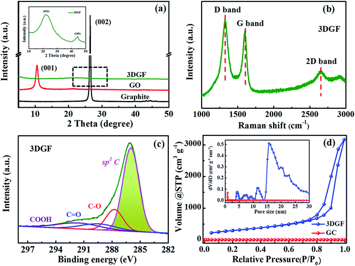
XRD measurements for the 3DGF, GO and graphite were conducted to probe the layer-to-layer spacing and exfoliation degree of the products (Fig. 2a). It can be obviously observed that only an intensive (001) peak at 10.3° is present in the XRD pattern of GO, revealing a larger interlayer spacing of GO compared with graphite due to the massive introduction of oxygen groups.51 For the 3DGF, the (001) peak at 10.3° vanishes and just a small embossment at 23.2° appears as observed from the inset of Fig. 2a, indicating that the intercalated oxygen-containing groups in the graphite interlayers are mostly removed and the conjugated structures are mostly recovered. Compared with the intense (002) peak of graphite, the broader and weaker (002) peak of the 3DGF indicates effective exfoliation and a higher crystallinity. This could be ascribed to the curvature and the ultrathin graphitic walls.52 In addition, no apparent diffraction peaks of impurities are detected, indicating the complete removal of the remaining SiO2 and Fe species from the carbon matrix, in good conformity with the TEM results. It can be concluded that the effectively exfoliated graphene layers of the 3DGF have been realized with the aid of a ferrocene-assisted calcination process. The intensity of the (002) peak of the 3DGF is also weaker than that of traditional graphene (TGR) (Fig. S5†), which further verifies the efficient exfoliation of few-layer graphene sheets in the 3DGF architectures. The resultant 3D few-layer graphene framework should be a desirable supercapacitor electrode due to the efficient ion transport channels provided by the interconnected self-supported frameworks of the 3DGF.
The structural and electronic characteristics of the 3DGF were further evaluated by Raman spectroscopy (Fig. 2b). The Raman spectrum of the 3DGF includes a D band centered at 1325 cm−1, a G band centered at 1600 cm−1, and a characteristic 2D band centered at 2650 cm−1. The highly graphitic nature of the membranes was confirmed by the prominent G and 2D bands.53,54 The intensity ratio of the 2D and G bands (I2D/IG) can be utilized to reflect the thickness of the graphene layers. A larger value always corresponds to a thinner layer of graphene. The I2D/IG of the 3DGF is calculated to be 0.60, suggesting the presence of few-layer graphene architectures.53,55,56 In addition, the strong disorder-induced D band reveals that the graphitization of the obtained 3DGF is inferior to that of few-layer graphene structures or ideal graphene constructed by CVD,53 though the graphitic degree of the 3DGF has been significantly enhanced. This strong band may be attributed to the structural imperfections introduced during the course of etching and/or carbonization. The few-layer graphitic structures ensure a higher conductivity as well as a smaller internal resistance,57 which is further verified in the following electrochemical measurements. In conclusion, SEM, TEM, HRTEM, XRD, and Raman spectroscopy confirmed that ferrocene-incorporated calcination effectively facilitated the formation of few-layer graphitic membranes without destroying the self-supported 3D porous structures.
In order to probe the oxygen-containing groups of the 3DGF, XPS tests were carried out. It should be noted that the O 1s peak intensities in the 3DGF spectrum are decreased noticeably compared to TGR, indicating that there are much fewer oxygen-containing functional groups in the 3DGF (5.73 at%) than in TGR (14.9 at%) (Fig. S6†). The measured spectra strongly proved the prominent decrease in oxygen-containing groups in 3DGF, which was further probed in Fig. 2c. The C 1s spectrum of the 3DGF contains four main peaks centered at 286.0, 287.8, 289.6 and 291.8 eV, which can be ascribed to the sp2 aromatic rings, C–O, C![[double bond, length as m-dash]](https://www.rsc.org/images/entities/char_e001.gif) O and COOH, respectively. The well-retained conjugated structure after thermal treatment was strongly verified by the strong peak for sp2 carbon. Thus, it is demonstrated that the 3DGF with high deoxygenating ability has interconnected conjugated graphene bubble-frameworks, which can facilitate charge storage and transfer in a supercapacitor.
O and COOH, respectively. The well-retained conjugated structure after thermal treatment was strongly verified by the strong peak for sp2 carbon. Thus, it is demonstrated that the 3DGF with high deoxygenating ability has interconnected conjugated graphene bubble-frameworks, which can facilitate charge storage and transfer in a supercapacitor.
Furthermore, N2 adsorption–desorption measurements were carried out to explore the porous structure and specific surface area of the 3DGF. As depicted in Fig. 2d, a typical type-IV isotherm is vividly exhibited for the 3DGF, and the large hysteresis loop is at a relatively higher pressure ranging from 0.7 to 1.0. This evident hysteresis loop reveals the presence of uniform mesopores,58–60 which is due to the removal of the colloidal silica templates through the acid treatment process.
The specific surface area and pore volume of the 3DGF are calculated to be as high as 1183 m2 g−1 and 5.0 cm3 g−1, which are significantly higher than those of GC (21 m2 g−1 and 0.03 cm3 g−1). The larger specific surface area further shows strong evidence for the effective prevention of irreversible agglomeration of the graphene layers due to the self-supported 3D porous architectures when using SiO2 as a template. The pore size distribution profiles of the 3DGF in the inset of Fig. 2d successfully verified the enormous pores of around 16 nm formed between the self-supported 3D foam-like graphene frameworks. The pores of ∼16 nm agree well with the size of colloidal silica. Therefore, it can be concluded that the 3DGF fabricated through the UV-induced polymerization method effectively avoids the stacking of graphene sheets, remarkably increasing the accessible specific surface area. The substantial pores serve as ion transportation pathways and ensure abundant active sites. In addition, the 3D interconnected graphene units can function as more efficient electron channels and facilitate the mass diffusion rate. These improved physical properties of the 3DGF are generally conducive to the supercapacitive performance.
In addition to the above unique structural characteristics, the wettability of the 3DGF is also quite attractive. Fig. 3 vividly shows the dynamic contact angle measurements for water droplets on each electrode. Interestingly, the 3DGF is quite hydrophilic due to the original contact angle of 36° and the entirely absorbed droplet within 6 s. For comparison, the dynamic contact angle measurements of GC are also presented. It should be noted that the contact angle of GC decreased rather slowly as time went on, suggesting that it was highly hydrophobic. When the contact time reaches 6 s, the contact angle of GC is only down to 109°. Besides, the 3DGF also presents better wettability than TGR (Fig. S7†). In conclusion, the 3DGF possessed greatly improved wettability due to the homogeneous 3D porous networks. The superior wettability of the 3DGF is anticipated to enhance the ion available surface area and accelerate ion transportation, thus resulting in better supercapacitor performance.
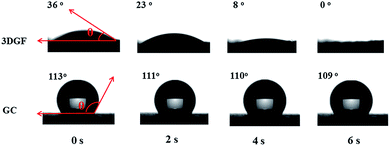 | ||
| Fig. 3 Optical micrographs of the water contact angles on the surface of 3DGF and GC electrodes as a function of contact time. | ||
Electrochemical performance
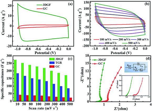
The electrochemical properties of the 3DGF and GC were first assessed in a 6 M KOH electrolyte with a three-electrode system. Nearly symmetrical rectangular-like shapes of the CV curves at 50 mV s−1 for the 3DGF and GC were apparently observed in Fig. 4a, indicating typical electrical double layer behaviors. Furthermore, the rectangular-like shape of the CV curve for the 3DGF is significantly better than that of TGR (Fig. S8†) and GC. Fig. 4b displays the CV curves of the 3DGF capacitor ranging from 100 mV s−1 to 500 mV s−1. The CV curves retained good rectangular-like shapes and reversible electrochemical behavior, even when increased to 500 mV s−1, indicating its superior rate performance. It has been verified that the rectangular-like degree of the CV curve is closely associated with the charge transfer and ion diffusion rate in the porous networks of the 3DGF electrode. Additionally, the 3DGF presents a much larger enclosed area of the loop than GC and TGR at any scan rate (Fig. S9†), indicating an intensive gravimetric capacitance.61 It was visually observable in Fig. 4c that the gravimetric capacitance of the 3DGF capacitors was always larger than that of GC and TGR at any scan rate (10–500 mV s−1), and these results apparently elucidate the better supercapacitive behavior and rate capability of the 3DGF. Obviously, the self-supported porous structures, highly graphitic shells composed of three-six graphene layers, good wettability and superior electrical conductivity will potentially facilitate the faster movement and accumulation of ions across the self-supported 3D graphene conductive networks.EIS analysis was performed to examine the ion transmission property of the electrolyte ions within the 3DGF and GC capacitors in a 6.0 M KOH electrolyte. As depicted in Fig. 4d, the Nyquist profiles all consisted of vertical lines in the low frequency region and small quasi-semicircles in the high frequency one.62 The Nyquist plot is fitted and elaborated through the equivalent electric circuit (the inset of Fig. 4d). The relatively straight line in the low-frequency range confirms the dominating contribution of ion electrosorption. The high frequency range is in parallel with the limiting process of charge transfer and can be ascribed to the double layer capacitance (Cdl). The width of the quasi-semicircles plotted corresponds to the charge transfer resistance (Rct). The real axis intercept in the Nyquist plots is the equivalent series resistance (RESR), and a smaller RESR value generally indicates lower internal resistance and a faster charge/discharge rate.63 The inclined line, resulting from the Warburg impedance (ZW), corresponds to the ion-diffusion process. It should be noted that the Rct of the 3DGF is negligible, revealing the ultra-small Rct compared to TGR. Furthermore, as can be seen from the inset, the RESR value of the 3DGF is 0.54 Ω, smaller than that of GC (0.85 Ω), indicating that the bubble-like networks of the 3DGF can facilitate charge transfer and the diffusion of ions, beneficial for its application in supercapacitors. The large ZW observed for the GC capacitor verifies the slower ion transport due to the inadequate ion channels in the GC.
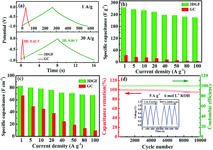
Fig. 5a presents the CP curves of the 3DGF and GC capacitors at different current densities of 1 A g−1 and 30 A g−1. It can be vividly observed that the CP plots of the 3DGF and GC capacitors both display nearly symmetrical triangular shapes, indicating typical electric double layer behavior and superior electrochemical reversibility.56,57 Significantly, almost linear potential-time plots even at 30 A g−1 are observed, suggesting the fast current–voltage response in the adsorption process. Besides, the sudden voltage drop (IR drop) during the initial discharge stage can be used to reveal the inner resistance of the capacitor. As can be seen, the 3DGF presents a rather smaller voltage (IR) drop of 0.06 V than GC (0.42 V), which is highly consistent with the smaller RESR as determined from the EIS evaluation. In addition, the 3DGF capacitor was calculated to achieve a capacitance of 277 F g−1 at 1 A g−1 and even 235 F g−1 when increasing to 50 A g−1 for the 3DGF capacitor (Fig. 5b and S10†), confirming an excellent rate performance of 85% retention, much higher than recently reported carbon products with comparable testing conditions (Table S1†). However, the GC capacitor only presents a gravimetric capacitance of 35 F g−1 at 1 A g−1, significantly lower than that of the 3DGF capacitor. A close comparison also shows that the 3DGF always led to a higher gravimetric capacitance than GC at any current density. Additionally, the 3DGF capacitor presents higher gravimetric capacitance than recently reported carbon materials with comparable test conditions (Table S2†).
Besides, the volumetric performance can be utilized to reveal how much and how fast energy can be stored in a unit volume of material.64 However, an equilibrium relationship generally exists between the packing density and the porosity of materials. A well-developed porous electrode can ensure a high accessible surface area and accelerate the transmission and diffusion of ions, which can contribute to the significantly enhanced gravimetric capacitance, but a decreased volumetric capacitance because of its relatively low packing density. A highly compact electrode can increase the volumetric capacitance but reduce the available surface area and transmission rate of ions, which can lead to a low gravimetric capacitance and poor rate capability.65 The packing density of the 3DGF is 0.30 g cm−3 because of its interconnected bubble-like networks, which is significantly lower than that of GC (1.40 g cm−3). But the volumetric capacitance of the 3DGF is still much higher than that of GC at any current density, e.g., 83.1 versus 67.2 F cm−3 at 1 A g−1. The above observation clearly confirms that the obtained 3DGF shows significantly improved electrochemical performance as a supercapacitor electrode. This can be ascribed to the following features: (i) high accessible surface area to guarantee abundant active sites for charge storage; (ii) high conductivity, which facilitates ion transportation and diffusion; (iii) good wettability to promote ion diffusion and enlarge the ion-available surface area and (iv) a shortened ion transmission distance in the 3D nanometer dimension and modulated, stable self-supported porous structures to enhance the gravimetric capacitance and rate capability.
The long-term cycling abilities of capacitors is a paramount factor for their practical applications in supercapacitors. Therefore, the cyclic capability of the 3DGF capacitor was evaluated at 5 A g−1 (Fig. 5d). It was noted that the 3DGF presented superior cycle ability with 94% gravimetric capacitance retention with a coulombic efficiency of ∼100% when cycling 10![[thin space (1/6-em)]](https://www.rsc.org/images/entities/char_2009.gif) 000 times. The nearly identical CP curves during the first and last three cycles also indicate the high cycling stability (inset in Fig. 5d). The above results clearly validate that the 3DGF possesses superior electrochemical stability in the three-electrode configuration.
000 times. The nearly identical CP curves during the first and last three cycles also indicate the high cycling stability (inset in Fig. 5d). The above results clearly validate that the 3DGF possesses superior electrochemical stability in the three-electrode configuration.
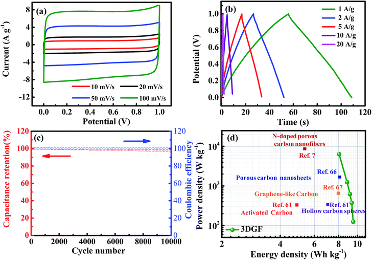
In order to simulate the practical device behavior of the 3DGF, a symmetrical sandwich-type two-electrode system with the same 3DGF material on both electrodes was fabricated. As presented in Fig. 6a, all the CV curves of the 3DGF show rectangular-like shapes, suggesting a rapid dynamic process and reversible electrochemical behavior. Similarly, the CP curves of the 3DGF in Fig. 6b all show nearly symmetrical triangular shapes. The above measurements both reveal a superior electric double layer capacitive behavior. The 3DGF sandwich-type capacitor achieved a high gravimetric capacitance of 50.2 F g−1 at 1 A g−1. When increased to 10 A g−1, the 3DGF capacitor retained a high gravimetric capacitance of 38.2 F g−1 with a retention rate of 76.1%, confirming the excellent rate capability when the 3DGF is used in a three-electrode testing system. Furthermore, the cyclic capability and coulombic efficiency of the 3DGF capacitor were evaluated at 3 A g−1 (Fig. 6c). It can be calculated that the 3DGF presented superior cycle ability with 96% gravimetric capacitance retention and ∼100% coulombic efficiency after 10![[thin space (1/6-em)]](https://www.rsc.org/images/entities/char_2009.gif) 000 cycles. The Ragone plots depicted in Fig. 6d further demonstrate the superior performance of the 3DGF capacitor. The energy density of the 3DGF reaches 9.51 W h kg−1, which is significantly better than that of previously reported carbon-based supercapacitors in aqueous electrolytes.7,61,66,67 The significantly improved performance of the 3DGF is mainly ascribed to the unique bubble-like graphene frameworks, which combine the superiority of huge available specific surface area, self-supported interconnected porous structures, high conductivity and outstanding wettability. The synergistic effect of these features ensures more accessible surface area and enrichment of active sites for fast ion accumulation and transport, thus resulting in a high gravimetric capacitance, superior rate capability, and outstanding cycling ability.
000 cycles. The Ragone plots depicted in Fig. 6d further demonstrate the superior performance of the 3DGF capacitor. The energy density of the 3DGF reaches 9.51 W h kg−1, which is significantly better than that of previously reported carbon-based supercapacitors in aqueous electrolytes.7,61,66,67 The significantly improved performance of the 3DGF is mainly ascribed to the unique bubble-like graphene frameworks, which combine the superiority of huge available specific surface area, self-supported interconnected porous structures, high conductivity and outstanding wettability. The synergistic effect of these features ensures more accessible surface area and enrichment of active sites for fast ion accumulation and transport, thus resulting in a high gravimetric capacitance, superior rate capability, and outstanding cycling ability.
To demonstrate the promising application of the self-supported 3D bubble-like graphene frameworks, a soft package symmetrical supercapacitor was successfully assembled using an electrolyte of 1 M TEABF4/ACN (the working voltage is lower than 2.7 V). Impressively, the 3DGF symmetrical supercapacitor can power a light-emitting diode (2.03 V, 20 mA) with continuous lighting after charging to 2.1 V within 3 minutes (Fig. 7). These results further indicate that the rapidly fabricated 3DGF materials possess superior supercapacitor behavior.
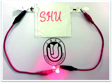 | ||
| Fig. 7 Schematic illustration of the soft package 3DGF supercapacitor and a photograph showing the lighting of an LED. | ||
4. Conclusions
In summary, we have successfully prepared cost-effective, self-supported porous 3DGF electrodes using a green and facile method of photopolymerization, and demonstrated their excellent supercapacitive performance. By taking advantage of tightly connected graphitic membranes and mutually supported graphitic shells, high conductivity, high accessible surface area and superior wettability, the obtained supercapacitors presented excellent electrochemical performance with a high gravimetric capacitance of 277 F g−1 at 1 A g−1, superior rate-capability maintained at a level of 85% when the current density ranged from 1 A g−1 to 50 A g−1, and excellent cycle stability with 94% retention and ∼100% coulombic efficiency when cycling 10![[thin space (1/6-em)]](https://www.rsc.org/images/entities/char_2009.gif) 000 times at 5 A g−1. A soft package supercapacitor is also successfully assembled to drive light-emitting diodes to demonstrate the practicability of our 3DGF. Therefore, this work demonstrated opportunities for large-scale fabrication of high-performance self-supported 3D porous graphene for supercapacitors with large gravimetric capacitance, remarkable rate-capability and superior cycling stability.
000 times at 5 A g−1. A soft package supercapacitor is also successfully assembled to drive light-emitting diodes to demonstrate the practicability of our 3DGF. Therefore, this work demonstrated opportunities for large-scale fabrication of high-performance self-supported 3D porous graphene for supercapacitors with large gravimetric capacitance, remarkable rate-capability and superior cycling stability.
Acknowledgements
The authors gratefully acknowledge the State Key Research and Development Plan (2017YFB0102200), Science and Technology Commission of Shanghai Municipality (16JC1401700 and 16DZ1204300).Notes and references
- P. Simon, Y. Gogotsi and B. Dunn, Science, 2014, 343, 1210–1211 CrossRef CAS PubMed.
- B. C. Kim, J.-Y. Hong, G. G. Wallace and H. S. Park, Adv. Energy Mater., 2015, 5, 1500959–1500991 CrossRef.
- S. Yang, R. E. Bachman, X. Feng and K. Müllen, Acc. Chem. Res., 2013, 46, 116–128 CrossRef CAS PubMed.
- G. Wang, L. Zhang and J. Zhang, Chem. Soc. Rev., 2012, 41, 797–828 RSC.
- H. Wang, L. Zhi, K. Liu, L. Dang, Z. Liu, Z. Lei, C. Yu and J. Qiu, Adv. Funct. Mater., 2015, 25, 5420–5427 CrossRef CAS.
- B. G. Choi, M. H. Yang, S. C. Jung, K. G. Lee, J.-G. Kim, H. S. Park, T. J. Park, S. B. Lee, Y.-K. Han and Y. S. Huh, ACS Nano, 2013, 7, 2453–2460 CrossRef CAS PubMed.
- L. F. Chen, X. D. Zhang, H. W. Liang, M. G. Kong, Q. F. Guan, P. Chen, Z. Y. Wu and S. H. Yu, ACS Nano, 2012, 6, 7092–7102 CrossRef CAS PubMed.
- L. L. Zhang and X. S. Zhao, Chem. Soc. Rev., 2009, 38, 2520–2531 RSC.
- L. Wang, X. Feng, L. Ren, Q. Piao, J. Zhong, Y. Wang, H. Li, Y. Chen and B. Wang, J. Am. Chem. Soc., 2015, 137, 4920–4923 CrossRef CAS PubMed.
- A. Gutierrez-Pardo, B. Lacroix, J. Martinez-Fernandez and J. Ramirez-Rico, ACS Appl. Mater. Interfaces, 2016, 8, 30890–30898 CAS.
- X. Cao, C. Tan, X. Zhang, W. Zhao and H. Zhang, Adv. Mater., 2016, 28, 6167–6196 CrossRef CAS PubMed.
- F. Cao, M. Zhao, Y. Yu, B. Chen, Y. Huang, J. Yang, X. Cao, Q. Lu, X. Zhang, Z. Zhang, C. Tan and H. Zhang, J. Am. Chem. Soc., 2016, 138, 6924–6927 CrossRef CAS PubMed.
- J. Zhou, J. Song, H. Li, X. Feng, Z. Huang, S. Chen, Y. Ma, L. Wang and X. Yan, New J. Chem., 2015, 39, 8780–8786 RSC.
- X. Feng, J. Zhou, L. Wang, Y. Li, Z. Huang, S. Chen, Y. Ma, L. Wang and X. Yan, New J. Chem., 2015, 39, 4026–4034 RSC.
- Y. Guo, W. Li, H. Yu, D. F. Perepichka and H. Meng, Adv. Energy Mater., 2016, 7, 1601623 CrossRef.
- J. Liu, L. Zhang, H. B. Wu, J. Lin, Z. Shen and X. W. Lou, Energy Environ. Sci., 2014, 7, 3709–3719 CAS.
- C. Liu, Z. Yu, D. Neff, A. Zhamu and B. Z. Jang, Nano Lett., 2010, 10, 4863–4868 CrossRef CAS PubMed.
- X. Yang, C. Cheng, Y. Wang, L. Qiu and D. Li, Science, 2013, 341, 534 CrossRef CAS PubMed.
- A. Izadi-Najafabadi, S. Yasuda, K. Kobashi, T. Yamada, D. N. Futaba, H. Hatori, M. Yumura, S. Iijima and K. Hata, Adv. Mater., 2010, 22, E235–E241 CrossRef CAS PubMed.
- D. N. Futaba, K. Hata, T. Yamada, T. Hiraoka, Y. Hayamizu, Y. Kakudate, O. Tanaike, H. Hatori, M. Yumura and S. Iijima, Nat. Mater., 2006, 5, 987–994 CrossRef CAS PubMed.
- J. S. Jilei Liu and L. Gao, J. Phys. Chem. C, 2010, 114, 19614–19620 Search PubMed.
- Q. Wang, J. Yan, Z. Dong, L. Qu and Z. Fan, Energy Storage Mater., 2015, 1, 42–50 CrossRef.
- S. A. B. N. Levy, K. L. Meaker, M. Panlasigui, A. Zettl, F. Guinea and M. F. C. A. H. Castro Neto, Science, 2010, 329, 544–547 CrossRef PubMed.
- A. K. Geim, Science, 2009, 324, 1530–1534 CrossRef CAS PubMed.
- A. K. Geim and K. S. Novoselov, Nat. Mater., 2007, 6, 183–191 CrossRef CAS PubMed.
- S. Stankovich, D. A. Dikin, G. H. Dommett, K. M. Kohlhaas, E. J. Zimney, E. A. Stach, R. D. Piner, S. T. Nguyen and R. S. Ruoff, Nature, 2006, 442, 282–286 CrossRef CAS PubMed.
- X. Yang, C. Cheng, Y. Wang, L. Qiu and D. Li, Science, 2013, 341, 534–537 CrossRef CAS PubMed.
- M. F. El-Kady, V. Strong, S. Dubin and R. B. Kaner, Science, 2012, 335, 1326–1330 CrossRef CAS PubMed.
- C. N. Rao, A. K. Sood, K. S. Subrahmanyam and A. Govindaraj, Angew. Chem., Int. Ed., 2009, 48, 7752–7777 CrossRef CAS PubMed.
- M. Segal, Nat. Nanotechnol., 2009, 4, 612 CrossRef CAS PubMed.
- Y. Sun, Q. Wu and G. Shi, Energy Environ. Sci., 2011, 4, 1113–1132 CAS.
- Y. Xu, Z. Lin, X. Zhong, X. Huang, N. O. Weiss, Y. Huang and X. Duan, Nat. Commun., 2014, 5, 4554–4561 CAS.
- Y. Zhu, S. Murali, W. Cai, X. Li, J. W. Suk, J. R. Potts and R. S. Ruoff, Adv. Mater., 2010, 22, 3906–3924 CrossRef CAS PubMed.
- Z. Wen, X. Wang, S. Mao, Z. Bo, H. Kim, S. Cui, G. Lu, X. Feng and J. Chen, Adv. Mater., 2012, 24, 5610–5616 CrossRef CAS PubMed.
- J. Luo, H. D. Jang, T. Sun, L. Xiao, Z. He, A. P. Katsoulidis, M. G. Kanatzidis, J. M. Gibson and J. Huang, ACS Nano, 2011, 5, 8943–8949 CrossRef CAS PubMed.
- X. C. Dong, H. Xu, X. W. Wang, Y. X. Huang, M. B. Chanpark, H. Zhang, L. H. Wang, W. Huang and P. Chen, ACS Nano, 2012, 6, 3206–3213 CrossRef CAS PubMed.
- J. Yan, Z. Fan, T. Wei, W. Qian, M. Zhang and F. Wei, Carbon, 2010, 48, 3825–3833 CrossRef CAS.
- X. Feng, N. Chen, J. Zhou, Y. Li, Z. Huang, L. Zhang, Y. Ma, L. Wang and X. Yan, New J. Chem., 2015, 39, 2261–2268 RSC.
- Y. Li, Z. Li and P. K. Shen, Adv. Mater., 2013, 25, 2474–2480 CrossRef CAS PubMed.
- D. Zhou, Y. Cui, P. W. Xiao, M. Y. Jiang and B. H. Han, Nat. Commun., 2014, 5, 4716–4722 CrossRef CAS PubMed.
- H. Duan, T. Yan, G. Chen, J. Zhang, L. Shi and D. Zhang, Chem. Commun., 2017 10.1039/c7cc03424e.
- J. Hao, Y. Liao, Y. Zhong, D. Shu, C. He, S. Guo, Y. Huang, J. Zhong and L. Hu, Carbon, 2015, 94, 879–887 CrossRef CAS.
- L. Sheng, Y. Liang, L. Jiang, Q. Wang, T. Wei, L. Qu and Z. Fan, Adv. Funct. Mater., 2015, 25, 6545–6551 CrossRef CAS.
- B. G. Choi, M. Yang, W. H. Hong, J. W. Choi and Y. S. Huh, ACS Nano, 2012, 6, 4020 CrossRef CAS PubMed.
- X. Wang, Y. Zhang, C. Zhi, X. Wang, D. Tang, Y. Xu, Q. Weng, X. Jiang, M. Mitome, D. Golberg and Y. Bando, Nat. Commun., 2013, 4, 2905–2912 Search PubMed.
- Z. Chen, W. Ren, L. Gao, B. Liu, S. Pei and H. M. Cheng, Nat. Mater., 2011, 10, 424 CrossRef CAS PubMed.
- H. Nishihara and T. Kyotani, Adv. Mater., 2012, 24, 4473–4498 CrossRef CAS PubMed.
- M. Q. Zhao, Nat. Commun., 2014, 5, 3410–3417 Search PubMed.
- C. Cui, W. Qian, Y. Yu, C. Kong, B. Yu, L. Xiang and F. Wei, J. Am. Chem. Soc., 2014, 136, 2256–2259 CrossRef CAS PubMed.
- H. J. Peng, J. Liang, L. Zhu, J. Q. Huang, X. B. Cheng, X. Guo, W. Ding, W. Zhu and Q. Zhang, ACS Nano, 2014, 8, 11280–11289 CrossRef CAS PubMed.
- H. Wang, D. Zhang, T. Yan, X. Wen, J. Zhang, L. Shi and Q. Zhong, J. Mater. Chem. A, 2013, 1, 11778–11789 CAS.
- M. A. Worsley, T. T. Pham, A. Yan, S. J. Shin, J. R. Lee, M. Baggehansen, W. Mickelson and A. Zettl, ACS Nano, 2014, 8, 11013–11022 CrossRef CAS PubMed.
- C. Wang, Y. Wang, J. Graser, R. Zhao, F. Gao and M. J. O'Connell, ACS Nano, 2013, 7, 11156–11165 CrossRef CAS PubMed.
- X. Li, M. Chi, S. M. Mahurin, R. Liu, Y.-J. Chuang, S. Dai and Z. Pan, Carbon, 2016, 101, 57–61 CrossRef CAS.
- D. Graf, F. Molitor, K. Ensslin, C. Stampfer, A. Jungen, C. Hierold and L. Wirtz, Nano Lett., 2007, 7, 238–242 CrossRef CAS PubMed.
- D. Graf, F. Molitor, K. Ensslin, C. Stampfer, A. Jungen, C. Hierold and L. Wirtz, Nano Lett., 2007, 7, 238–242 CrossRef CAS PubMed.
- X. Lou, P. Wu, A. Zhang, R. Zhang and Y. Tang, ACS Appl. Mater. Interfaces, 2015, 7, 20061–20067 CAS.
- R. Liu, Y. Shi, Y. Wan, Y. Meng, F. Zhang, D. Gu, Z. Chen, B. Tu and D. Zhao, J. Am. Chem. Soc., 2006, 128, 11652–11662 CrossRef CAS PubMed.
- G. Wang, Y. Sun, D. Li, H. W. Liang, R. Dong, X. Feng and K. Mullen, Angew. Chem., 2015, 127, 15406–15411 CrossRef.
- W. Wei, H. Liang, K. Parvez, X. Zhuang, X. Feng and K. Mullen, Angew. Chem., Int. Ed., 2014, 53, 1570–1574 CrossRef CAS PubMed.
- F. Xu, Z. Tang, S. Huang, L. Chen, Y. Liang, W. Mai, H. Zhong, R. Fu and D. Wu, Nat. Commun., 2015, 6, 7221–7230 CrossRef PubMed.
- H. Li, J. Song, L. Wang, X. Feng, R. Liu, W. Zeng, Z. Huang, Y. Ma and L. Wang, Nanoscale, 2017, 9, 193–200 RSC.
- S. Zhang and N. Pan, Adv. Energy Mater., 2015, 5, 1401401–1401420 CrossRef.
- Y. G. A. P. Simon, Science, 2011, 334, 917–918 CrossRef PubMed.
- Q. Wang, J. Yan and Z. Fan, Energy Environ. Sci., 2016, 9, 729–762 CAS.
- X. Fan, C. Yu, J. Yang, Z. Ling, C. Hu, M. Zhang and J. Qiu, Adv. Energy Mater., 2015, 5, 1401761–1401767 CrossRef.
- J. Zhao, Y. Jiang, H. Fan, M. Liu, O. Zhuo, X. Wang, Q. Wu, L. Yang, Y. Ma and Z. Hu, Adv. Mater., 2017, 29, 1604569–1604575 CrossRef PubMed.
Footnotes |
| † Electronic supplementary information (ESI) available: Experimental section; the reaction mechanism of photopolymerization; SEM images of 3DGF; TEM images and the corresponding particle size distribution histograms of colloidal silica; TEM images of GC; SEM images and TEM images of nanocomposite polymers; XRD patterns of TGR; XPS spectra of the 3DGF and the TGR (survey scan); optical micrographs of the water contact angles on the surface of TGR as a function of contact time; CV curves of TGR; CV curves of the GC and TGR capacitors at various scan rates; CP curves of the 3DGF capacitors at various current densities; comparison of the rate performance of carbon-based electrodes from the literature; comparison of the capacitance and detailed information on the mass loading of various carbon electrode materials from the literature. See DOI: 10.1039/c7se00178a |
| ‡ These authors contributed equally to this work. |
| This journal is © The Royal Society of Chemistry 2017 |

