Vapor-fed solar hydrogen production exceeding 15% efficiency using earth abundant catalysts and anion exchange membrane†
Gino
Heremans
 a,
Christos
Trompoukis
ab,
Nick
Daems
 a,
Tom
Bosserez
a,
Ivo F. J.
Vankelecom
a,
Johan A.
Martens
a and
Jan
Rongé
a,
Tom
Bosserez
a,
Ivo F. J.
Vankelecom
a,
Johan A.
Martens
a and
Jan
Rongé
 *a
*a
aCentre for Surface Chemistry and Catalysis, KU Leuven, Celestijnenlaan 200F, B-3001 Heverlee, Belgium. E-mail: jan.ronge@kuleuven.be
bDepartment of Information Technology, Photonics Research Group, Ghent University, Technologiepark Zwijnaarde 15, B-9000 Ghent, Belgium
First published on 25th September 2017
Abstract
Vapor-fed solar hydrogen generators can convert water vapor from the air into hydrogen using sunlight as the energy source. Hydrogen and oxygen evolution reactions are performed in the gas phase in cathode and anode compartments separated by a membrane. Anion exchange membranes show great promise for this type of solar hydrogen generator. They provide an alkaline environment enabling the use of earth abundant materials as electrocatalysts. In this work, a vapor-fed solar hydrogen generator with KOH-doped poly(vinyl alcohol) anion exchange membrane flanked with NiFe and NiMo catalysts is demonstrated. The device reached an average 15.1% solar-to-hydrogen efficiency at room temperature and 95% relative humidity. This first demonstration of gas phase water splitting with earth abundant catalysts and anion exchange membrane opens a pathway to low cost, autonomous, efficient and safe solar hydrogen generators.
Solar-driven water electrolysis is a strategy to produce renewable hydrogen gas that can be used as transportation fuel, for seasonal energy storage or for industrial application.1 Large scale solar hydrogen production is still limited by its high price compared to hydrogen produced from fossil hydrocarbons.2 Electrolytic hydrogen production currently is driven by grid electricity, which increasingly originates from renewable power sources. Efficiency could be gained and cost reduced by integrating the functions of electric power generation and water electrolysis in a single device, as is the case in a solar hydrogen generator.3 Solutions incorporating photovoltaic junctions have been most successful.3–7 In particular, electrically coupled but spatially separated photovoltaic-electrolysis devices routinely achieve good stability and solar-to-hydrogen (STH) efficiencies exceeding 10%.8–14 In order to prevent high costs due to the low utilization rate of the electrolysis components, the use of low cost materials or current concentration, by reducing the electrolysis area relative to the light absorber, is imperative.2,15,16 Proton exchange membrane (PEM) water electrolysis employs noble metal catalysts and operates at high current densities.17 PEMs have low gas permeation which enables a compact design with fast dynamic response, a broad operational range and high current loads.18 However, until now no earth-abundant oxygen evolution catalyst has been discovered that is stable at low pH and can be integrated in a PEM electrolysis cell.
To retain the benefits of a PEM while avoiding the use of noble metals, an alkaline anion exchange membrane (AEM) can be implemented. AEMs have been introduced in water electrolyzers only recently.18–21 In comparison with a PEM, AEMs pose two drawbacks: moderate ionic conductivity and limited stability of the AEM.22 Both obstacles are circumvented in an integrated solar-driven water electrolysis device. Under direct illumination, lower current densities are generated (ca. 10 mA cm−2) which results in low ohmic losses in the electrolysis device. Previous demonstrations of solar-driven alkaline water electrolysis incorporating an anion exchange membrane made use of concentrated aqueous KOH electrolyte causing membrane degradation.1,9,23,24 Membrane stability could be enhanced by avoiding concentrated solutions and working under gas phase conditions instead.25,26 Gas phase and air-based water splitting was recently proposed and experimentally demonstrated.27–34 The water vapor content of air is sufficient to supply a solar hydrogen generator with water molecules even by natural convection.27,30 The use of outside air closes the water cycle, minimizes contamination of the membrane and resolves a number of engineering challenges.28,30,31 Overall, using outside air for solar hydrogen production could lead to low cost, autonomous and safe solid-state devices. Kumari et al. have demonstrated gas phase water electrolysis using a PEM and noble metal catalysts. In conjunction with a triple junction a-Si solar cell, a STH efficiency of 6.3% was reported. In this work, a vapor-fed solar hydrogen generator with AEM and earth abundant catalysts is demonstrated for the first time.
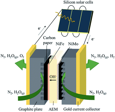
The membrane electrode assembly consisted of a KOH-doped poly(vinyl alcohol) (PVA) AEM sandwiched between NiFe and NiMo catalysts electrodeposited on carbon paper (Fig. 1). Electric contact was made via gold current collectors and graphite plates with serpentine channels which allow gas flow over the catalyst surface. The active area of the electrolysis device was fixed at 4 cm2. Three commercial c-Si solar cells were connected in series, with a total active area of 3.54 cm2 (module area of 4.62 cm2), and electrically coupled with the electrolysis device.
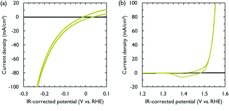
NiFe and NiMo are among the most active non-noble metal catalysts for respectively the oxygen and hydrogen evolution reactions under alkaline conditions.35–38 Both catalysts were electrodeposited on carbon paper, which functioned as electrically conducting support and gas diffusion layer. The electrodeposition conditions were adopted from literature (Table S1†).39,40 After deposition, cyclic voltammetry was performed to measure the activity of the catalysts in 1 M KOH. The polarization curves, obtained at a scan rate of 10 mV s−1, are shown in Fig. 2. The catalytic activity was similar to that reported in literature.39,40 In order to achieve a current density of 10 mA cm−2, the required overpotentials for the hydrogen and oxygen evolution reactions were 74 and 275 mV, respectively. The carbon paper used to support the catalysts was inert in the selected voltage range (Fig. 2).
KOH-impregnated PVA was used as solid electrolyte to provide hydroxide conductivity and to separate the produced gases. PVA is a low cost material that has superior chemical stability and high hydrophilicity,41 which are desirable characteristics for gas phase water splitting. The PVA membranes were made by solution casting.42 Before assembly of the electrolysis device, each membrane was doped with 4 M KOH, which is reported to generate the highest conductivities and increased plasticity.43
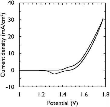
Fig. 3 shows the current–voltage characteristic of the assembled electrolysis device fed with water vapor at 95% relative humidity (RH). Only 1.63 V was required to generate a current density of 10 mA cm−2. This is in close agreement with the required potential for the catalysts to achieve the same current density in 1 M KOH (1.58 V) (Fig. 2). The additional overpotential required in the electrolysis device can largely be explained by ohmic losses, estimated by electrochemical impedance spectroscopy to be 32 mV, which was mainly caused by the electric wires to make contact. At low scan rates, a saturation current density of ca. 23 mA cm−2 becomes apparent from the voltammograms (Fig. S2†) and is attributed to mass transfer limitations of water vapor.32
Minimizing gas diffusion through the membrane is critical to prevent back reaction at the electrodes and to achieve hydrogen gas with high purity.22 Therefore, the outlet gas streams of the anode and cathode compartments were characterized and quantified over time with a mass spectrometer during electrolysis (Fig. S3†). Faradaic efficiencies of near 100% were recorded for both anode and cathode gas outlets, suggesting that hydrogen gas with high purity is produced at the cathode compartment and no degradation of carbon paper is occurring. This was confirmed by cross-over measurements (Fig. S4†) and by measuring carbon dioxide at the anode compartment, which was not detected. These results demonstrate that for devices operating at low current densities, a membrane with sufficient thickness can be chosen to avoid cross-over, while retaining low ohmic losses.
At reduced RH (85%), a decrease in performance was observed (Fig. S5†). A current density of 10 mA cm−2 was achieved at a potential of 1.69 V. After regeneration with humidified nitrogen gas (95% RH), the electrolysis device recovered its initial performance. Since the overall resistance of the electrolysis device was almost the same for both RH (Fig. S6†), the decline in performance at reduced RH could not be explained by the lower equilibrium hydration levels of the membrane. Various studies have shown that the catalyst layer is of prime importance to retain high activity at lower RH.25,26 The catalyst layer should be sufficiently thick to maintain high ionic conductivity and catalytic surface area, but should also be sufficiently thin in order to prevent gas diffusion limitations. It was noticed that the redox wave ascribed to nickel reduction (NiOOH → Ni(OH)2)44 at 1.36 V became smaller at 85% RH. The integrated wave area is in direct correlation with the active surface area of the NiFe catalyst that is available to perform water oxidation.44 Thus, loss of active catalyst surface area as observed at 85% RH is a possible reason for the decrease in performance. In this work, an ionomer coating was absent and the catalytic electrodes were simply pressed into the soft KOH-doped PVA membrane. We note that this method does not adversely affect device performance at high RH (Fig. 3). However, optimization of the catalyst layer is needed to obtain better performance at reduced RH.
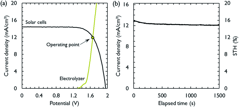
The most suitable operating voltage and current density for the integrated solar hydrogen generator can be determined by overlaying the current–voltage characteristic of the vapor-fed electrolysis device with the characteristic of the photovoltaic.32,45 Appropriate matching consists of finding a photovoltaic which provides the highest possible photocurrent while still supplying sufficient photovoltage to drive the electrolysis device at the desired current density. Here, three commercial c-Si solar cells (IXYS KXOB22-12X1F) were connected in series to provide the driving force for the electrochemical reactions in the electrolysis device. The current–voltage characteristic of the triple-cell solar module was recorded with a Xe lamp equipped with IR and AM 1.5 filters calibrated at 1 sun intensity (Fig. 4a). Under these conditions, the solar module achieved an open circuit potential (Voc) of 1.96 V, a short circuit current density (Jsc) of 14.46 mA cm−2 and a power conversion efficiency of 20.57% at its maximum power point (Vmpp = 1.54 V, Jmpp = 13.36 mA cm−2). As aforementioned, the operating point of the solar hydrogen generator is predicted by the intersection of both characteristics. The electrolysis device was operated with nitrogen gas at 95% RH and at room temperature. Using polarization curves obtained at 1 mV s−1 the operating point is found at a current density of 12.2 mA cm−2 and a potential of 1.66 V. At a faradaic efficiency of 100% (Fig. S4†), the STH efficiency can be defined as the product of the power conversion efficiency, the electrolysis efficiency and the coupling efficiency:
| STH = ηSTH = ηPCEηelηc = 15.0% | (1) |
 | (2) |
 | (3) |
 | (4) |
The very close matching of the solar module and the electrolysis device near the maximum power point results in a coupling loss of less than 2%. Since the potential at the operating point is slightly above the maximum power point, a small increase in the operating voltage of the electrolysis device could potentially result in a significant loss of STH effiency.9 However, when the solar module was directly connected with the electrolysis device, a relatively stable performance was observed (Fig. 4b). An initial STH efficiency of 15.8% was obtained which declined and stabilized at 14.8% over the course of 1500 seconds. The average STH efficiency during the experiment was 15.1%. The decrease could be caused by an increasing operating voltage of the electrolysis device (Fig. S7†) and a reduced photovoltage due to heating of the solar module. We note that only the solar module was illuminated. In a real-life solar hydrogen generator, the electrolysis device is expected to heat up as well, leading to a performance gain.46,47 In a longer experiment, the device showed a small performance loss during 8 h of full illumination (Fig. S8†). While it was partly regenerated after 5 h in the dark, some degradation persisted over multiple experiments and could not be entirely restored during short dark periods.
This device demonstrates the highest performance yet reported for solar hydrogen generation with low cost materials.1,4,9,10 The AEM separator ensures a pure hydrogen stream that can be collected at the cathode. The triple-cell solar module and electrolysis device are closely matched. Using four solar cells in series, current concentration can be employed to reduce the area of the membrane electrode assembly at the penalty of a slightly reduced STH efficiency (Fig. S9†).
In summary, the first vapor-fed AEM electrolysis device was successfully demonstrated. Performance at 95% RH was similar to liquid-phase operation of the separate catalysts in 1 M KOH. When coupled with commercial silicon solar cells, an average STH efficiency of 15.1% was obtained over 1500 s, which is unprecedented for systems comprising only low cost materials. Our work shows that gas phase water splitting using low cost materials is a viable option and can achieve high efficiencies by selecting active catalysts, an appropriate AEM separator and closely matched photovoltaics.
Conflicts of interest
The authors declare no competing financial interests.Acknowledgements
J. R. and C. T. acknowledge the Research Foundation – Flanders (FWO). J. A. M. acknowledges the Flemish Government for long-term structural funding (Methusalem). N. D. and I. F. J. V. acknowledge support from KU Leuven (IDO 12/006).Notes and references
- E. Verlage, S. Hu, R. Liu, R. J. R. Jones, K. Sun, C. Xiang, N. S. Lewis and H. A. Atwater, Energy Environ. Sci., 2015, 8, 3166–3172 CAS.
- M. R. Shaner, H. A. Atwater, N. S. Lewis and E. W. McFarland, Energy Environ. Sci., 2016, 9, 2354–2371 CAS.
- J. Rongé, T. Bosserez, D. Martel, C. Nervi, L. Boarino, F. Taulelle, G. Decher, S. Bordiga and J. A. Martens, Chem. Soc. Rev., 2014, 43, 7963–7981 RSC.
- J. W. Ager, M. R. Shaner, K. A. Walczak, I. D. Sharp and S. Ardo, Energy Environ. Sci., 2015, 8, 2811–2824 CAS.
- J. L. Young, M. A. Steiner, H. Döscher, R. M. France, J. A. Turner and T. G. Deutsch, Nat. Energy, 2017, 2, 17028 CrossRef CAS.
- O. Khaselev, A. Bansal and J. A. Turner, Int. J. Hydrogen Energy, 2001, 26, 127–132 CrossRef CAS.
- S. Licht, B. Wang, S. Mukerji, T. Soga, M. Umeno and H. Tributsch, Int. J. Hydrogen Energy, 2001, 26, 653–659 CrossRef CAS.
- J. Jia, L. C. Seitz, J. D. Benck, Y. Huo, Y. Chen, J. W. D. Ng, T. Bilir, J. S. Harris and T. F. Jaramillo, Nat. Commun., 2016, 7, 13237 CrossRef CAS PubMed.
- J.-W. Schüttauf, M. a. Modestino, E. Chinello, D. Lambelet, A. Delfino, D. Dominé, A. Faes, M. Despeisse, J. Bailat, D. Psaltis, C. Moser and C. Ballif, J. Electrochem. Soc., 2016, 163, F1177–F1181 CrossRef.
- J. Luo, D. A. Vermaas, D. Bi, A. Hagfeldt, W. A. Smith and M. Grätzel, Adv. Energy Mater., 2016, 6, 1600100 CrossRef.
- A. Nakamura, Y. Ota, K. Koike, Y. Hidaka, K. Nishioka, M. Sugiyama and K. Fujii, Appl. Phys. Express, 2015, 8, 107101 CrossRef.
- W. J. Chang, K.-H. Lee, H. Ha, K. Jin, G. Kim, S.-T. Hwang, H. Lee, S.-W. Ahn, W. Yoon, H. Seo, J. S. Hong, Y. K. Go, J.-I. Ha and K. T. Nam, ACS Omega, 2017, 2, 1009–1018 CrossRef CAS.
- C. R. Cox, J. Z. Lee, D. G. Nocera and T. Buonassisi, Proc. Natl. Acad. Sci. U. S. A., 2014, 111, 14057–14061 CrossRef CAS PubMed.
- T. L. Gibson and N. a. Kelly, Int. J. Hydrogen Energy, 2008, 33, 5931–5940 CrossRef CAS.
- C. A. Rodriguez, M. A. Modestino, D. Psaltis and C. Moser, Energy Environ. Sci., 2014, 7, 3828–3835 CAS.
- M. Dumortier, S. Tembhurne and S. Haussener, Energy Environ. Sci., 2015, 8, 3614–3628 CAS.
- K. Zeng and D. Zhang, Prog. Energy Combust. Sci., 2010, 36, 307–326 CrossRef CAS.
- Y. Leng, G. Chen, A. J. Mendoza, T. B. Tighe, M. A. Hickner and C.-Y. Wang, J. Am. Chem. Soc., 2012, 134, 9054–9057 CrossRef CAS PubMed.
- L. Xiao, S. Zhang, J. Pan, C. Yang, M. He, L. Zhuang and J. Lu, Energy Environ. Sci., 2012, 5, 7869–7871 CAS.
- T. Pandiarajan, J. L. Berchmans and S. Ravichandran, RSC Adv., 2015, 5, 34100–34108 RSC.
- J. Parrondo, C. G. Arges, M. Niedzwiecki, E. B. Anderson, K. E. Ayers and V. Ramani, RSC Adv., 2014, 4, 9875–9879 RSC.
- J. R. Varcoe, P. Atanassov, D. R. Dekel, A. M. Herring, M. a. Hickner, P. a. Kohl, A. R. Kucernak, W. E. Mustain, K. Nijmeijer, K. Scott, T. Xu and L. Zhuang, Energy Environ. Sci., 2014, 7, 3135–3191 CAS.
- J.-P. Becker, B. Turan, V. Smirnov, K. Welter, F. Urbain, J. Wolff, S. Haas and F. Finger, J. Mater. Chem. A, 2017, 5, 4818–4826 CAS.
- K. A. Walczak, G. Segev, D. M. Larson, J. W. Beeman, F. A. Houle and I. D. Sharp, Adv. Energy Mater., 2017, 7, 1602791 CrossRef.
- J. A. Vega, C. Chartier and W. E. Mustain, J. Power Sources, 2010, 195, 7176–7180 CrossRef CAS.
- D. R. Dekel, M. Amar, S. Willdorf, M. Kosa, S. Dhara and C. E. Diesendruck, Chem. Mater., 2017, 29, 4425–4431 CrossRef CAS.
- J. Rongé, S. Deng, S. Pulinthanathu Sree, T. Bosserez, S. W. Verbruggen, N. Kumar Singh, J. Dendooven, M. B. J. Roeffaers, F. Taulelle, M. De Volder, C. Detavernier and J. a. Martens, RSC Adv., 2014, 4, 29286–29290 RSC.
- M. A. Modestino, M. Dumortier, S. M. Hosseini Hashemi, S. Haussener, C. Moser and D. Psaltis, Lab Chip, 2015, 15, 2287–2296 RSC.
- C. Xiang, Y. Chen and N. S. Lewis, Energy Environ. Sci., 2013, 6, 3713–3721 CAS.
- J. Rongé, T. Bosserez, L. Huguenin, M. Dumortier, S. Haussener and J. A. Martens, Oil Gas Sci. Technol., 2015, 70, 863–876 CrossRef.
- J. M. Spurgeon and N. S. Lewis, Energy Environ. Sci., 2011, 4, 2993–2998 CAS.
- S. Kumari, R. T. White, B. Kumar and J. M. Spurgeon, Energy Environ. Sci., 2016, 9, 1725–1733 CAS.
- T. Daeneke, N. Dahr, P. Atkin, R. M. Clark, C. J. Harrison, R. Brkljac, N. Pillai, B. Yue Zhang, A. Zavabeti, S. J. Ippolito, K. J. Berean, J. Zhen Ou, M. S. Strano and K. Kalantar-zadeh, ACS Nano, 2017, 11, 6782–6794 CrossRef CAS PubMed.
- F. Dionigi, P. C. K. Vesborg, T. Pedersen, O. Hansen, S. Dahl, A. Xiong, K. Maeda, K. Domen and I. Chorkendorff, Energy Environ. Sci., 2011, 4, 2937–2942 CAS.
- X. Li, F. C. Walsh and D. Pletcher, Phys. Chem. Chem. Phys., 2011, 13, 1162–1167 RSC.
- M. Merrill and R. Dougherty, J. Phys. Chem. C, 2008, 112, 3655–3666 CAS.
- D. Pletcher, X. Li and S. Wang, Int. J. Hydrogen Energy, 2012, 37, 7429–7435 CrossRef CAS.
- D. E. Brown, M. N. Mahmood, M. C. M. Man and A. K. Turner, Electrochim. Acta, 1984, 29, 1551–1556 CrossRef CAS.
- R. Solmaz and G. Kardas, Electrochim. Acta, 2009, 54, 3726–3734 CrossRef CAS.
- E. Navarro-Flores, Z. Chong and S. Omanovic, J. Mol. Catal. A: Chem., 2005, 226, 179–197 CrossRef CAS.
- G. Merle, S. S. Hosseiny, M. Wessling and K. Nijmeijer, J. Membr. Sci., 2012, 409–410, 191–199 CrossRef CAS.
- L. Zeng, T. S. Zhao and Y. S. Li, Int. J. Hydrogen Energy, 2012, 37, 18425–18432 CrossRef CAS.
- J. Fu, J. Qiao, X. Wang, J. Ma and T. Okada, Synth. Met., 2010, 160, 193–199 CrossRef CAS.
- L. Trotochaud, S. L. Young, J. K. Ranney and S. W. Boettcher, J. Am. Chem. Soc., 2014, 136, 6744–6753 CrossRef CAS PubMed.
- Y. Surendranath, D. K. Bediako and D. G. Nocera, Proc. Natl. Acad. Sci. U. S. A., 2012, 109, 15617–15621 CrossRef CAS PubMed.
- S. Haussener, S. Hu, C. Xiang, A. Z. Weber and N. S. Lewis, Energy Environ. Sci., 2013, 6, 3605–3618 CAS.
- S. Rau, S. Vierrath, J. Ohlmann, A. Fallisch, D. Lackner, F. Dimroth and T. Smolinka, Energy Technol., 2014, 2, 43–53 CrossRef CAS.
Footnote |
| † Electronic supplementary information (ESI) available. See DOI: 10.1039/c7se00373k |
| This journal is © The Royal Society of Chemistry 2017 |


