 Open Access Article
Creative Commons Attribution 3.0 Unported Licence
Solvent selection and design for CO2 capture – how we might have been missing the point
Maria T.
Mota-Martinez
 abc,
Jason P.
Hallett
 a and
Niall
Mac Dowell
 *bc
*bc
aDepartment of Chemical Engineering, Imperial College London, Exhibition Road, London, SW7 2AZ, UK
bCentre for Process Systems Engineering, Imperial College London, Exhibition Road, London, SW7 2AZ, UK. E-mail: niall@imperial.ac.uk; Tel: +44 (0)20 7594 9298
cCentre for Environmental Policy, Imperial College London, Exhibition Road, London, SW7 1NA, UK
First published on 1st November 2017
Abstract
Carbon capture and storage (CCS) is a vital technology for the cost-effective mitigation of anthropogenic CO2 emissions. However, a key obstacle to its deployment on a large scale remains its cost – both capital and operating costs. In this context, the development of improved sorbents is a key research priority. Consequently, there is a vast global effort to develop new materials for this purpose, with literally thousands of new materials having been proposed since the beginning of the millennium. One common element of these contributions is that they focus on the equilibrium capacity of the material to absorb CO2 and rarely, if ever, other key factors such as transport properties. To date, the majority of this effort has cost significant amounts of time and resources and has almost exclusively focused on developing sorbents with increased CO2 capacity and/or reduced heat of regeneration. Given that sorbent regeneration largely dictates operational cost, this would, on the surface, appear rational. However, it is vital to recall that the cost structure of $ per MWh of electricity generated is composed of contributions from both capital and operational costs. Consequently, this single-minded focus on equilibrium CO2 capacity and heat of regeneration excludes the contribution of transport and kinetic properties which determine the equipment size and thus the capital cost. Therefore, in order to develop sorbents which will result in a non-negligible cost reduction, it is essential to move beyond equilibrium-based metrics of sorbent performance. In this paper, we present a new methodological approach for sorbent screening which explicitly includes rate-based phenomena. Our approach uses both monetised and non-monetised performance indicators. Our results suggest that whilst equilibrium CO2 capacity is a key determinant of process performance, transport properties (e.g., viscosity) and other thermophysical properties (e.g., heat capacity) have a significant effect on the capital cost, and thus on the price of the carbon captured. The key contribution of this work is the identification of the minimum set of thermophysical and kinetic parameters which must be reported in order to justify the claim of adequacy for a new sorbent for CO2 capture in particular and gas separations in general.
1 Introduction
In 2014, the Intergovernmental Panel on Climate Change (IPCC) found that the cost of limiting the concentration of CO2 equivalents in the atmosphere to 430–480 ppm would be 138% higher without a large scale deployment of carbon capture and storage (CCS) in the 2-degree scenario (2DS).1 CCS technology is therefore key for the decarbonisation of the global economy. At the time of writing, 17 large demonstration plants are in operation, 5 projects are in the execution phase and another 5 are projected to be commissioned by 2020.2,3 Most of the CCS projects in operation encompass a wide range of CO2 sources, including natural gas processing (9 projects), hydrogen production (2 projects) and power generation (6 projects). Nonetheless, these plants will only capture a fraction of the total CO2 that is required to meet the 2DS targets.† The current focus on the so-called 1.5 °C target associated with the 2015 Paris COP only serves to increase this ambition.‡However, a common theme of all scenarios is that the commercial scale deployment of CCS is significantly behind schedule, relative to what was anticipated in the first decade of this millennium. It is commonly held that the capital and operating costs associated with CCS is a key impediment to its deployment. Accounting for approximately 60–70% of the cost per tonne of CO2 avoided,4 the capture step is the most costly and energy intensive step of the CCS chain.5 Consequently, there is an intense focus on reducing the cost of the capture process. Whilst the factors affecting the actual cost of a commercial-scale CCS project are many and varied,6,7 one key area where the research community can contribute is in the development of new materials and processes for the CO2 capture. Chemical and physical absorption, adsorption,8–11 cryogenic separation,12,13 chemical and calcium looping14–17 and membranes18 are the technologies which are under active investigation for carbon capture. Nonetheless, chemical absorption using aqueous solutions of alkanolamines is the most mature technology for CO2 capture, and the only one to have been deployed commercially in power plants thus far.3,19–21
The cost per tonne of CO2 captured ($ per tCO2) is an aggregate of the equipment and plant construction, financing, fuel and other utility costs. The size and operating cost of the process equipment are functions of the thermophysical and chemical properties of the solvent. However, within the research community, there is an overwhelming focus on equilibrium properties which dictate the operating cost, to the exclusion of the properties which determine the size and thus the capital cost of process equipment. A substantial volume of work is dedicated to increasing the gas carrying capacity (i.e., the CO2 loading) or decreasing the enthalpy of absorption/desorption of the sorbent. This approach neglects the combined effects that the larger set of physicochemical, thermodynamic and transport properties of solvents have on the performance of the capture process, and therefore, on the cost. For example, the focus on reducing the enthalpy of absorption neglects the contribution of other properties such as the heat capacity and the enthalpy of vaporisation of the solvent to the thermal requirements in the regeneration step.22 For example, Oexmann and Kather argue that processes using solvents with higher heat of absorption can benefit from a higher pressure in the reboiler, resulting in lower power requirement in the compression stage prior to the CO2 transport.22 Even in the event that a solvent reduces the energy per ton of CO2 captured (GJ per tCO2) of the capture process, it does not mean that it reduces the overall cost of capture ($ per tCO2), or more importantly, the cost of producing the low carbon product ($ per MWh). A solvent with a low energy of regeneration could have inferior mass transfer characteristics, and thus could actually increase the $ per MWh cost, despite having an improved GJ per tCO2 figure. The size of the process units is directly linked not only to the thermodynamic but also to the transport properties of the solvent such as viscosity, thermal conductivity and diffusivity. The key question, therefore, is how these sorbent properties conspire to define a feasible parameter space which corresponds to a meaningful reduction in the total cost of carbon capture.
The answer to this question can only be obtained by a monetised process performance assessment. With this in mind, it is vital to identify the minimum set of properties which affect the cost of the carbon capture. Defining and optimising the operational envelop of these properties provide a space for evaluating the opportunities to design new solvents. It is equally important to have a reliable method for discriminating among candidate molecules using monetised and non-monetised key performance indicators (KPIs). Whilst the use of non-economic KPIs is useful for a preliminary sorbent screening effort, economic KPIs will likely determine the final viability of a candidate molecule.
In this paper we present a new methodology to assess the process performance of sorbents for carbon capture. We have developed a software tool that evaluates a range of selected KPIs based on the description of the reaction kinetics, thermodynamics, and transport properties of the solvent. Our tool includes a description of the chemical equilibria, mass and energy balances, solvent and energy requirements, and heat- and mass-transfer rates, as a function of the key operating parameters (KOPs). The novelty of this work is that our approach collapses the what is otherwise a very large variable space to a reduced number of selected KPIs. Following this strategy, solvents can be evaluated given that their key properties have been fully determined or predicted.23 Our results clearly indicate that, in addition to CO2 capacity, the other solvent properties which have a primary effect on the price of the carbon capture are viscosity and heat capacity.
The remainder of this paper is structured as follows: Section 2 reviews the current state of the art of chemisorption for carbon capture. Section 3 presents the methodological and modelling approach developed in this study and the process model. Section 4 analyses the results of the effect of the characteristics of the solvent and the flue gas on the selected indicators. Finally, Section 5 presents the conclusions of our work.
2 Chemical solvents for carbon capture
Monoethanolamine (MEA) is a fast reacting alkanolamine, and was first proposed for gas separations by R. R. Bottoms in 1930,24 and is generally used as the benchmark against which all other CO2 capture processes are compared, having been proven at both pilot and commercial scales. The reaction between CO2 and MEA involves the formation of a carbamate salt.25 The stoichiometry of this reaction limits the loading capacity to 0.5 moles of CO2 per mole of the amine.26 The viscosity of its aqueous solution is similar to that of water.27 However, it is a relatively volatile compound28,29 leading to partial vaporisation of the amine and subsequent release into the environment. Furthermore, large amounts of energy are required to break the stable carbamate bond (∼85 kJ mol−1)22,30,31 and desorb the CO2 from the solvent. The total thermal energy requirements are estimated to be in the range of 3.5 to 4 GJ per tonne of CO2, as a function of process configuration, and are composed of the contributions to the heat duty of regeneration: (i) the energy required to break the chemical bond between CO2 and amine, (ii) the energy required to generate stripping steam in the reboiler and (iii) the sensible heat required to raise the temperature to that of the regeneration.22,32Secondary amines, e.g., diethanolamine (DEA), and tertiary amines, e.g., triethanolamine (TEA) and N-methyl-diethanolamine (MDEA), have also been investigated for carbon capture. Secondary and tertiary amines tend to have both a reduced rate of reaction and energy of regeneration. Sterically hindered compounds were first proposed by Sartori and Savage in 1983.33 At that time, they were proposed as a means to increase the carrying capacity of the solvent above that of standard primary alkanolamines. The primary driver for this was the relatively low stability of the carbamate salt, leading to commensurately greater concentrations of free amine in solution, thus moderating the otherwise limiting effects of steric hindrance on reaction rates. Versteeg et al. performed extensive experimental screening campaigns to determine the relationship between the structure and the CO2 absorption,34,35 and desorption.36 They showed that the absorption capacity increases with the chain length between the amine and the hydroxyl functional groups, in contrast to the rate of absorption, which was found to decrease with the chain length. Puxty et al. screened seventy-six different amines based on their CO2 absorption capacity.37 Their work included primary, secondary, and tertiary amines; alkanolamines; polyamines of a mixed or single type; cyclic and aromatic amines; amino acids; sterically free and sterically hindered amines.37 Some of these amines which have increased CO2 carrying capacity relative to that of MEA exhibit steric hindrance local to the amine functional group. Furthermore, the evaluation of other properties, e.g., absorption rate as a function of temperature, energy requirement of the process and their recyclability and stability, is required to determine the potential of the amines, as noted by the authors.37 Polyamines and diamines were also found to possess high CO2 loading and recuperation capacity,38 but their process performance was not investigated further by the authors. Heterocyclic amines such as piperidine and piperazine have also been extensively assessed.37,39 Alternative classes of solvents continue to be proposed in the literature, including blended solutions,40–43 biphasic solvents,44–46 poly(ethylene glycol) ethers,47 ionic liquids48–50 and deep eutectic solvents.51 However, despite this plethora of activity, very few of these solvents have made it “out of the lab”. In fact, there are relatively few solvents which have been proposed for CO2 capture and have been deployed on a large scale. Solvents which have been commercially deployed include Shell's Cansolv technology claim that the process requires only 2.3 GJ per tCO2.52 Moreover, Fluor's Econoamine53 and MHI's proprietary hindered amine KS-1 (ref. 54 and 55) exhibit similar performance.
It is clear whilst there have been decades of extensive effort in solvent screening and property measurements with some attempts to develop links between solvent properties, or chemical structures, and process performance, this linking has always been relatively tenuous and indirect. The technologies that have thus far been commercially deployed represent only a very limited sub-set of the technologies under investigation. Given that it typically takes several decades for a technology to move “out of the lab”, there is therefore an imperative need to develop a technology screening approach that will allow technologies to “fail quickly”, thus avoiding years of costly experimentation and prioritising effort on the most promising technologies. Addressing this challenge is the purpose of our current study.
3 Model development
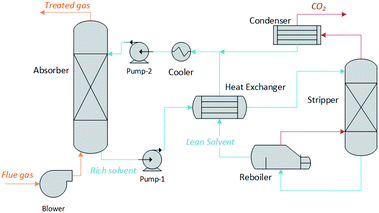
We have developed a software tool for the rapid screening of potential chemical solvents on the basis of their impact on process performance and cost, as opposed to solvent-specific metrics such as CO2 loading or energy of regeneration. Using an archetypal chemisorption process topology, illustrated in Fig. 1, it estimates the size of the units and the energy requirements as a function of the thermochemical characteristics of the solvents. This includes the chemical equilibria description, the mass and energy balances, the solvent and energy requirements, etc. The model involves the computation of non-monetised and monetised process performance indices. The non-monetised indices include the degree of capture, the rate of recovery of the solvent, the height of the absorption column, the area of the heat exchangers and the heat and work requirements of the process. The monetised indices selected include the annualised capital expenditure (CAPEX), operating expenditure (OPEX), and total annual cost (TAC).3.1 Absorption and desorption
The absorber and desorber columns are characterised by the rate of capture nabsi, and the lean loading of the solvent. The columns are represented as rate-based adiabatic packed columns. The model comprises the mass and energy balances, the equilibrium relations, and the rate equations required to describe mass transfer. Non-equilibrium rate-based models show a good agreement with pilot plant data,56–59 in contrast to the results obtained using equilibrium-based models.60 Since the rate-based approach was originally proposed,61,62 and refined,63,64 the trend in the literature has been to develop increasingly detailed models, with some studies going as far as to include rigorous simulations of the reactive absorption in the liquid film, discretizing both the column and the diffusion film.56,65 However, owing to mathematical stiffness, such complex models would be unsuitable for use as a screening tool as is our current focus. Thus, in this study, we have developed a process model which includes a physically based description of heat and mass transfer, but is sufficiently computationally tractable for our purposes.| vinyini − nabsi = voutyouti | (1) |
The mass transfer has been modelled following the two-film theory66 as reviewed for carbon capture by Wilcox et al.67 Non-reactive thermodynamic equilibrium is assumed to be attained at the gas–liquid interface. If absorption occurs at low pressure, it can be assumed that it obeys Henry's law, so the molar fraction of the solute at the liquid interface with the physical solvent (x0,Ii), assuming ideal gas and liquid, would be calculated as:
| yIi = Hix0,Ii | (2) |
 | (3) |
 | (4) |
The calculation of the rate of diffusion is ordinarily one of the most computationally intensive elements of an absorption model, typically employing a Maxwell–Stefan formulation. However, in the context of this study, such an approach would run counter to our aim of developing a high throughput screening tool. Thus we include a description of the limiting diffusivity, i.e., the diffusion of the unreacted base to the reaction plane. Therefore, the diffusivity coefficient has been estimated using:
 | (5) |
 | (6) |
The enhancement factor E is defined as the ratio of the average rate of absorption into an agitated liquid in the presence of the reaction to the average rate of absorption without the reaction. Kenig et al. discretised the film region and demonstrated that the chemical reaction occurring at the film considerably enhances the mass transfer of CO2 within the film region.71 In the cases where the reaction is instantaneous, the enhancement factor is only a function of the diffusion, and consequently, dividing the film into segments does not improve the result. Therefore, for these cases when the reaction is instantaneous, the enhancement factor can be estimated by:
 | (7) |
 is the molar concentration of CO2 at the liquid interface, cB is the molar concentration of the binder component, and DLi is the diffusion coefficient of component i in the liquid phase. For a fast pseudo-first order reaction, the enhancement factor can be estimated as:72
 | (8) |
Dimensions of the column. The total number of moles NCO2 absorbed or desorbed in the process column is calculated from the total contact area which is a function of the size of the tower and the type of packing:
| NCO2 = JCO2εa′ATZT | (9) |
The molar flux of CO2 at the interface JCO2 can be therefore calculated using:
 | (10) |
Considering that CO2 reacts across the film, it is reasonable to assume that the concentration of molecular CO2 in the bulk liquid is negligible.71 The 0 indicates that no chemical reaction is considered at the interface, and only physical absorption is occurring. For the fast pseudo-first order, the size of the column can be estimated combining eqn (8)–(10) giving:
 | (11) |
This approach reduces the numerical complexity of the absorption model in order to permit the rapid evaluation of the performance of a sorbent, but still capturing the influence of the reaction kinetics, the mass transfer across the gas–liquid interface, the thermodynamic equilibrium and the hydrodynamics of the packing.
Energy balance equations. The absorber has been modelled as an adiabatic column,61,73 where the gas and the liquid transfer heat through the absorption of CO2 and the vaporisation of water:
 | (12) |
 | (13) |
 | (14) |
Pilot plant experiments show that the temperature across the desorber height can be estimated as the average value between the temperatures of the lean solvent entering the absorber and the rich solvent leaving the absorber74 and therefore, the stripper has been modelled as an isothermal system.75
3.2 Thermodynamic modelling
The solubility of CO2 in alkanolamines is calculated using the equilibrium model proposed by Gabrielsen et al.,76 where the gas is considered ideal, and Henry’s coefficient is combined with the chemical equilibrium constant: | (15) |
 | (16) |
3.3 Heat exchangers
The process model includes two heat exchangers without phase change, i.e., the lean-rich heat exchanger and the lean cooler, and two heat exchangers with phase change, i.e., the condenser and the reboiler. In all cases they have been modelled as shell-and-tube units, with the condenser being considered to be the vertical condenser and the reboiler being modelled as a thermosyphon. The general equation for the heat transfer area is:| Q = UAHEΔTLM | (17) |
 | (18) |
 | (19) |
 is the arithmetic average heat capacity in the range ΔT.
The fluid heat transfer coefficient value depends on the flow regimes, which is a function of the heat exchanger internals and arrangements and on the fluid properties. For turbulent flow, the heat transfer coefficient for the inside fluid has been estimated via:
 | (20) |
 | (21) |
 | (22) |
 | (23) |
The heat transfer coefficient of the shell side is calculated using Kern's method:81
 | (24) |
 | (25) |
 | (26) |
The reboiler has been modelled as a thermosyphon using the model proposed by Chen for forced-convective boiling.83 This method considers that the heat transfer of the boiling stream is the sum of the contribution of convective and nucleate boiling. The convective boiling coefficient can be estimated using eqn (20) corrected by a two-phase flow factor based on the Lockhart–Martinelli two-phase flow parameter.84 The nucleate boiling coefficient is estimated using the Forster and Zuber correlation.85
3.4 Economic indices
A key objective of this work is to relate the cost of the carbon capture plant to the properties of the solvents. Our model uses the Total Annualised Cost (TAC) as the index against which to assess the economic performance of the plant: | (27) |
 | (28) |
| Cabs = 1.281[f1Cb + VpCp + Cp1]CI | (29) |
Cb = 1.218![[thin space (1/6-em)]](https://www.rsc.org/images/entities/char_2009.gif) exp[6.629 + 0.1826(ln exp[6.629 + 0.1826(ln![[thin space (1/6-em)]](https://www.rsc.org/images/entities/char_2009.gif) W) + 0.02297(ln W) + 0.02297(ln![[thin space (1/6-em)]](https://www.rsc.org/images/entities/char_2009.gif) W)2] W)2] | (30) |
| Cp1 = 300D0.7396ZT0.7068 | (31) |
In the case of heat exchangers,
| CHX = 1.218(fdfmfpCb)CI | (32) |
Cb = exp[8.821 − 0.30863(ln![[thin space (1/6-em)]](https://www.rsc.org/images/entities/char_2009.gif) A) + 0.0681(ln A) + 0.0681(ln![[thin space (1/6-em)]](https://www.rsc.org/images/entities/char_2009.gif) A)2] A)2] | (33) |
In both eqn (29) and (32), CI is a cost multiplier to account for the cost of installation and is assigned the value 2.1 and 1.9 for stainless steel absorption columns and heat exchangers, respectively. More details on these equations and their derivation can be found in the work of Couper.86
Thus, it is possible to make a direct connection with solvent thermophysical or kinetic properties and system cost. For example, the viscosity of the solvent influences the diffusivity (eqn (5) and (6)) which, in turn influences the flux (eqn (10)) and the height of the column (eqn (11)). Finally, this dictates the installed cost of the absorber (eqn (29)) and thus the TAC of the entire system (eqn (27)). A thorough evaluation of the sensitivity of key process design variables and TAC to solvent properties is presented in Section 4.
The cost derived from the electricity consumption and from the heat requirements has been estimated separately. The short-run marginal cost (SRMC) of the electricity has been used assuming a price of coal of $50 per tcoal,87 and the price per tonne of CO2 emitted is $70 per tCO2.88 The cost of steam has been estimated using the SRMC assuming that the efficiency of the boiler is 90%. The annualised costs, i.e., annual CAPEX, OPEX and TAC, are then divided by the tonnes of CO2 captured in one year. The costs of compression of the CO2 for transport and storage have not been included in this work. A previous study shows that the cost of CO2 compression and dehydration is on the order of $20–25 per tCO2.89
4 Results and discussion
This section has been structured as follows: we first investigate the effect of a range of thermo-physical and chemical properties of the solvents on selected monetised and non-monetised indices. The minimum set of properties required for solvent evaluation using our methodology are thermodynamic equilibria of CO2, reaction constant(s), viscosity, density, heat capacity, thermal conductivity and surface tension. For this, we evaluate a carbon capture plant treating 900 kg s−1 of flue gas containing 12% (v/v) of CO2 from an 800 MW supercritical pulverised coal power plant (ScPC). We assume that the plant runs for 335 days per year at 100% capacity. The capture rate is set to 90% of the carbon emitted by the power plant. We aim to identify and rank these thermophysical properties that have the most prominent impact on the cost of the capture plant. Then, we explore the trade-offs that these properties have on the monetised indices via a comprehensive sensitivity analysis.Next, we examine in more detail the CO2 transport from the gas phase into the liquid in the absorber by analysing the effect of thermodynamics, reaction kinetics and transport properties on the molar flux across the interface. Furthermore, we study the effect of the concentration of CO2 in the gas phase by analysing how the flux is affected when the flue gas treated comes from a ScPC plant and from a combined cycle gas turbine (CCGT). The concentration of CO2 in the CCGT is assumed to be 4% (v/v). Finally, we compare the process performance of the carbon plant dedicated to treat the flue gas from that of a ScPC with that of CCGT considering the same net power output for both power plants.
We have selected 30 wt% MEA as the benchmark solvent. Table 1 shows its properties at 303 K. Our model assumes that the coefficient between the new value and that of the benchmark is constant across the temperature range studied. That is, if the property doubles at 303 K with respect to the benchmark, it also doubles at 393 K. We have fixed the rich loading to 0.47 and the lean loading to 0.3. The results show that the TAC of the capture process is $51 per tCO2, which gives a total cost of the CO2 capture of $73 per tCO2 once the costs of CO2 compression and dehydration are accounted for.89 This is in line with current projections of the cost of carbon capture on an industrial scale,90 for example, the Petra Nova Carbon Capture Project, whose cost has been estimated to be $70 per tCO2.91
| Property | Value |
|---|---|
| Equilibrium constant (kPa) | 0.015 |
| Henry's coefficient (kPa m−3 kmol−1) | 4560 |
| Reaction constant (m3 kmol−1 s−1) | 8008 |
| Density (kg m−3) | 1168 |
| Viscosity (mPa s) | 2.51 |
| Heat capacity (kJ kmol−1 s−1) | 89.7 |
| Thermal conductivity (kJ m−1 s−1 K−1) | 4.75 × 10⁻⁴ |
4.1 Evaluation of the thermophysical properties of solvents
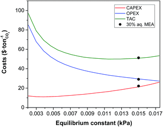
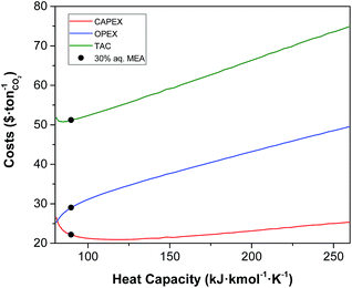
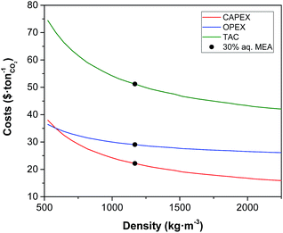
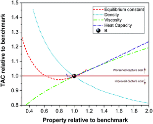
Using our modelling tool, we have identified the following properties that can affect the process performance of the carbon capture: density, viscosity, surface tension, heat capacity, thermal conductivity, heat of absorption which might inherently include the heat of reaction in the case of reactant solvents, and CO2 solubility, which might be expressed in terms of loading, Henry's coefficient or a generic equilibrium constant. A sensitivity analysis has been carried out to determine the aftermaths of varying each of the aforementioned properties on the annualised CAPEX, OPEX and TAC of the carbon capture plant. Every property has been screened individually by varying its value within sensible ranges that were selected based on typical values of solvents.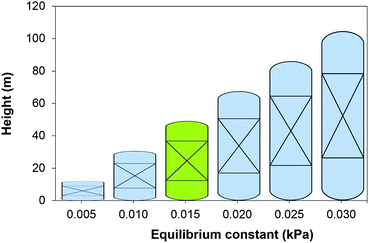 | ||
| Fig. 2 Height of the absorber as a function of the chemical equilibrium constant of the solvent at 303 K. Green figure corresponds to the height of an absorber using 30 wt% MEA. | ||
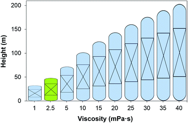 | ||
| Fig. 4 Height of the absorber as a function of the viscosity of the solvent at 303 K. Green figure corresponds to the height of an absorber using 30 wt% MEA. | ||
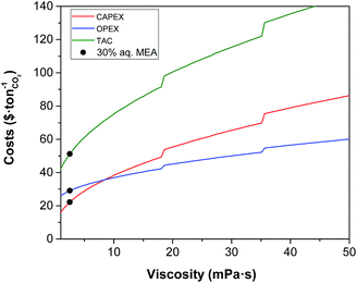 | ||
| Fig. 5 Effect of viscosity on the annualised CAPEX, the OPEX and the TAC of the carbon capture plant. | ||
Higher values of viscosity increase pump power as a result of changes in the hydraulic behaviour of the solvent associated with a higher friction factor and pressure drop, thus increasing the operational challenges. Yang et al. reported that a mixture of aqueous MEA with an ionic liquid blocked the pipelines and their pumps stopped operating when they used a mixture with a viscosity of 16 mPa s.95 However, the cost related to the electric requirements represents 5% of the total OPEX of the process. Thus, an increase in plant electricity requirements does not correspond to a significant increase in process costs. The results show that the cost of the electric requirements is $1 per tCO2 at the viscosity of the benchmark, whereas at 40 mPa s the cost is $2.7 per tCO2 relative to an operating cost of $56 per tCO2 at this viscosity; a negligible amount.
In the next sections we explore the trade-offs between the viscosity, the equilibrium constant and the heat capacity. Frequently, the effort to design solvents with a higher CO2 leads to chemical structures that contain atoms or functional groups that not only interact more efficiently with the CO2 but also present intra- or intermolecular interactions, increasing the viscosity of the system. Fig. 9 shows the effect of both properties on the monetised indices of the process. The effect of the viscosity in the flow regime inside the heat exchanger discussed above (see Fig. 5) is captured again in Fig. 9.
 | ||
| Fig. 9 Trade-offs between the equilibrium constant and the viscosity on annualised CAPEX, OPEX and TAC. The value represented here correspond to that at the top of the absorber, i.e., 303 K. | ||
The discontinuity of the evolution of the CAPEX with the viscosity corresponds to the points where the flux transitions from turbulent to laminar in the heat exchangers. Interestingly, the heat capacity can displace the laminar regime front towards lower viscosities, as shown in Fig. 10. At the heat capacity of the benchmark, the first transit to laminar flow in the cooler occurs at viscosities 7 times higher than the viscosity of the benchmark. When the heat capacity doubles, the laminar front is found at 4.5 times the viscosity of the benchmark. This is an important observation as the heat capacity is usually overlooked in the screening, selection and design of solvents for carbon capture.
4.2 The competition between equilibrium, transport and kinetic properties
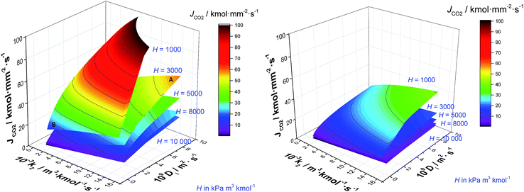
The absorption column might be considered the core of the capture process. Thus, solvent selection is particularly important here. A solvent with high CO2 capacity per unit volume will serve to reduce the amount of solvent required, reducing both the CAPEX and the OPEX. Moreover, the foregoing results emphasise the importance of maximising rates of mass transfer in order to reduce the size and capital cost associated with the absorption column. Gas–liquid interphase mass transfer is a complex function of simultaneous transport and thermodynamic driven phenomena occurring across and at both sides of the interface. This includes the transport of the CO2 through the gas–liquid interface, and then its diffusion entangled with the chemical reaction towards the bulk liquid. Understanding the contribution of the different parameters that determine the rate at which CO2 is transferred from the gas to the liquid phase is imperative for the design of new solvents.67Fig. 11 shows the contrasting impact of diffusivity (D) and reaction constant (k2) for five different archetypal solvents with Henry's coefficients of 1000, 3000, 5000, 8000 and 10![[thin space (1/6-em)]](https://www.rsc.org/images/entities/char_2009.gif) 000 kPa m3 kmol−1, for an exhaust gas of 12 mol% (left) and 4 mol% (right) respectively. Note that by definition, Henry's coefficient and gas solubility are inversely related. Solvents with particularly high CO2 solubility are represented by H = 1000 kPa m3 kmol−1, whereas low CO2 solubility solvents usually present Henry's coefficient values higher than 104 kPa m3 kmol−1. In the case of the high gas-phase CO2 concentration, it is evident that liquid phase diffusivity is the rate limiting step in the absorption of CO2, with reaction kinetics playing a secondary role. This is in line with previous results,96 and reinforces the typical approximation of treating chemical reactions in these systems as equilibrium, as opposed to using a full reaction kinetic description. However, if a solvent has a lower CO2 solubility, then the influence of diffusivity and reaction rate is of the same order. To illustrate this, let us perform the following thought experiment with two solvents, solvent A with Henry's coefficient of 3000 kPa m3 kmol−1, and a solvent B with a significant higher CO2 solubility exemplified in Fig. 10 by Henry's coefficient of 1000 kPa m3 kmol−1. Let us assume that solvent A presents a high diffusivity, e.g., 10−8 m2 s−1, and solvent B, which presents a markedly higher CO2 solubility, has a hindered diffusivity coefficient below 10−9 m2 s−1. Solvent A outperforms the CO2 flux of solvent B by 154% despite the lower CO2 capacity because of its favoured transport properties.
000 kPa m3 kmol−1, for an exhaust gas of 12 mol% (left) and 4 mol% (right) respectively. Note that by definition, Henry's coefficient and gas solubility are inversely related. Solvents with particularly high CO2 solubility are represented by H = 1000 kPa m3 kmol−1, whereas low CO2 solubility solvents usually present Henry's coefficient values higher than 104 kPa m3 kmol−1. In the case of the high gas-phase CO2 concentration, it is evident that liquid phase diffusivity is the rate limiting step in the absorption of CO2, with reaction kinetics playing a secondary role. This is in line with previous results,96 and reinforces the typical approximation of treating chemical reactions in these systems as equilibrium, as opposed to using a full reaction kinetic description. However, if a solvent has a lower CO2 solubility, then the influence of diffusivity and reaction rate is of the same order. To illustrate this, let us perform the following thought experiment with two solvents, solvent A with Henry's coefficient of 3000 kPa m3 kmol−1, and a solvent B with a significant higher CO2 solubility exemplified in Fig. 10 by Henry's coefficient of 1000 kPa m3 kmol−1. Let us assume that solvent A presents a high diffusivity, e.g., 10−8 m2 s−1, and solvent B, which presents a markedly higher CO2 solubility, has a hindered diffusivity coefficient below 10−9 m2 s−1. Solvent A outperforms the CO2 flux of solvent B by 154% despite the lower CO2 capacity because of its favoured transport properties.
The typical flue gas from a coal plant contains 10–15% (v/v) of CO2, whereas the content of CO2 of the flue gas from a gas plant is 3–5% (v/v). The impact that this much more dilute exhaust gas has on solvent performance is illustrated in Fig 10b. In this context, the dominance of Henry's constant and liquid phase diffusivity on the rate of CO2 absorption is effectively eliminated. Here, each of CO2 solubility, diffusivity and chemical kinetics plays approximately equivalent roles. This implies that retaining the kinetics in sorbent screening is important and that treating these reactions as equilibrium is likely to be a poor approximation.
5 Conclusions
We have presented a process performance indexed methodology to assess the potential of chemical solvents for carbon capture. Monetised (e.g., CAPEX, OPEX and TAC) and non-monetised (e.g., equipment size) KPIs are evaluated as a function of the selected KOPs of the process and the characteristics of the solvent. The KOPs include the solvent flow rate as a function of the exhaust gas composition, the rate of absorption and the SRMC of the steam available. The characteristics of the solvent are the kinetics of the reaction, the thermodynamic, and physico-chemical properties and the transport properties of the solvent, i.e., reaction constant, equilibrium constant, heat of reaction, molecular weight, density, heat capacity, viscosity, thermal conductivity and surface tension of the solvent. Historically, most effort on solvent development has focused on enhancing the CO2 absorption and reducing the heat of reaction, neglecting the effect of other properties on the process cost, particularly on the capital cost contribution to the overall cost of CO2 capture ($ per tCO2). The properties that have a primary importance for the TAC of CO2 capture are, in order of prominence:(1) Viscosity
(2) Equilibrium loading of CO2
(3) Reaction kinetics
(4) Heat capacity
(5) Heat of absorption
(6) Density
(7) Surface tension
It must be recognised that, of these, the first three properties are significantly more important than the other four. The fact that solvent viscosity is found to be of primary importance confirms our hypothesis that, in order to rationally screen, select and design sorbents for chemical processes in general, and CO2 capture in particular, a whole system approach is necessary. Otherwise, it is impossible to fully appreciate the impact of solvent thermophysical properties on process performance and therefore costs. The absence of such an approach to date has led to an over emphasis of CO2 solubility in solvent selection and design, potentially limiting progress in this area. One of the main drawbacks to a “designer solvent” approach is the impact of solvent functionalisation on physical properties, or the unintended consequences that may accompany a sole emphasis on CO2 capacity. Greater chemical functionalisation of molecular liquids almost inevitably leads to a rapid increase in viscosity, and a concomitant decrease in thermal and chemical stabilities. While the density of functionalised solvents is normally higher, our model identifies this as a minor impact, and is likely offset by the inevitable increase in heat of absorption and therefore regeneration energy. Our model clearly demonstrates that this creates an ever greater pressure on increased solubility to offset the reduced mass transport, thereby leading to a “death spiral” of offsetting improvements in one property at the expense of another. Only a systematic approach to solvent design, with all properties appropriately weighted, can lead to an optimal (or possibly even improved) solvent design.
Conflicts of interest
There are no conflicts to declare.Acknowledgements
The authors thank the United Kingdom Carbon Capture and Storage Research Council (UKCCSRC) (Grant No. UKCCSRC-199) for funding this work. The authors are grateful to P. Brandl for proof reading the manuscript and assistance with figures.References
- IPCC, Climate Change 2014: Mitigation of Climate Change: Contribution of Working Group III to the Fifth Assessment Report of the Intergovernmental Panel on, Cambridge University Press, 2014, p. 1132 Search PubMed.
- The Global Status of CCS, Summary report, 2016, https://www.globalccsinstitute.com/publications/global-status-ccs-2016-summary-report Search PubMed.
- Global CCS Institute, Large Scale CCS Projects, 2017, https://goo.gl/Wv0Vk7 Search PubMed.
- Cost and Performance of Carbon Dioxide Capture from Power Generation, IEA technical report, 2011 Search PubMed.
- Carbon Capture & Storage: Assessing the Economics, Mckinsey climate change initiative technical report, 2008 Search PubMed.
- R. Oxburgh, Lowest Cost Decarbonisation for the UK: The Critical Role of CCS. Report to the Secretary of State for Business, Energy and Industrial Strategy from the Parliamentary Advisory Group on Carbon Capture and Storage, 2016, https://goo.gl/Afoyih Search PubMed.
- L. A. Hackett, Commercialisation of CCS – What needs to happen?, 2016, https://tinyurl.com/y7mxxsu8 Search PubMed.
- A. Samanta, A. Zhao, G. K. H. Shimizu, P. Sarkar and R. Gupta, Ind. Eng. Chem. Res., 2012, 51, 1438–1463 CrossRef CAS.
- J. Wang, L. Huang, R. Yang, Z. Zhang, J. Wu, Y. Gao, Q. Wang, D. O'Hare and Z. Zhong, Energy Environ. Sci., 2014, 7, 3478–3518 CAS.
- R. Ben-Mansour, M. A. Habib, O. E. Bamidele, M. Basha, N. A. A. Qasem, A. Peedikakkal, T. Laoui and M. Ali, Appl. Energy, 2016, 161, 225–255 CrossRef CAS.
- A. E. Creamer and B. Gao, Environ. Sci. Technol., 2016, 50, 7276–7289 CrossRef CAS PubMed.
- D. Clodic, R. El Hitti, M. Younes, A. Bill and F. Casier, 4th Annual Conference on Carbon Capture & Sequestration, 2005, pp. 2–5 Search PubMed.
- M. J. Tuinier, M. van Sint Annaland, G. J. Kramer and J. A. M. Kuipers, Chem. Eng. Sci., 2010, 65, 114–119 CrossRef CAS.
- E. J. Anthony, Ind. Eng. Chem. Res., 2008, 47, 1747–1754 CrossRef CAS.
- I. Martínez, R. Murillo, G. Grasa and J. Carlos Abanades, AIChE J., 2011, 57, 2599–2607 CrossRef.
- J. Adanez, A. Abad, F. Garcia-Labiano, P. Gayan and L. F. de Diego, Prog. Energy Combust. Sci., 2012, 38, 215–282 CrossRef CAS.
- P. S. Fennell and B. Anthony, Calcium and Chemical Looping Technology for Power Generation and Carbon Dioxide (CO2) Capture, Elsevier Ltd., 2015 Search PubMed.
- R. Khalilpour, K. Mumford, H. Zhai, A. Abbas, G. Stevens and E. S. Rubin, J. Cleaner Prod., 2015, 103, 286–300 CrossRef CAS.
- N. Mac Dowell, N. Florin, A. Buchard, J. Hallett, A. Galindo, G. Jackson, C. S. Adjiman, C. K. Williams, N. Shah and P. Fennell, Energy Environ. Sci., 2010, 3, 1645–1669 CAS.
- M. E. Boot-Handford, J. C. Abanades, E. J. Anthony, M. J. Blunt, S. Brandani, N. Mac Dowell, J. R. Fernández, M.-C. M.-C. Ferrari, R. Gross, J. P. Hallett, R. S. Haszeldine, P. Heptonstall, A. Lyngfelt, Z. Makuch, E. Mangano, R. T. J. Porter, M. Pourkashanian, G. T. Rochelle, N. Shah, J. G. Yao and P. S. Fennell, Energy Environ. Sci., 2014, 7, 130–189 CAS.
- J. C. Abanades, B. Arias, A. Lyngfelt, T. Mattisson, D. E. Wiley, H. Li, M. T. Ho, E. Mangano and S. Brandani, Int. J. Greenhouse Gas Control, 2015, 40, 126–166 CrossRef CAS.
- J. Oexmann and A. Kather, Int. J. Greenhouse Gas Control, 2010, 4, 36–43 CrossRef CAS.
- A. Chremos, E. Forte, V. Papaioannou, A. Galindo, G. Jackson and C. S. Adjiman, Fluid Phase Equilib., 2016, 407, 280–297 CrossRef CAS.
- R. R. Bottoms, US Pat., application 1783901, 1930.
- P. M. M. Blauwhoff, G. F. Versteeg and W. P. M. Van Swaaij, Chem. Eng. Sci., 1984, 39, 207–225 CrossRef CAS.
- F.-Y. Jou, A. E. Mather and F. D. Otto, Can. J. Chem. Eng., 1995, 73, 140–147 CrossRef CAS.
- T. G. Amundsen, L. E. Øi and D. A. Eimer, J. Chem. Eng. Data, 2009, 54, 3096–3100 CrossRef CAS.
- A. Belabbaci, A. Razzouk, I. Mokbel, J. Jose and L. Negadi, J. Chem. Eng. Data, 2009, 54, 2312–2316 CrossRef CAS.
- K. Klepáčová, P. J. G. Huttenhuis, P. W. J. Derks and G. F. Versteeg, J. Chem. Eng. Data, 2011, 56, 2242–2248 CrossRef.
- I. Kim and H. F. Svendsen, Ind. Eng. Chem. Res., 2007, 46, 5803–5809 CrossRef CAS.
- Y. E. Kim, J. A. Lim, S. K. Jeong, Y. I. Yoon, S. T. Bae and S. C. Nam, Bull. Korean Chem. Soc., 2013, 34, 783–787 CrossRef CAS.
- I. Kim, K. A. Hoff, E. T. Hessen, T. Haug-Warberg and H. F. Svendsen, Chem. Eng. Sci., 2009, 64, 2027–2038 CrossRef CAS.
- G. Sartori and D. W. Savage, Ind. Eng. Chem. Fundam., 1983, 22, 239–249 CAS.
- P. Singh, J. P. M. Niederer and G. F. Versteeg, Int. J. Greenhouse Gas Control, 2007, 1, 5–10 CrossRef CAS.
- P. Singh, J. P. Niederer and G. F. Versteeg, Chem. Eng. Res. Des., 2009, 87, 135–144 CrossRef CAS.
- P. Singh and G. F. Versteeg, Process Saf. Environ. Prot., 2008, 86, 347–359 CrossRef CAS.
- G. Puxty, R. Rowland, A. Allport, Q. Yang, M. Bown, R. Burns, M. Maeder and M. Attalla, Environ. Sci. Technol., 2009, 43, 6427–6433 CrossRef CAS PubMed.
- D. Bonenfant, M. Mimeault and R. Hausler, Ind. Eng. Chem. Res., 2003, 42, 3179–3184 CrossRef CAS.
- S. Bishnoi and G. T. Rochelle, Chem. Eng. Sci., 2000, 55, 5531–5543 CrossRef CAS.
- T. Charkravarty, Chem. Eng. Prog., 1985, 81, 32–36 Search PubMed.
- H. Bosch, G. F. Versteeg and W. P. M. Van Swaaij, Chem. Eng. Sci., 1989, 44, 2745–2750 CrossRef CAS.
- D. A. Glasscock, J. E. Critchfield and G. T. Rochelle, Chem. Eng. Sci., 1991, 46, 2829–2845 CrossRef CAS.
- M. S. DuPart, P. C. Rooney and T. R. Bacon, Hydrocarbon Process., 1999, 78(4), 81–86 CAS.
- L. Raynal, P. Alix, P. A. Bouillon, A. Gomez, M. Le Febvre De Nailly, M. Jacquin, J. Kittel, A. Di Lella, P. Mougin and J. Trapy, Energy Procedia, 2011, 779–786 CrossRef CAS.
- U. Liebenthal, D. D. D. Pinto, J. G. M.-S. Monteiro, H. F. Svendsen and A. Kather, Energy Procedia, 2013, 37, 1844–1854 CrossRef CAS.
- S. Want and Z. Xu, in Absorption-Based Post-Combustion Capture of Carbon Dioxide, ed. P. Feron, Elsevier Science, 2016 Search PubMed.
- O. Aschenbrenner and P. Styring, Energy Environ. Sci., 2010, 3, 1106–1113 CAS.
- M. Ramdin, T. W. de Loos and T. J. H. Vlugt, Ind. Eng. Chem. Res., 2012, 51, 8149–8177 CrossRef CAS.
- E. D. Bates, R. D. Mayton, I. Ntai and J. H. Davis, J. Am. Chem. Soc., 2002, 124, 926–927 CrossRef CAS PubMed.
- M. T. Mota-Martinez, M. Althuluth, M. C. Kroon and C. J. Peters, Fluid Phase Equilib., 2012, 332, 35–39 CrossRef CAS.
- L. F. Zubeir, M. H. M. Lacroix and M. C. Kroon, J. Phys. Chem. B, 2014, 118, 14429–14441 CrossRef CAS PubMed.
- D. Shaw, Energy Procedia, 2009, 1, 237–246 CrossRef CAS.
- D. G. Chapel, C. L. Mariz and J. Ernest, Canadian Society of Chemical Engineers Annual Meeting, 1999 Search PubMed.
- Y. Yagi, T. Mimura, T. Yonekawa and R. Yoshiyama, GHGT-8, 2006 Search PubMed.
- S. Holton, Eight Annual Conferences on Carbon Capture and Sequestration, 1999 Search PubMed.
- N. Asprion, Ind. Eng. Chem. Res., 2006, 45, 2054–2069 CrossRef CAS.
- C. Kale, A. Górak and H. Schoenmakers, Int. J. Greenhouse Gas Control, 2013, 17, 294–308 CrossRef CAS.
- N. Mac Dowell, N. J. Samsatli and N. Shah, Int. J. Greenhouse Gas Control, 2013, 12, 247–258 CrossRef CAS.
- N. Mac Dowell and N. Shah, Int. J. Greenhouse Gas Control, 2014, 27, 103–119 CrossRef CAS.
- A. Lawal, M. Wang, P. Stephenson and H. Yeung, Fuel, 2009, 88, 2455–2462 CrossRef CAS.
- R. E. Treybal, Ind. Eng. Chem., 1969, 61, 36–41 CrossRef CAS.
- H. M. Feintuch and R. E. Treybal, Ind. Eng. Chem. Process Des. Dev., 1978, 17, 505–513 CAS.
- R. Krishnamurthy and R. Taylor, AIChE J., 1985, 31, 449–456 CrossRef CAS.
- R. Krishnamurthy and R. Taylor, AIChE J., 1985, 31, 456–465 CrossRef CAS.
- E. Y. Kenig, R. Schneider and A. Górak, Chem. Eng. Sci., 2001, 56, 343–350 CrossRef CAS.
- W. K. Lewis and W. G. Whitman, Ind. Eng. Chem., 1924, 16, 1215–1220 CrossRef.
- J. Wilcox, P. Rochana, A. Kirchofer, G. Glatz and J. He, Energy Environ. Sci., 2014, 7, 1769 CAS.
- K. Onda, H. Takeuchi and Y. Okumoto, J. Chem. Eng. Jpn., 1968, 1, 56–62 CrossRef CAS.
- C. R. Wilke and P. Chang, AIChE J., 1955, 1, 264–270 CrossRef CAS.
- E. D. Snijder, M. J. M. te Riele, G. F. Versteeg and W. P. M. van Swaaij, J. Chem. Eng. Data, 1993, 38, 475–480 CrossRef CAS.
- E. Kenig, R. Schneider and A. Górak, Chem. Eng. Sci., 1999, 54, 5195–5203 CrossRef CAS.
- D. W. van Krevelen and P. J. Hoftijzer, Chem. Eng. Prog., 1948, 44, 529–536 CAS.
- J. Pandya, Chem. Eng. Commun., 1983, 19, 343–361 CrossRef CAS.
- F. A. Tobiesen, O. Juliussen and H. F. Svendsen, Chem. Eng. Sci., 2008, 63, 2641–2656 CrossRef CAS.
- B. Huepen and E. Y. Kenig, Ind. Eng. Chem. Res., 2010, 49, 772–779 CrossRef CAS.
- J. Gabrielsen, M. L. Michelsen, E. H. Stenby and G. M. Kontogeorgis, Ind. Eng. Chem. Res., 2005, 44, 3348–3354 CrossRef CAS.
- A. Penttilä, C. Dell'Era, P. Uusi-Kyyny and V. Alopaeus, Fluid Phase Equilib., 2011, 311, 59–66 CrossRef.
- S. S. Laddha, J. M. Diaz and P. V. Danckwerts, Chem. Eng. Sci., 1981, 36, 229–230 CrossRef.
- G. F. Versteeg, P. M. M. Blauwhoff and W. P. M. van Swaaij, Chem. Eng. Sci., 1987, 42, 1103–1119 CrossRef CAS.
- S. J. Park, H. Y. Shin, B.-M. Min, A. Cho and J.-S. Lee, Korean J. Chem. Eng., 2009, 26, 189–192 CrossRef CAS.
- D. Q. Kern, Process Heat Transfer, McGraw-Hill, New York, 1950, p. 871 Search PubMed.
- R. K. Sinnott, in Coulson and Richardson's Chemical Engineering, Butterworth-Heinemann, Oxford, 4th edn, 2005, ch. Heat-Trans Search PubMed.
- J. C. Chen, Ind. Eng. Chem. Process Des. Dev., 1966, 5, 322–329 CAS.
- R. Lockhart and R. Martinelli, Chem. Eng. Prog., Symp. Ser., 1949, 45, 39–48 Search PubMed.
- H. K. Forster and N. Zuber, AIChE J., 1955, 1, 531–535 CrossRef CAS.
- J. R. Couper, in Chemical Process Equipment Selection and Design, ed. J. R. Couper, Butterworth-Heinemann, 2nd edn, 1990, ch. 21 Cost, pp. 663–690 Search PubMed.
- A. Annut, Prices of fuels purchased by major power producers, 2016, https://www.gov.uk/government/statistical-data-sets/prices-of-fuels-purchased-by-major-power-produce Search PubMed.
- N. Mac Dowell and N. Shah, Comput. Chem. Eng., 2015, 74, 169–183 CrossRef CAS.
- C. Kolster, E. Mechleri, S. Krevor and N. Mac Dowell, Int. J. Greenhouse Gas Control, 2017, 58, 127–141 CrossRef CAS.
- E. S. Rubin, J. E. Davison and H. J. Herzog, Int. J. Greenhouse Gas Control, 2015, 40, 378–400 CrossRef CAS.
- E. Crooks, World's biggest carbon capture project on schedule, 2017, https://www.ft.com/content/eee0d5d6-d700-11e6-944b-e7eb37a6aa8e?mhq5j=e3 Search PubMed.
- P. M. Mathias, K. Afshar, F. Zheng, M. D. Bearden, C. J. Freeman, T. Andrea, P. K. Koech, I. Kutnyakov, A. Zwoster, A. R. Smith, P. G. Jessop, O. G. Nik and D. J. Heldebrant, Energy Environ. Sci., 2013, 6, 2233–2242 CAS.
- P. M. Mathias and J. P. O'Connell, Ind. Eng. Chem. Res., 2012, 51, 5090–5097 CrossRef CAS.
- A. Zakeri, A. Einbu, P. O. Wiig, L. E. Øi and H. F. Svendsen, Energy Procedia, 2011, 4, 606–613 CrossRef CAS.
- J. Yang, X. Yu, L. An, S.-T. Tu and J. Yan, Appl. Energy, 2017, 194, 9–18 CrossRef CAS.
- S. Freguia and G. T. Rochelle, AIChE J., 2003, 49, 1676–1686 CrossRef CAS.
- International Energy Agency, CO2 emissions from fuel combustion highlights. 2015 Edition, International energy agency technical report, 2015 Search PubMed.
Footnotes |
| † The CO2 capture plants for power generation in operation at the time of writing in 2017 are Boundary Dam in Canada and Petra Nova in United States. The capture method in both cases is chemical absorption using amine.3 |
| ‡ 40 Mtpa will be captured with the new capacity installed in 2017. The capacity required by 2040 is 4000 Mtpa2. |
| § All costs are calculated in 2010 USD. |
| ¶ This value can range between 1.7 for carbon steel and up to 7.7 for titanium. |
| || This value could be increased if a more corrosive solvent were to be used. |
| This journal is © The Royal Society of Chemistry 2017 |

