 Open Access Article
Creative Commons Attribution 3.0 Unported Licence
SURMOF induced polymorphism and crystal morphological engineering of acetaminophen polymorphs: advantage of heterogeneous nucleation†
Geetha
Bolla
 and
Allan S.
Myerson
 *
*
Department of Chemical Engineering, Massachusetts Institute of Technology, 77 Massachusetts Avenue, E19-502b, Cambridge, Massachusetts 02139, USA. E-mail: myerson@mit.edu
First published on 14th March 2018
Abstract
Self-assembled monolayers are extended to SURMOFs as template hetero surfaces using a basic HKUST-1 MOF. The concept of MOF induced polymorphism with morphological engineering adapted to crystal engineering has shown to have the advantage of heterogeneous nucleation. The substrates are used to study the nucleation and growth of acetaminophen, and have resulted in metastable polymorphs which are of a desirable form with block morphology.
Polymorphic screening and crystal morphology engineering of organic molecules have been studied extensively in the last few decades through multiple methods. However, a fundamental understanding of heterogeneous nucleation on molecular surfaces has been challenging and has increased interest from the pharmaceutical industry as well as in materials science and optoelectronics due to the potential applications.1,2 Despite the fact that self-assembled monolayers (SAMs)3 are a well-established method used to form various less stable polymorphs or crystalline shapes (different faces), results are often not practical due to the limitation in contribution to the total surface.4 Hence, polymer and gel induced polymorphic studies were introduced recently and showed advantages over solution crystallization; however they are often limited in either morphology or polymorphic yield and a detailed explanation of the causes/mechanisms are still unclear.5–9 Finding a new one-pot method with a new design surface is important and becomes a daunting task in the field, in particular to obtain metastable polymorphs. In this study, we were successful with our newly designed surface and have shown its advantages with an example drug, acetaminophen (N-acetyl-para-aminophenol, APAP). We discuss the formation of the less stable polymorph of APAP and the morphology changes using a new developed substrate, in this case a surface metal organic framework (SURMOF).10–12 SURMOFs are combinations of SAMs and metal organic frameworks (MOFs)13,14 on surfaces. They have been studied recently with potential different applications such as in photovoltaics, CO2 reduction, memory devices, supercapacitors and batteries.10 However, SURMOFs have not yet been explored in the application of polymorph screening. The advantage of controlled orientation of the MOFs on the basis of the starting SAM functional group can allow orientational growth of target functional organic molecules and can lead to different nucleation paths and different growth directions (Scheme 1). As MOFs are highly porous crystalline materials, their impact on and contribution to the surface as a heterogeneous layer is quite effective compared to the usual SAM surface. With this idea we began our studies and have shown here how a SURMOF can be influential in attaining a less stable polymorph.
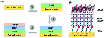 | ||
| Scheme 1 (a) A SURMOF showing the heterogeneous substrate designed steps with multi-layers. (b) Structural display of the multi-layers with the base Au, SAM, MOF and APAP structures. | ||
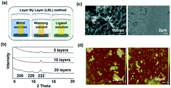
Template SURMOF nucleation studies of APAP involved three major steps (Scheme 1): preparation of SAM, addition of the SURMOF substrate and then crystallization of APAP. As the first step is SAM preparation, gold substrates were first functionalized with 12-mercaptododecanoic acid (12-COOH) by a reported method.4 In the second step, a well-known reported HKUST-1 MOF thin film, which consists of trimesic acid (H3BTC) and copper acetate, was prepared by layer-by-layer dipping (LBL-D)10 with an optimal number of 10 layers (Fig. 1a, and the experimental procedure is in the ESI†). The structure of the MOF contains a paddle wheel 3D coordinated porous polymer with 69.2 and 42.5% of contact void and solvent accessible contact space, respectively. The uniform structure of the pristine SURMOF was confirmed by thin film X-ray diffraction, the 2θ values of the films at 6.7, 9.5 and 11.5 of the {100}, {110} and {111} faces, respectively, are shown in Fig. 1b and in S4a in the ESI,† and the bulk powder form of the MOF HKUST-1 was confirmed in the reported (CCDC, Refcode: DOTSOV42) structure. Despite the confirmation by XRD, we further analysed the surface and particle size/distribution of the SURMOFs by SEM and AFM (Fig. 1c and d, and S1 and S2 in the ESI†) and showed the thin film surface at the nanometre scale with porous surface homogenous distribution. Following this, surface analysis at selected areas on two different films confirmed the phase purity and height distribution, and showed a thickness in the range of 200–400 nm (Fig. 1d, and S2 in the ESI†). We also used one further technique, EDAX elemental analysis using elemental Cu, to confirm the distribution of the MOF, which showed a uniform distribution (Fig. S3 in the ESI†). The thickness of the film was intentionally prepared below micrometre height to allow for the growth of APAP crystals of several micrometres in size that would be suitable for single crystal face indexing experiments. These SURMOF substrates were designed to investigate how template functionalization of the inorganic, ordered and highly porous MOF can influence the nucleation of acetaminophen (APAP).
APAP was chosen as an example and was crystallized with the SURMOF templates as a proof-of-concept to continue with the third step, as it is a well-known active pharmaceutical ingredient (an API, used as an analgesic and antipyretic drug) and is known to crystallize in three polymorphic forms:15–21 form I, which is less soluble and exhibits poor tabletting compaction compared to form II, form II and another metastable form III. Nichols, et al. and Ristic, et al. reported that forms I and II crystalize concomitantly in solution crystallization,16,17 and that form II was reported as needles whereas form I was reported as blocks and prisms. The reproducibility of form II from solution crystallization still remains a challenge, but melt crystallization or the use of an additive can perhaps produce form II, but these methods are not suitable for processing. In the present study, we showed that crystal nucleation on the porous surface of the HKUST-1 SURMOF contributed significantly to unique nucleation kinetics, allowed for metastable phase stabilization and engineered the SURMOF with block morphology providing a dual advantage. This successful demonstration of MOF induced heterogeneous nucleation will allow for a new approach and open up new challenges for metastable polymorph discovery along with inherent morphology differences based on complementary interactions at the SURMOF interface.
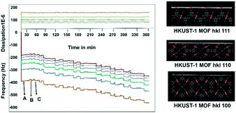
Before starting the third step, the nucleation of APAP on the SURMOF, it was worthwhile to check the complexation of the MOF and APAP. This would provide us with a better understanding of the effect of surface nucleation versus a solution interaction on both the polymorph and morphology. Slurry experiments were carried out for 6 h and the residue was compared with the pure MOF (Fig. S4a in the ESI†), which confirmed no complexation occurred between the HKUST-1 MOF and APAP. Then, in situ monitoring of time-dependent frequency vs. dissipation was carried out at different cell frequencies to understand the quantitative mass transfer with continuous uptake (Fig. 2). Three different quartz crystal microbalances with dissipation22,23 (QCM-D, a flow cell adsorption measurement experiment) cell experiments were performed. First, the QCM-D cell experiment without a modified substrate (bare Au) surface was performed (Fig. S5a in the ESI†), then a modified SAM containing both a metal and a ligand was tested (Fig. S5b in the ESI†), and then finally a modified QCM-D-SAM cell with a metal and a ligand in addition to APAP (each separate step was washed with EtOH) was studied to monitor the weak topo-chemical interactions of the MOF with APAP in solution (Fig. 2). Here, we observed that without SAM (unmodified empty gold substrate) MOF formation was not successful, as removal of the metal and ligand occurred during the washing step (Fig. S5a in the ESI†), whereas when the substrate was modified with SAM, a continuous load of layers with uniform dissipation was observed (Fig. S5b in the ESI†). Finally, three layers of deposition were performed, and observed continuous loading confirmed possible weak interactions between the MOF and APAP in solution.
For the third step, crystallization experiments of APAP at different concentrations (1–10 mg mL−1) were performed. In order to analyse the controlled growth of APAP polymorphs and their morphology, solution evaporation-liquid phase epitaxy (SE-LPE) and liquid phase epitaxy drop casting (LPE-DC) methods were used (Fig. S7a in the ESI†). Forms I and II crystallize in a monoclinic (P21/c) and orthorhombic (Pbca) manner, respectively, with lattice coordinates a = 7.0661(6), b = 9.3366(7), c = 11.6508(9), β = 97° and a = 11.7552(3), b = 7.13941(11), c = 17.1714(2) being well reported in the literature.15,16 Their 2D packing suggests that the APAP self-assembled via N–H⋯O, O–H⋯O hydrogen bonds at different angles (form I = 77°, II = 5° as shown in Fig. S6 in the ESI†) and consists of a four membered LSAM24 motif R44(22).25 Here too we reported the single crystal analysis of form II and the crystallographic details are displayed in Table S4 of the ESI.† As we mentioned earlier, considering all previous studies, it has been consistently reported that the morphology of form I is block and that of form II is needle in any given crystallization, which is consistent with the literature until now (Table S1 in the ESI†). Indeed, form I exhibits a profound change in the growth direction depending on solvent, saturation and starting substrate in the case of epitaxial growth. Form I crystallizes in EtOH and H2O in a prismatic habit as pinacoids (101) and prisms (110), and in epitaxial growth with organic excipients the (001) face predominates.20 In general it is not expected that form II will exhibit block morphology rather than needles. The major incentive to produce form II stems from the fact that it undergoes plastic deformation and is suitable for direct compression in the manufacturing of pharmaceutical tablets, and so attracts more commercial interest than form I. The role of tailor-made additives and solvents to control nucleation and morphology due to the selective adsorption of the faces based on supramolecular hetero intersections has been studied with numerous examples in the last three decades.1,26,27 Here we introduced a new method using a SURMOF with APAP as an example. In addition, attachment energy (Eatt = Ecryst + Eslice) calculations of form I were performed (Table S3 in the ESI†), showing that the major faces are (011), (10−1), (002), (101), (110) and (11−1) with resulting attachment energies of −52.142, −67.612, −80.566, −53.107, −69.325, −73.612 and −54.437 kcal mol−1, respectively, and the suggested, morphological importance of the form I faces (011) and (101) is assumed to be greater than that of the other faces, which follow less order. Ristic et al. reported form I growth from aqueous solution with a dominant (110) face from lower to higher supersaturation and showed that the solvent directed the growth.17
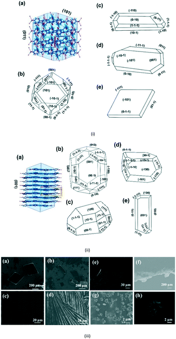
Here, Liquid Phase Epitaxy Drop Casting (LPE-DC) and Solution Evaporation-Liquid Phase Epitaxy (SE-LPE) methods were used to grow crystals and at select places such as on the top, on the edge, and on the rest of the substrate, the grown crystals were chosen for face indexing. Fig. 3i-a shows the 2D interaction of form I with BFDH model faces, corroborating that an O–H in the fast growing direction and the outer surface of the face is likely to form a weak interaction with the substrate and finally direct the growth in different directions. Crystals grown on top of the SURMOF resulted in two types of morphologies, block and rod, and Fig. 3i-c–e depicts the major face as (101) and the minor face as (110). This confirmed to us that the stop growth of (011) leads toward (101) (Table S2 in the ESI†). The morphology of form I was calculated based on the attachment energy displayed in Fig. 3i-b, and resulted in (011) being the dominant face with a surface contribution of 44.8% (Table S3 in the ESI†) and the crystals grown at the edge of the substrate (Fig. S8e–h in the ESI†) are influenced by the solvent in excess and the surface of the substrate. Again, at the edge of the substrate, crystals grew in a block morphology with major faces (100), (011), (101) and (111) and showed near equal morphological importance. This clearly suggests that at the edge there is both solvent as well as SURMOF influence in the growth of the crystals. Finally, we examined the crystals grown at a resting location in an area where no substrate crystals were face indexed, (Fig. S8i in the ESI†), which revealed (110) as the major face and (011), (101) and (111) as minor faces with hexagonal morphology and this clearly supports the attachment energy calculated morphology. Here the weak supramolecular interactions between the MOF {100}, {110} and {111} faces (Fig. S10 in the ESI†) and the hydrogen bonding group (–OH) of the APAP (011) face directed growth towards the (101) face. However, the solvent must also be considered because it is a medium with a potentially larger surface available to interact with the HKUST-1 Cu axial position, and due to this, at the start the solute would play a prominent role with the substrate and then with the solvent at the interface.
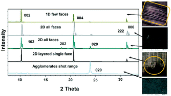
Lower concentrations between 1–3 mg ml−1 yielded form II, while 3–5 mg mL−1 resulted in form II in grey zone ends with form I dendrites. Fig. 3ii-a shows the BFDH morphology of form II showing the elongated π⋯π interaction along the b-axis and O–H⋯H hydrogen bonding interactions along the c-axis which results in prisms. Fig. 3ii-b shows a result of crystallization in EtOH as 1D growth and attachment energy calculations were carried out to understand the morphological importance of the faces, and the major faces were shown to be (002), (102), (200), (111) and (020), corresponding to attachment energies of −148.355, −157.486, −104.065, −126.878 and −116.607 kcal mol−1, respectively. Attachment energy calculations confirmed that the (002) face exhibits faster growth than the (200) face, so this major change in morphology was governed by the relative morphological importance of the (001) and (100) faces of form II at the edge interface of the substrate. Thompson et al. reported that structurally related additives, acetanilide and metacetamol, inhibited the growth of form I, however their experiments were not successful at producing the metastable form II.21 Here, APAP spherical shaped agglomerates were observed on the surface, which affect the growth at the edge and finally yield 2D growth of form II. Furthermore, edge-grown crystals (Fig. 3ii-c and d and S9 in the ESI†) confirmed that the (100) face was the major face whereas the (110), (101), (111), and (001) faces were the minor faces. Further experiments using form II block crystals as seeds were performed to reproduce the metastable phase in the absence of the SURMOF and these generated needles (Fig. 3ii-e and S7b and S9 in the ESI†) of form II. Therefore, in the presence of starting seeds that were of 2D block structure in the absence of the substrate, subsequent undirected growth of form II as 1D needles occurred, which might be due to the partial dissolution of seed block crystals of form II (produced by SURMOFs) during crystallization. This supports the importance of the designed SURMOF surface and all the crystal faces towards the substrate were analysed with Materials Studio (Fig. S10 in the ESI†). In both forms, the growth observed suggested that the OH faces outwards from APAP and binds with the MOF porous surface and directs crystal growth in another direction where weak interactions were possible with the lowest attachment energy faces as the predominated ones. SEM of the APAP crystals grown at different dilutions was performed to understand their morphology. Block and prism morphologies of form I were matched (Fig. 3iii-a and b and S11 in the ESI†) with face indexing experiments. Despite the formation of the blocks and prisms, at a medium dilution, dendrite growth of the form I (101) face was observed (Fig. 3iii-c and d) due to the mass transfer limitation and at low concentrations form II resulted in spherical agglomerates, and also 2D step growth (Fig. 3iii-e–g) was observed. Drop casting of 1 ml of a 1 mg/10 ml solution on the SURMOF surface yielded the spherical form II which further increased the population of spherical clusters, leading to 2D step growth with ledges, kinks, spherical adatoms and more steps (Fig. S11b16–20 in the ESI†) being observed. The image analysis of the edge (Fig. 3iii-g) also confirmed 2D growth of form II, which further confirmed SURMOF controlled growth. In order to confirm the orientation growth of form I and II bulk crystals, thin film XRD experiments were performed. Form I showed a selected 2θ at 13.96 of the (101) face, and form II at 10.3 of the (002) face, which further confirmed the homogeneity of the bulk crystals (Fig. S12c in the ESI†). A gradual decrease of the (002) face 2θ of form II was observed, which confirmed 2D growth and the agglomerates also showed a shot range 2θ (Fig. 4) which supports previous SEM analysis. A few batches provided similar results. Furthermore, spherical agglomerates and edge 2D crystals were identified as form II, analysed by XRD and double checked by Raman spectroscopy (Fig. S12e and S13 in the ESI†).
The presence of trace amounts of impurities and additives/imposters adsorb onto the crystal surfaces at the active site, acting as fences during crystal growth and cause substantial effects on the kinetics of the final crystal.2,26,27 The phenomena was further extended to the hetero surface, which is dimension controlled whereas the additives in solutions can adsorb in many directions onto various crystal faces. Here we proved that the MOF surface exhibited adsorption of the APAP nucleus during both nucleation and growth of crystalline APAP. QCM-D experiments supported the adsorption of APAP in solution, evidenced by a decreasing frequency due to loading of APAP. Adsorption of APAP to the HKUST-1 MOF pores due to the weak supramolecular interactions directed the nucleation and the growth of APAP form II, which is the most desired form of APAP. In addition, needle crystals are not suitable for formulations as they block filters during industrial processes. The resulting morphology in the present study will be an advantage to pharmaceutical engineering. MOF induced nucleation was investigated here for the first time and showed control over both morphology and polymorphism with a dual advantage and direct application to the drug required form. We believe that this new approach can hold significant implications to determine new/less stable forms through different growth mechanisms than conventional crystal growth.
GB and AM thank INDO-US for fellowship and Novartis for their financial support.
Conflicts of interest
The authors declare no conflict of interest.Notes and references
- A. J. Cruz-Cabeza and J. Bernstein, Chem. Rev., 2014, 114, 2170–2191 CrossRef CAS PubMed.
- M. Lahav and L. Leiserowitz, Phys. Scr., 2015, 90, 118003 CrossRef.
- J. C. Love, L. A. Estroff, J. K. Kriebel, R. G. Nuzzo and G. M. Whitesides, Chem. Rev., 2005, 105, 1103–1169 CrossRef CAS PubMed.
- X. Yang, B. Sarma and A. S. Myerson, Cryst. Growth Des., 2012, 12, 5521–5528 CAS.
- Y. Diao, T. Harada, A. S. Myerson, T. Alan Hatton and B. L. Trout, Nat. Mater., 2011, 10, 867–871 CrossRef CAS PubMed.
- M. Lang, A. L. Grzesiak and A. J. Matzger, J. Am. Chem. Soc., 2002, 124, 14834–14835 CrossRef CAS PubMed.
- Y. Diao, M. E. Helgeson, A. S. Myerson, T. A. Hatton, P. S. Doyle and B. L. Trout, J. Am. Chem. Soc., 2011, 133, 3756–3759 CrossRef CAS PubMed.
- J. A. Foster, M. O. M. Piepenbrock, G. O. Lloyd, N. Clarke, J. A. K. Howard and J. W. Steed, Nat. Chem., 2010, 2, 1037–1043 CrossRef CAS PubMed.
- R. I. Petrova, R. Patel and J. A. Swift, Cryst. Growth Des., 2006, 6, 2709–2715 CAS.
- J. Liu and C. Wöll, Chem. Soc. Rev., 2017, 46, 5730–5770 RSC.
- O. Shekhah, H. Wang, S. Kowarik, F. Schreiber, M. Paulus, M. Tolan, C. Sternemann, F. Evers, D. Zacher, R. A. Fischer and C. Wöll, J. Am. Chem. Soc., 2007, 129, 15118–15119 CrossRef CAS PubMed.
- S. Hermes, F. Schro, R. Chelmowski, C. Wöll and R. A. Fischer, J. Am. Chem. Soc., 2005, 127, 13744–13745 CrossRef CAS PubMed.
- H. Furukawa, K. E. Cordova, M. O'Keeffe and O. M. Yaghi, Science, 2013, 341, 1230444 CrossRef PubMed.
- J. Lee, J. Li and J. Jagiello, J. Solid State Chem., 2005, 178, 2527–2532 CrossRef CAS.
- O. Shekhah, J. Liu, R. A. Fischer and C. Wöll, Chem. Soc. Rev., 2011, 40, 1081 RSC.
- G. Nichols and C. S. Frampton, J. Pharm. Sci., 1998, 87, 684–693 CrossRef CAS PubMed.
- R. I. Ristic, S. Finnie, D. B. Sheen and J. N. Sherwood, J. Phys. Chem. B, 2001, 105, 9057–9066 CrossRef CAS.
- L. H. Thomas, C. Wales, L. Zhao and C. C. Wilson, Cryst. Growth Des., 2011, 11, 1450–1452 CAS.
- N. Tsapatsaris, B. A. Kolesov, J. Fischer, E. V. Boldyreva, L. Daemen, J. Eckert and H. N. Bordallo, Mol. Pharmaceutics, 2014, 11, 1032–1041 CrossRef CAS PubMed.
- T. K. Wijethunga, F. Baftizadeh, J. Stojakovic, A. S. Myerson and B. L. Trout, Cryst. Growth Des., 2017, 17, 3783–3795 CAS.
- C. Thompson, M. C. Davies, C. J. Roberts, S. J. B. Tendle and M. J. Wilkinson, Int. J. Pharm., 2004, 280, 137–150 CrossRef CAS PubMed.
- V. Stavila, J. Volponi, A. M. Katzenmeyer, M. C. Dixonb and M. D. Allendorf, Chem. Sci., 2012, 3, 1531–1540 RSC.
- F. Kirschhöfera, A. Riedera, C. Prechtl, B. Kühl, K. Sabljo, C. Wöll, U. Obst and G. Brenner-Weiß, Anal. Chim. Acta, 2013, 802, 95–102 CrossRef PubMed.
- P. Ganguly and G. R. Desiraju, CrystEngComm, 2010, 12, 817–833 RSC.
- M. C. Etter and J. C. Macdonald, Acta Crystallogr., Sect. B: Struct. Sci., 1990, 46, 256–262 CrossRef.
- E. Staab, L. Addadi, L. Leiserowitz and M. Lahav, Adv. Mater., 1990, 2, 40–43 CrossRef CAS.
- I. Weissbuch, M. Lahav and L. Leiserowitz, Cryst. Growth Des., 2003, 3, 125–150 CAS.
Footnote |
| † Electronic supplementary information (ESI) available: Experimental procedures and cif file CCDC no.: 1814819. For the ESI and crystallographic data in CIF or other electronic format see DOI: 10.1039/c8ce00272j |
| This journal is © The Royal Society of Chemistry 2018 |

