 Open Access Article
Creative Commons Attribution 3.0 Unported Licence
Covalently linking CuInS2 quantum dots with a Re catalyst by click reaction for photocatalytic CO2 reduction†
Jing
Huang
a,
Mélina Gilbert
Gatty
a,
Bo
Xu
a,
Palas Baran
Pati
a,
Ahmed S.
Etman
 b,
Lei
Tian
a,
Junliang
Sun
b,
Leif
Hammarström
a and
Haining
Tian
b,
Lei
Tian
a,
Junliang
Sun
b,
Leif
Hammarström
a and
Haining
Tian
 *a
*a
aDepartment of Chemistry-Ångström Laboratory, Uppsala University, Box 523, SE 751 20, Uppsala, Sweden. E-mail: haining.tian@kemi.uu.se
bDepartment of Materials and Environmental Chemistry (MMK), Stockholm University, SE 106 91 Stockholm, Sweden
First published on 10th July 2018
Abstract
Covalently linking photosensitizers and catalysts in an inorganic–organic hybrid photocatalytic system is beneficial for efficient electron transfer between these components. However, general and straightforward methods to covalently attach molecular catalysts on the surface of inorganic semiconductors are rare. In this work, a classic rhenium bipyridine complex (Re catalyst) has been successfully covalently linked to the low toxicity CuInS2 quantum dots (QDs) by click reaction for photocatalytic CO2 reduction. Covalent bonding between the CuInS2 QDs and the Re catalyst in the QD–Re hybrid system is confirmed by UV-visible absorption spectroscopy, Fourier-transform infrared spectroscopy and energy-dispersive X-ray measurements. Time-correlated single photon counting and ultrafast time-resolved infrared spectroscopy provide evidence for rapid photo-induced electron transfer from the QDs to the Re catalyst. Upon photo-excitation of the QDs, the singly reduced Re catalyst is formed within 300 fs. Notably, the amount of reduced Re in the linked hybrid system is more than that in a sample where the QDs and the Re catalyst are simply mixed, suggesting that the covalent linkage between the CuInS2 QDs and the Re catalyst indeed facilitates electron transfer from the QDs to the Re catalyst. Such an ultrafast electron transfer in the covalently linked CuInS2 QD–Re hybrid system leads to enhanced photocatalytic activity for CO2 reduction, as compared to the conventional mixture of the QDs and the Re catalyst.
Introduction
As a part of artificial photosynthesis, photocatalytic reduction of CO2 has gained substantial interest, since it is a green method to convert solar energy and the greenhouse gas CO2 into chemical feedstock.1–4 Until now, there were mainly three kinds of catalysts for CO2 photoreduction: semiconductors and metals,5–9 synthetic molecular catalysts10–14 and enzymes.15–18 Though enzymes display high turnover efficiency and good selectivity, the range of possible operative conditions is restricted, which greatly limits their large-scale use. Semiconductors and metals can photo-catalyze CO2 reduction with good stability and high activity;19,20 however, they always suffer from poor product selectivity.5–7,9 For example, a mixture of CO, CH4 and C2H6 was produced from CO2 by PbS nanoparticles loaded with a Cu co-catalyst.21 In contrast, synthetic molecular catalysts often exhibit excellent selectivity, for example photoreduction of CO2 by rhenium (Re) based catalysts normally produces only CO.22,23 However, inefficient absorption of visible light restrains their overall photocatalytic performance, and a combination with photosensitizers is usually needed to enhance their activity. There is numerous work to broaden the photoactive region of molecular catalysts by linking them with molecular photosensitizers, such as the synthesis of supramolecular photocatalysts with ruthenium (Ru) dyes as photosensitizers and Re or Ru complexes as catalysts bridged by different ligands,2,24–27 dyads with metalloporphyrins covalently tethered to rhenium complexes,28–30 and other systems with organic dyes coupled to molecular catalysts.31,32 However, molecular photosensitizer-based systems always suffer the problem of onerous synthetic routes.Colloidal quantum dots (QDs), a kind of semiconductor nanoparticle with size smaller than their exciton Bohr radius, can be a suitable alternative to molecular photosensitizers for building an inorganic–organic hybrid system for photocatalysis. Firstly, because of the quantum confinement effect, their bandgap can be easily tuned by their size, to optimize their absorption of solar light.33,34 Also, their band energy levels can be adjusted in a facile manner by varying the QD size,33,34 composition,35,36 and the capping ligand,37,38 to increase the driving force for electron transfer from QDs to catalysts. Secondly, due to the large surface-to-volume ratio of QDs, molecular catalysts could adsorb on the QD surface, and the charge transfer reaction becomes much faster than in a case with freely diffusing catalysts, in which the charge transfer is primarily mediated by bimolecular collision.39,40 Weiss et al. have recently employed CuInS2 QDs as photosensitizers for FeTPP41 and FeTMA catalysts,42 and achieved impressive photocatalytic activity for these hybrid systems, due to ultrafast electron transfer from QDs to catalysts. Thirdly, in addition to being photosensitizers, semiconductor nanoparticles can also work as electron reservoirs for the catalyst, which can slow down charge recombination in the system and prolong the lifetime of a catalyst intermediate.43 Last but not least, semiconductor nanoparticles can function as scaffolds for the catalysts, hindering the formation of catalyst dimers.44
To achieve efficient photo-induced catalysis, strong electronic coupling between QDs and catalysts is necessary to enable fast electron transfer from QDs to catalysts, and in that way, the catalyst molecules could be fed with more electrons to accomplish CO2 reduction. Numerous studies have shown that, compared to unbound photosensitizers and catalysts, hybrid systems consisting of covalently-bound sensitizers and catalysts always show stronger electronic coupling and more efficient electron transfer, resulting in higher activity and selectivity for CO2 reduction.45–47 Moreover, when molecular catalysts are linked with QDs to form a hybrid superstructure, the immobilization process on substrates is also simplified. On the other hand, without covalent bonds, the original ligand on the QDs can act as a barrier that inhibits the adsorption of catalysts on the QD surface, hence, hindering electron transfer between them.45 To date, only a few methods of covalent attachment of catalysts onto the QD surface have been reported, and most of them are based on molecular catalysts with an anchoring group, such as thiol groups45 or phosphonate groups,47,48 which can bind the catalyst molecules as ligands to the QD surface. However, the synthesis and purification processes of such catalysts with thiol or phosphate groups are often arduous. Hence, a synthetically simpler and more tunable approach for immobilizing catalysts on the QD surface is highly desirable.
The “click” reaction with azide–alkyne cycloaddition is an ideal reaction for covalent linkage of two molecules owing to its high selectivity, high yield and fast reaction kinetics under mild reaction conditions.49–52 It is also suitable for covalently linking organic molecules to conductive surfaces.53,54 In this work, we covalently linked the catalyst Re(4-azidomethyl-4′-methyl-2,2′-bipyridine)(CO)3Cl (Re catalyst) with CuInS2 QDs by a copper-free click reaction, to synthesize the QD–Re hybrid system for CO2 photoreduction. This is the first time that a molecular catalyst was attached on QDs with covalent bonds through a copper-free click reaction for photocatalytic reactions. Each reaction component was easy to prepare, which can be a demonstration for a straightforward and versatile strategy to link molecular catalysts with inorganic semiconductor nanoparticles. We also provide evidence that the photocatalytic activity of these QD–Re hybrid systems was enhanced by efficient electron transfer between the QDs and the Re catalyst due to the covalent linkage.
Experimental section
Materials
Indium acetate (In(OAc)3, 99.99%), copper iodide (CuI, ≥99.5%), oleylamine (OAm, 97%), 1-octadecene (ODE, 90%), 3-mercaptopropionic acid (3-MPA, >99%), sulfur powder (S, 99.5%), N-(3-dimethylaminopropyl)-N′-ethylcarbodiimide hydrochloride (EDC, ≥99.0%), N-hydroxysuccinimide (NHS, 98%), dibenzocyclooctyne-amine (DBCO-amine), triethanolamine (TEOA, ≥99.0%), and dimethyl sulfoxide (DMSO) were purchased from Sigma-Aldrich. All chemicals and solvents were used as received.Synthesis and ligand exchange of CuInS2 QDs
The synthesis of CuInS2 QDs was based on a reported method with minor modifications.55 Briefly, 29 mg of In(OAc)3 and 5 mg of CuI were put into a flask which contained 4 mL of ODE and 2 mL of OAm, and then the solution was purged with argon, followed by heating to 180 °C. Then 0.4 mL of sulfur precursor solution, prepared by dissolving 32 mg of sulfur powder in 1 mL of OAm, was injected into the flask, and the reaction system was kept at 180 °C for 20 min before the heater was removed. The obtained CuInS2 QDs were purified by dispersing in hexane and precipitating with ethanol, and the final QDs were dispersed in 10 mL of toluene to form the CuInS2 QD stock solution.Then the original ligands on QDs were exchanged with 3-MPA through a ligand exchange reaction. Specifically, a MPA ligand solution, prepared by mixing 0.3 mL of MPA with 0.7 mL of methanol, with the pH of the solution adjusted to 10 using 38% NaOH aqueous solution, was dropped into 5 mL of CuInS2 QD stock solution under strong stirring. After stirring for 40 minutes at room temperature, MPA capped QDs, which were in the lower part, were collected and purified with water and acetone, and finally dispersed in 10 mL of DMSO.
The Re catalyst was synthesized by following a reported method.31
Preparation of the QD–Re hybrid system
Typically, 5 mL of QD–DMSO solution, together with 5 mg of EDC and 2.9 mg of NHS dissolved in 1.5 mL of DMSO, were loaded in the flask, and then purged with argon for 15 min under stirring. The linker solution, produced by dissolving 10 mg of DBCO-amine in 1 mL of DMSO, was injected into the flask. Subsequently, 15 mg of the Re catalyst dissolving in 1 mL of DMSO was injected into the reaction system at room temperature. After stirring for 4.5 h, the reaction was stopped, and the covalently linked QD–Re hybrid system was obtained from centrifugation of the reaction solution. Finally, the QD–Re hybrid system was dispersed in 10 ml of DMSO, forming a clear brown-yellowish solution.CO2 photocatalytic reduction
A 2 mL solution of the prepared sample (0.3 mM), TEOA (0.1 M) and DMSO was loaded into a 4.5 mL cuvette, and purged with Ar and CO2 for 30 min and 25 min respectively. The sealed cuvette was then irradiated with a LED white lamp (≥420 nm, comparable light intensity to 1 sunlight in the region between 420 nm and 750 nm), for different times under stirring. The produced CO was taken out using a gas-tight syringe from the headspace, and measured by gas chromatography (GC).Characterization
Ground-state ultraviolet-visible (UV-vis) absorption spectra were recorded on a Varian Cary 5000. The ground-state UV-vis spectrum of CuInS2 QDs was obtained in aqueous solution, while the UV-vis spectra of the CuInS2 QD–Re hybrid system and the Re catalyst alone were obtained in DMSO. Fluorescence spectra were obtained on a Horiba Jobin Yvon Fluorolog with an excitation wavelength of 470 nm. The setup for time-correlated single photon counting (TCSPC) measurements was the same as in our previous work,50 with a light source of 470.4 nm and a long-pass filter to screen the photons below 640 nm. All samples were loaded in 1 cm cuvettes with DMSO as the solvent and purged with Ar prior to measurements. Fourier-transform infrared (FTIR) spectra were collected from solid pellets, prepared by mixing the sample powder with KBr, by using a Bruker IFS 66v/S FTIR spectrophotometer. GC measurements were conducted on an Agilent Technologies 490 Micro GC with Ar carrier gas, and COX columns were used. Calibration curves for CO were established by injecting a known amount of CO. The morphology and elemental analysis of the QD samples were explored by transmission electron microscopy (TEM, JEOL JEM-2100F) equipped with an energy dispersive X-ray (EDX) detector using an accelerating voltage of 200 kV.Femtosecond mid-infrared transient absorption spectroscopy
The 800 nm output of a Ti:sapphire based amplifier with integrated oscillator and pump lasers (800 nm, 40 fs, 3 kHz, Libra LHE, Coherent Inc.) was split into two beams which were used to pump two TOPAS Primes coupled with frequency mixers (Light Conversion Ltd). This generates the visible pump at 520 nm and a broad mid-IR probe spectrum (2210–1825 cm−1). The pump pulse energy hitting the sample was adjusted using a neutral density filter placed before the sample and was varied between 66 nJ and 830 nJ at 520 nm (spot size ca. 1900 μm2). For the probe, the probe beam was split into two probe and reference beams. Detection of the probe and reference beams was done using a femtosecond transient absorption spectrometer (Helios IR, Ultrafast Systems LLC). The instrument response function for these experiments is ca. 300 fs. All spectra were recorded in a sealed liquid cell (Specac) consisting of two CaF2 windows separated by a PTFE spacer of 640 μm path length. During the measurements, the samples were moved manually to minimize possible laser-induced sample damage. The solvent was DMSO in all experiments.Results and discussion
Synthesis of the QD–Re hybrid system
In this work, the covalent linkage in the QD–Re hybrid system was realized from a copper-free click reaction between the alkyne group in the linker molecule (dibenzocyclooctyne-amine, DBCO-amine) and the azide group in the Re catalyst, as shown in Fig. 1. The mercaptopropionic acid (MPA) capped CuInS2 QDs (tetragonal chalcopyrite structure, Fig. S1†), synthesized by following a literature method,55 were firstly coupled with the linker DBCO-amine by amidation reaction through N-(3-dimethylaminopropyl)-N′-ethylcarbodiimide hydrochloride (EDC)/N-hydroxysuccinimide (NHS) in DMSO. Subsequently, the Re catalyst functionalized with an azide group, which can quickly bind to the linker molecules on the surface of CuInS2 QDs through click reaction, was added to the reaction system, by forming the CuInS2 QD–Re hybrid system. All of these reactions were performed at room temperature and processed in solution, which is therefore convenient for scaling up. Before binding with the linker molecules, the MPA capped CuInS2 QDs showed poor dispersibility in the organic solvent DMSO. However, after coupling with the linker and Re catalyst molecules, the DMSO solution of the CuInS2 QD–Re hybrid system became much clearer, as illustrated by the insert photograph in Fig. 1. TEM images (Fig. S2†) show that, compared to MPA capped CuInS2 QDs, there is no obvious change in size (7 ± 1 nm) or shape (triangle) of the CuInS2 QDs after binding with the Re catalyst that could explain a better dispersibility. Thus, the improved dispersibility of the QDs in DMSO points towards a successful binding of the catalyst to the surface of the CuInS2 QDs, which can increase the hydrophobicity of the QDs.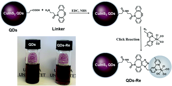 | ||
| Fig. 1 Synthetic routes of the covalently-linked CuInS2 QD–Re hybrid system. Insert: Photograph of CuInS2 QDs and the CuInS2 QD–Re hybrid system dispersed in DMSO. | ||
Fig. 2 shows the UV-Vis ground-state absorption spectra of the CuInS2 QDs, the CuInS2 QD–Re hybrid system, and the Re catalysts. The as-synthesized CuInS2 QDs exhibited a broad excitonic peak centered at around 540 nm with a long tail extended to 800 nm (detailed in Fig. S3†), which illustrates the fact that the CuInS2 QDs can absorb the entire range of visible light up to near infrared light. The absorption of the Re catalyst began from 500 nm, and featured a maximum absorption at around 375 nm. Upon covalent binding of the Re catalyst onto the surface of CuInS2 QDs, the CuInS2 QD–Re hybrid system displayed absorption features both from the CuInS2 QDs and the Re catalyst. The difference spectrum (the absorption spectrum of CuInS2 QD–Re subtracted from that of CuInS2 QDs, green dotted line in Fig. 2) resembled the absorption spectrum of the pure linker-Re catalyst, and the latter was prepared similarly to the CuInS2 QD–Re hybrid system, but without CuInS2 QDs in the reaction system (see in Fig. S4†). Both of them showed a slight bathochromic shift from that of the pure Re catalyst, probably due to the weaker electron withdrawing ability of the ligand. The absorption spectra confirmed the presence of the Re catalyst attached onto the CuInS2 QD surface in the CuInS2 QD–Re hybrid system, and the loading efficiency of catalyst molecules was about 41% (mole of the Re catalyst on per mole of CuInS2 QDs) as estimated from the increase in absorbance at 375 nm compared to that of the neat QD sample.
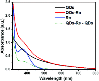 | ||
| Fig. 2 UV-Vis absorption spectra of CuInS2 QDs in aqueous solution, the CuInS2 QD–Re hybrid system and the Re catalyst in DMSO. | ||
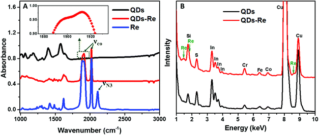
To further confirm that the Re catalyst was attached on the QDs, Fourier-transform infrared spectroscopy (FTIR) measurements were conducted and the results are presented in Fig. 3A. The FTIR spectrum of the Re catalyst displayed three characteristic absorption peaks due to carbonyl stretches at νco = 1898, 1912 and 2021 cm−1, which was in agreement with previous reports on similar Re(bpy)(CO)3L complexes.44,56 Additionally, introduction of the azide group in the Re catalyst structure (Fig. 1) produced another absorption peak νN3 at 2110 cm−1. For the CuInS2 QD–Re hybrid system, the νco stretches were preserved, while the azide group stretch vanished due to the click reaction between the linker molecule and the catalyst molecule. In comparison, there were only weak νco stretch bands for the control sample prepared without a linker molecule (Fig. S5,† sample labeled as QDsRe), implying that the Re catalysts can adsorb on the surface of QDs only to a slight extent in the absence of linker molecules. Furthermore, Re signals were detected from the CuInS2 QD–Re hybrid system by energy-dispersive X-ray (EDX) measurements, as shown in Fig. 3B. Therefore, by combining the above results, we conclude that our CuInS2 QD–Re hybrid system was formed through the linker assisted click reaction.
Electron transfer in the covalently-linked QD–Re hybrid system
Due to the covalent bond in the CuInS2 QD–Re hybrid system, the electronic coupling between QDs and the Re catalyst is expected to be strengthened, and therefore photoinduced electron transfer (ET) from the excited QDs to the Re catalyst may occur in the hybrid system. Steady-state fluorescence spectra were first recorded for the CuInS2 QDs with and without linked Re catalyst molecules, as well as the mixture solution of the CuInS2 QDs and the Re catalyst (i.e. without a covalent bond between them) for comparison. As shown in Fig. S6,† upon excitation with 470 nm, the CuInS2 QDs exhibited fluorescence around 750 nm, and the Re catalyst alone exhibited strong photoluminescence (PL) around 630 nm. After binding with the Re catalyst, the PL emission of the CuInS2 QDs was almost completely quenched, while the fluorescence of the Re catalyst was retained. The retained fluorescence of Re should originate from direct excitation of a non-reduced Re catalyst. Considering that energy transfer from the QDs to the Re catalyst was energetically unfavorable (no overlap between the emission of the QDs and the absorption of the Re catalyst), the PL quenching can only be induced by charge transfer from the QDs to the linker or the Re catalyst. However, the linker alone only reduced the PL intensity to a small extent (Fig. S7†). Differential pulse voltammetry (DPV) measurement of the CuInS2 QDs and cyclic voltammetry (CV) measurement of the Re catalyst (Fig. S8†) showed that their first reduction potentials were −0.99 and −0.93 V vs. SCE, respectively, implying that electron transfer from the QDs to the Re catalyst was energetically possible. The PL intensity of the CuInS2 QDs in the mixed sample of CuInS2 QDs and Re catalyst only partially decreased (Fig. S6†), as compared to the as-synthesized CuInS2 QDs, which further indicated that covalent binding in the CuInS2 QD–Re hybrid system enhanced the quenching of the CuInS2 QD emission.Time-correlated single photon counting (TCSPC) measurements of the CuInS2 QD–Re hybrid system confirmed the accelerated decay of the fluorescence of the QDs in the presence of the Re catalyst. From the data presented in Fig. 4 and the results from biexponential fits in Table 1, we can see that the PL lifetime of QDs in the mixed solution partially decreased from that of the as-synthesized CuInS2 QDs, and the decrease was mainly in the fast decay component (τ1 = 0.587 ns (77.3%) for the mixed sample, and τ1 = 2.39 ns (62.8%) for the as-synthesized CuInS2 QDs), which was consistent with the results from steady-state fluorescence measurements. In contrast, the PL lifetime of the CuInS2 QD–Re hybrid system dramatically decreased, with τ1 = 0.243 ns (98.8%), τ2 = 19.7 ns (1.2%), indicating that almost all the fluorescence decayed within 1 ns. The short PL lifetime of the CuInS2 QD–Re hybrid system confirmed that the fluorescence of the CuInS2 QDs was quenched by the covalently bound Re catalyst, and the high PL quenching yield suggested that the ET process in the system was efficient. With the average PL lifetime defined as 〈τ〉 = A1τ1 + A2τ2, where A1 and A2 are the amplitude fractions, the average lifetime for ET can be calculated according to eqn (1). The efficiency of ET is then given by eqn (2), where the latter term is equal to the ratio of the areas under the respective PL decay curve.
 | (1) |
 | (2) |
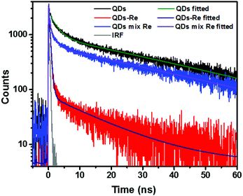 | ||
| Fig. 4 Decays of the photoluminescence of CuInS2 QDs, CuInS2 QD–Re hybrid system, and the mixture solution of CuInS2 QDs and the Re catalyst, monitored at the emission wavelengths above 640 nm, after excitation at 470 nm in DMSO. The lifetimes obtained from the fitting procedure are listed in Table 1. | ||
| Sample | QDs | QD–Re | QD–Re mixture |
|---|---|---|---|
| a Some deviations from a perfect fit (see χ2/Nd values, and residual plots in Fig. S9) indicated that the interfacial kinetics was somewhat more heterogeneous than that described by the fit. For the purpose of the present analysis, however, a biexponential fit was still sufficient to demonstrate the large differences between the samples. | |||
| τ 1 (ns) | 2.39 (62.8%) | 0.243 (98.8%) | 0.587 (77.3%) |
| τ 2 (ns) | 36.7 (37.2%) | 19.7 (1.2%) | 29.9 (22.7%) |
| Weighted average PL lifetime <τ> (ns) | 15 | 0.48 | 7.2 |
| χ 2/Nd | 1.54 | 1.70 | 1.52 |
According to eqn (1) and (2), and assuming that all PL quenching arose from electron transfer, the average ET lifetime (〈τET〉) and efficiency (ηET) of 0.49 ns and 97% were obtained for the QD–Re hybrid system. In other words, the majority of the electron transfer processes from CuInS2 QDs to the Re catalyst occurred within 1 ns. This efficient ET process is presumably because of a strengthened electronic coupling between the CuInS2 QDs and the Re catalyst, through forming the QD–Re covalent bond.39 Note that any process faster than ca. 30 ps cannot be resolved by the TCSPC experiment.
In order to further investigate the origin of the PL quenching, transient absorption spectroscopy measurements in the mid-IR region were performed. The reduced rhenium should give a clear signature in the infrared region due to strong νco stretches according to the literature.28,57–59 Fig. S10† and Fig. 5A show the time-resolved IR (TRIR) spectra of the CuInS2 QD–Re hybrid system under 520 nm excitation after subtraction of the background absorption of the conduction band electrons in the QDs. The spectra show bleaches of the ground-state CO bands of the Re catalyst at 2030, 1924, and 1897 cm−1, which were slightly blue-shifted as compared to the FTIR spectrum of the QD–Re hybrid system. This blue-shift may be due to the solvent effect since the TRIR spectra were recorded in solution, while the FTIR spectra were recorded in solid samples.44 Simultaneously, the appearance of a positive band at 2012 cm−1 could be observed, which is red-shifted by 18 cm−1 from the ground state of the CO stretching band at 2030 cm−1. Numerous studies have shown that the νco stretch bands of the one-electron-reduced species [Re(bpy)(CO)3Cl]− normally shift to a lower energy by around 20 cm−1 from that of the ground state.28,32,40,57–62 Therefore, the positive band at 2012 cm−1 could be assigned to the reduced form of the Re catalyst. Similar TRIR features were also observed in CdSe QD–Re(CO)3Cl(dcbpy) complexes,40 and these results suggested that the photoinduced electrons in conduction band of QDs could effectively transfer to the Re catalyst, generating the Re catalyst anion:
| QDs* + Re → QDs+ + Re−. |
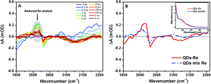 | ||
| Fig. 5 (A) fs-TRIR spectra for the CuInS2 QD–Re hybrid system under 520 nm excitation and (B) comparison of the fs-TRIR spectra at 1 ps for the CuInS2 QD–Re hybrid system and the mixed sample of CuInS2 QDs and Re catalysts. Inset: UV-Vis absorption spectra of solutions of the CuInS2 QD–Re hybrid system and the mixed sample of CuInS2 QDs and Re catalysts used in the fs-TRIR measurements. For the fs-TRIR spectra, the background absorption of the conduction band electrons of the QDs has been subtracted to emphasize the molecular signature of the Re catalyst. The raw data (i.e. before background subtraction) can be found in the ESI in Fig. S13.† The region below 1950 cm−1 is not shown because of the overlapping TRIR signals of the samples with absorption of the solvent (DMSO). | ||
From Fig. 5A, we can find that the feature of the Re catalyst anion can be observed already at 300 fs after excitation, which means the electron transfer from the QDs to the Re catalyst must occur within less than 300 fs. The transient IR spectra of the Re catalyst alone recorded under the same conditions show negligible features of the Re excited state and singly reduced Re, which excludes direct excitation of the catalyst at 520 nm (Fig. S11†). Unsurprisingly, the reduced Re catalyst was also detected from the mixed sample of CuInS2 QDs and Re catalyst (Fig. S12†). However, the amount of catalyst anions was less than the ones in the CuInS2 QD–Re hybrid system. As shown by Fig. 5B, the signal of the reduced Re catalyst was larger in the CuInS2 QD–Re hybrid system though the amount of the Re catalyst was slightly higher in the mixed sample (see the inserted comparison spectra in Fig. 5B). These results suggested that the ET process was more efficient in the covalently linked hybrid system that in the simple mixture. The signals from the reduced Re catalyst decayed with an average lifetime of ≥1.1 ns, with a significant component >5 ns (see Fig. S14 and Table S1†). Thus, the slower ET components indicated by TCSPC will not lead to an obvious rise of the reduced Re catalyst IR signal, as formation occurs concomitant with (or is slower than) its subsequent decay.
Photocatalytic activity and mechanism
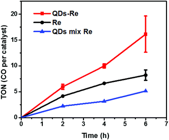
The photocatalytic activity towards CO2 reduction of our CuInS2 QD–Re hybrid system was evaluated, in the presence of TEOA as an electron donor (Fig. 6). The turnover number (TON), which is defined as the number of moles of CO that a mole of catalyst converts, was employed as the evaluation parameter for all samples. Control experiments conducted without either Re catalyst, TEOA, CO2 or light, did not produce any significant amounts of CO, confirming that all these components play active roles in CO2 reduction.Because a LED white light (≥420 nm) was used as the light source, the Re catalyst alone exhibited moderate photocatalytic activity toward CO2 reduction, with a TON of 8 after 6 h. No H2 was generated from the photocatalytic system (see GC traces in Fig. S15†), which is similar to other reports.44 When the Re catalyst was attached on the surface of the QDs in the CuInS2 QD–Re hybrid system, the TON of CO by the catalyst was significantly enhanced to 16 after 6 h of photocatalysis. In contrast, in the mixed solution of QDs and Re catalyst, the QDs inhibited the activity of the catalyst, presumably by parasitic light absorption, resulting in a lower TON of 5. These results demonstrated that the linkage between QDs and the catalyst was important for the improvement of the photocatalytic activity of the catalyst, which could contribute to efficient ET from the QDs to the catalyst and then benefit the electron accumulation of the catalyst for photocatalytic CO2 reduction. The lower TON for the mixed system compared to the Re catalyst alone can be explained by the strong visible light absorption of CuInS2 QDs, which competes with the light absorption of the Re catalyst.
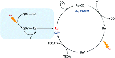
Based on the previous studies by Ishitani and other groups,14,63,64 we proposed a photocatalytic mechanism of the CuInS2 QD–Re hybrid system for CO2 reduction. Without QDs, a bare Re catalyst is a classic catalyst for CO2 reduction with high selectivity, and the photocatalytic mechanism is well studied.14,44,65,66 As shown in Scheme 1, after absorbing light with a wavelength shorter than 500 nm, the Re catalyst can be excited, and then the excited catalyst Re* will quickly acquire an electron from the electron donor TEOA, generating one-electron reduced (OER) species of the Re complex. Notably, unlike the electro-catalysis of CO2 reduction by the Re catalyst (Fig. S8b†),56 the photo-induced process is conducted by the OER species of the Re complexes. The OER species play two significant roles in photocatalytic CO2 reduction: firstly, they can bind with CO2 in solution after ligand elimination, forming a [CO2 adduct]; secondly, a neighboring OER species can also feed electrons to the [CO2 adduct], converting CO2 to CO.14,63 When CuInS2 QDs were bound to the Re catalyst, forming the CuInS2 QD–Re hybrid system, the CuInS2 QDs can utilize the solar light with longer wavelengths to generate electron–hole pairs. Then the photoinduced electrons in the QDs can transfer to the Re catalyst, contributing to more OER species, as proved by the TRIR results, and the QDs can subsequently be regenerated by TEOA. In the QD–Re hybrid system, the average lifetime of OER, i.e. the reduced Re catalyst, was ≥1.1 ns (τ1 = 20.4 ps (54%), τ2 = 994 ps (31%), τ3 > 5 ns (15%), Fig. S12 and Table S1†), which is long enough to feed electrons to the [CO2 adduct] and reduce CO2. Compared to an unsensitized Re catalyst, there is an additional channel for the formation of OER species in the CuInS2 QD–Re hybrid system; therefore, the photocatalytic activity of the CuInS2 QD–Re hybrid system was improved.
Conclusions
In summary, the Re catalyst was successfully linked to CuInS2 QDs by covalent bonds formed via a copper-free click reaction. The formation of the linked system has been confirmed by UV-Vis, FTIR and EDX measurements. The electron transfer studies have been carried out by steady-state and time-resolved fluorescence spectroscopy methods, and femto-second transient absorption in the mid-IR region. From this study, we concluded that a fast electron transfer from the QDs to the Re catalyst occurred in the CuInS2 QD–Re hybrid system, which stimulated the generation of reduced Re species, and thus improved the photocatalytic performance of the Re catalyst.After full optimization of the hybrid system, we aim to immobilize the QD–Re system on NiO electrodes to fabricate a photocathode for CO2 reduction.
Conflicts of interest
The authors declare no competing financial interest.Acknowledgements
This work was supported by the Göran Gustafsson Foundation, the Olle Engkvist Byggmästare Foundation, the Swedish Research Council and the Swedish Energy Agency. Lei Tian also thanks the support from the China Scholarship Council. We extend our special thanks to Jens Föhlinger (Uppsala University) for his kind help in calculating the lifetime of the reduced Re catalyst and many helpful comments to this work. Many thanks go to Rui Sun (Uppsala University) for her great help in XRD measurement. We also thank Dr Nicolas Queyriaux, Ben Johnson, and Professor Sascha Ott (Uppsala University) for their kind help and support in GC measurements. Great gratitude also goes to Prof. Xinhua Zhong and Zhenxiao Pan (South China Agricultural University,) for their valuable advice on the synthesis of CuInS2 QDs.References
- X. Chang, T. Wang and J. Gong, Energy Environ. Sci., 2016, 9, 2177–2196 RSC.
- G. Sahara and O. Ishitani, Inorg. Chem., 2015, 54, 5096–5104 CrossRef PubMed.
- W.-H. Wang, Y. Himeda, J. T. Muckerman, G. F. Manbeck and E. Fujita, Chem. Rev., 2015, 115, 12936–12973 CrossRef PubMed.
- J. L. White, M. F. Baruch, J. E. Pander, Y. Hu, I. C. Fortmeyer, J. E. Park, T. Zhang, K. Liao, J. Gu, Y. Yan, T. W. Shaw, E. Abelev and A. B. Bocarsly, Chem. Rev., 2015, 115, 12888–12935 CrossRef PubMed.
- S. Wang, B. Y. Guan, Y. Lu and X. W. D. Lou, J. Am. Chem. Soc., 2017, 139, 17305–17308 CrossRef PubMed.
- B. Aurian-Blajeni, M. Halmann and J. Manassen, Sol. Energy, 1980, 25, 165–170 CrossRef.
- S. C. Roy, O. K. Varghese, M. Paulose and C. A. Grimes, ACS Nano, 2010, 4, 1259–1278 CrossRef PubMed.
- X. Jiao, Z. Chen, X. Li, Y. Sun, S. Gao, W. Yan, C. Wang, Q. Zhang, Y. Lin, Y. Luo and Y. Xie, J. Am. Chem. Soc., 2017, 139, 7586–7594 CrossRef PubMed.
- K. P. Kuhl, T. Hatsukade, E. R. Cave, D. N. Abram, J. Kibsgaard and T. F. Jaramillo, J. Am. Chem. Soc., 2014, 136, 14107–14113 CrossRef PubMed.
- C. Costentin, S. Drouet, M. Robert and J.-M. Savéant, Science, 2012, 338, 90–94 CrossRef PubMed.
- J. Bonin, M. Robert and M. Routier, J. Am. Chem. Soc., 2014, 136, 16768–16771 CrossRef PubMed.
- J. D. Froehlich and C. P. Kubiak, J. Am. Chem. Soc., 2015, 137, 3565–3573 CrossRef PubMed.
- H. Takeda, C. Cometto, O. Ishitani and M. Robert, ACS Catal., 2017, 7, 70–88 CrossRef.
- H. Takeda, K. Koike, H. Inoue and O. Ishitani, J. Am. Chem. Soc., 2008, 130, 2023–2031 CrossRef PubMed.
- B. A. Parkinson and P. F. Weaver, Nature, 1984, 309, 148–149 CrossRef.
- Y. S. Chaudhary, T. W. Woolerton, C. S. Allen, J. H. Warner, E. Pierce, S. W. Ragsdale and F. A. Armstrong, Chem. Commun., 2012, 48, 58–60 RSC.
- J. Shi, Y. Jiang, Z. Jiang, X. Wang, X. Wang, S. Zhang, P. Han and C. Yang, Chem. Soc. Rev., 2015, 44, 5981–6000 RSC.
- T. Wagner, U. Ermler and S. Shima, Science, 2016, 354, 114–117 CrossRef PubMed.
- Ş. Neaţu, J. A. Maciá-Agulló, P. Concepción and H. Garcia, J. Am. Chem. Soc., 2014, 136, 15969–15976 CrossRef PubMed.
- M. Tahir and N. S. Amin, Appl. Catal., B, 2015, 162, 98–109 CrossRef.
- C. Wang, R. L. Thompson, P. Ohodnicki, J. Baltrus and C. Matranga, J. Mater. Chem., 2011, 21, 13452–13457 RSC.
- J. Hawecker, J.-M. Lehn and R. Ziessel, J. Chem. Soc., Chem. Commun., 1983, 536–538 RSC.
- T. Nakajima, Y. Tamaki, K. Ueno, E. Kato, T. Nishikawa, K. Ohkubo, Y. Yamazaki, T. Morimoto and O. Ishitani, J. Am. Chem. Soc., 2016, 138, 13818–13821 CrossRef PubMed.
- Y. Tamaki, K. Koike, T. Morimoto and O. Ishitani, J. Catal., 2013, 304, 22–28 CrossRef.
- Y. Tamaki, T. Morimoto, K. Koike and O. Ishitani, Proc. Natl. Acad. Sci. U. S. A., 2012, 109, 15673–15678 CrossRef PubMed.
- K. Sekizawa, K. Maeda, K. Domen, K. Koike and O. Ishitani, J. Am. Chem. Soc., 2013, 135, 4596–4599 CrossRef PubMed.
- Y. Kou, S. Nakatani, G. Sunagawa, Y. Tachikawa, D. Masui, T. Shimada, S. Takagi, D. A. Tryk, Y. Nabetani, H. Tachibana and H. Inoue, J. Catal., 2014, 310, 57–66 CrossRef.
- C. D. Windle, M. W. George, R. N. Perutz, P. A. Summers, X. Z. Sun and A. C. Whitwood, Chem. Sci., 2015, 6, 6847–6864 RSC.
- J. Schneider, K. Q. Vuong, J. A. Calladine, X.-Z. Sun, A. C. Whitwood, M. W. George and R. N. Perutz, Inorg. Chem., 2011, 50, 11877–11889 CrossRef PubMed.
- K. Kiyosawa, N. Shiraishi, T. Shimada, D. Masui, H. Tachibana, S. Takagi, O. Ishitani, D. A. Tryk and H. Inoue, J. Phys. Chem. C, 2009, 113, 11667–11673 CrossRef.
- G. A. Andrade, A. J. Pistner, G. P. A. Yap, D. A. Lutterman and J. Rosenthal, ACS Catal., 2013, 3, 1685–1692 CrossRef PubMed.
- J. F. Martinez, N. T. La Porte and M. R. Wasielewski, J. Phys. Chem. C, 2018, 122, 2608–2617 CrossRef.
- L. Brus, J. Phys. Chem., 1986, 90, 2555–2560 CrossRef.
- W. W. Yu, L. Qu, W. Guo and X. Peng, Chem. Mater., 2003, 15, 2854–2860 CrossRef.
- X. Zhong, M. Han, Z. Dong, T. J. White and W. Knoll, J. Am. Chem. Soc., 2003, 125, 8589–8594 CrossRef PubMed.
- M. D. Regulacio and M.-Y. Han, Acc. Chem. Res., 2010, 43, 621–630 CrossRef PubMed.
- K. E. Roelofs, T. P. Brennan and S. F. Bent, J. Phys. Chem. Lett., 2014, 5, 348–360 CrossRef PubMed.
- P. K. Santra, A. F. Palmstrom, J. T. Tanskanen, N. Yang and S. F. Bent, J. Phys. Chem. C, 2015, 119, 2996–3005 CrossRef.
- K. E. Knowles, M. Malicki and E. A. Weiss, J. Am. Chem. Soc., 2012, 134, 12470–12473 CrossRef PubMed.
- J. Huang, D. Stockwell, Z. Huang, D. L. Mohler and T. Lian, J. Am. Chem. Soc., 2008, 130, 5632–5633 CrossRef PubMed.
- S. Lian, M. S. Kodaimati, D. S. Dolzhnikov, R. Calzada and E. A. Weiss, J. Am. Chem. Soc., 2017, 139, 8931–8938 CrossRef PubMed.
- S. Lian, M. S. Kodaimati and E. A. Weiss, ACS Nano, 2018, 12, 568–575 CrossRef PubMed.
- M. Abdellah, A. M. El-Zohry, L. J. Antila, C. D. Windle, E. Reisner and L. Hammarström, J. Am. Chem. Soc., 2017, 139, 1226–1232 CrossRef PubMed.
- C. D. Windle, E. Pastor, A. Reynal, A. C. Whitwood, Y. Vaynzof, J. R. Durrant, R. N. Perutz and E. Reisner, Chem. – Eur. J., 2015, 21, 3746–3754 CrossRef PubMed.
- M. F. Kuehnel, K. L. Orchard, K. E. Dalle and E. Reisner, J. Am. Chem. Soc., 2017, 139, 7217–7223 CrossRef PubMed.
- S. Sato, T. Morikawa, S. Saeki, T. Kajino and T. Motohiro, Angew. Chem., Int. Ed., 2010, 49, 5101–5105 CrossRef PubMed.
- K. Muraoka, H. Kumagai, M. Eguchi, O. Ishitani and K. Maeda, Chem. Commun., 2016, 52, 7886–7889 RSC.
- E.-G. Ha, J.-A. Chang, S.-M. Byun, C. Pac, D.-M. Jang, J. Park and S. O. Kang, Chem. Commun., 2014, 50, 4462–4464 RSC.
- J. C. Jewett and C. R. Bertozzi, Chem. Soc. Rev., 2010, 39, 1272–1279 RSC.
- P. B. Pati, L. Zhang, B. Philippe, R. Fernández-Terán, S. Ahmadi, L. Tian, H. Rensmo, L. Hammarström and H. Tian, ChemSusChem, 2017, 10, 2480–2495 CrossRef PubMed.
- N. Kaeffer, J. Massin, C. Lebrun, O. Renault, M. Chavarot-Kerlidou and V. Artero, J. Am. Chem. Soc., 2016, 138, 12308–12311 CrossRef PubMed.
- E. S. Andreiadis, P.-A. Jacques, P. D. Tran, A. Leyris, M. Chavarot-Kerlidou, B. Jousselme, M. Matheron, J. Pécaut, S. Palacin, M. Fontecave and V. Artero, Nat. Chem., 2013, 5, 48–53 CrossRef PubMed.
- S. A. Yao, R. E. Ruther, L. Zhang, R. A. Franking, R. J. Hamers and J. F. Berry, J. Am. Chem. Soc., 2012, 134, 15632–15635 CrossRef PubMed.
- Y. Chen, H. Chen and H. Tian, Chem. Commun., 2015, 51, 11508–11511 RSC.
- Z. Pan, I. Mora-Seró, Q. Shen, H. Zhang, Y. Li, K. Zhao, J. Wang, X. Zhong and J. Bisquert, J. Am. Chem. Soc., 2014, 136, 9203–9210 CrossRef PubMed.
- M. D. Sampson, J. D. Froehlich, J. M. Smieja, E. E. Benson, I. D. Sharp and C. P. Kubiak, Energy Environ. Sci., 2013, 6, 3748–3755 RSC.
- J. M. Smieja and C. P. Kubiak, Inorg. Chem., 2010, 49, 9283–9289 CrossRef PubMed.
- A. Gabrielsson, F. Hartl, H. Zhang, J. R. Lindsay Smith, M. Towrie, A. Vlček and R. N. Perutz, J. Am. Chem. Soc., 2006, 128, 4253–4266 CrossRef PubMed.
- K. Koike, D. C. Grills, Y. Tamaki, E. Fujita, K. Okubo, Y. Yamazaki, M. Saigo, T. Mukuta, K. Onda and O. Ishitani, Chem. Sci., 2018, 9, 2961–2974 RSC.
- G. J. Stor, F. Hartl, J. W. M. van Outersterp and D. J. Stufkens, Organometallics, 1995, 14, 1115–1131 CrossRef.
- O. Ishitani, M. W. George, T. Ibusuki, F. P. A. Johnson, K. Koike, K. Nozaki, C. Pac, J. J. Turner and J. R. Westwell, Inorg. Chem., 1994, 33, 4712–4717 CrossRef.
- N. T. La Porte, J. F. Martinez, S. Hedstrom, B. Rudshteyn, B. T. Phelan, C. M. Mauck, R. M. Young, V. S. Batista and M. R. Wasielewski, Chem. Sci., 2017, 8, 3821–3831 RSC.
- Y. Kou, Y. Nabetani, D. Masui, T. Shimada, S. Takagi, H. Tachibana and H. Inoue, J. Am. Chem. Soc., 2014, 136, 6021–6030 CrossRef PubMed.
- Y. Hayashi, S. Kita, B. S. Brunschwig and E. Fujita, J. Am. Chem. Soc., 2003, 125, 11976–11987 CrossRef PubMed.
- T. Morimoto, T. Nakajima, S. Sawa, R. Nakanishi, D. Imori and O. Ishitani, J. Am. Chem. Soc., 2013, 135, 16825–16828 CrossRef PubMed.
- C. Kutal, M. A. Weber, G. Ferraudi and D. Geiger, Organometallics, 1985, 4, 2161–2166 CrossRef.
Footnote |
| † Electronic supplementary information (ESI) available. See DOI: 10.1039/c8dt01631c |
| This journal is © The Royal Society of Chemistry 2018 |

