 Open Access Article
Creative Commons Attribution 3.0 Unported Licence
Catalytic hydrogenation of N-4-nitrophenyl nicotinamide in a micro-packed bed reactor†
Cuixian
Yang
a,
Andrew R.
Teixeira
 a,
Yanxiang
Shi
a,
Stephen C.
Born
a,
Hongkun
Lin
a,
Yanxiang
Shi
a,
Stephen C.
Born
a,
Hongkun
Lin
 a,
Yunfei
Li Song
b,
Benjamin
Martin
 c,
Berthold
Schenkel
c,
Maryam
Peer Lachegurabi
a and
Klavs F.
Jensen
c,
Berthold
Schenkel
c,
Maryam
Peer Lachegurabi
a and
Klavs F.
Jensen
 *a
*a
aDepartment of Chemical Engineering, Massachusetts Institute of Technology, Cambridge, MA 02139, USA. E-mail: kfjensen@mit.edu
bDepartment of Chemical Engineering and Biotechnology, University of Cambridge, Cambridge, UK
cNovartis Pharma AG, Chemical and Analytical Development, 4002, Basel, Switzerland
First published on 19th January 2018
Abstract
Recent advancements in micro-flow technologies and a drive toward more efficient, greener and safer processes have led to a renaissance in flow-chemistry for pharmaceutical production. In this work, we demonstrate the use of a stabilized Pd nanoparticle-organic-silica catalyst to selectively catalyze the hydrogenation of N-4-nitrophenyl nicotinamide, a functionalized active pharmaceutical ingredient (API) surrogate. Extensive catalyst and reactor characterization is provided to establish an in-depth understanding of the unique multiphase dynamics within the micro-packed bed reactor, including the identification of a large liquid holdup (74–84%), rapid multiphase mass transfer (kma > 1 s−1), and liquid residence time distributions. A kinetic analysis has revealed that the surface catalyzed hydrogenation progresses through a condensation mechanism whereby an azo dimer intermediate is formed and rapidly consumed. Finally, a parametric study was performed at various pressures, temperatures, residence times and flow regimes to achieve quantitative chemoselective conversion of the nitroarene to the corresponding primary amine.
Introduction
Despite nearly a century of advances in continuous packed bed reactor technology for heterogeneous catalysis in the petrochemical industry, the relatively small production-scale pharmaceutical industry is just beginning to adapt to new continuous processing techniques.1–3 The development of flow chemistry techniques for the production of active pharmaceutical ingredients (APIs) has been identified as the most important research area in green engineering for pharmaceutics by the joint industrial ACS GCI Pharmaceutical Roundtable.4 Continuous flow processes have many inherent advantages including robust production with reduced material risk, improved product quality and yields, reduced capital cost for maintenance/separations, lowered energy and space requirement, promising scale-up capability, and enhanced safety profiles.5–7 Important and significant research progress has been made towards application in pharmaceutically relevant reactions in recent years.8–11 For example, Johnson et al. reported successful asymmetric reductive amination by homogeneously catalysed continuous hydrogenation in coil tube reactors, serial horizontal pipes, and serial vertical pipes.12 Zaborenko et al. further adapted the flow techniques to achieve continuous hydrogenolysis of a pharmaceutical starting material at a pilot scale, which showed superior production performance over the batch process.2Hydrogenation reactions constitute the second most prominent reaction during pharmaceutical industrial API syntheses, representing about 14% of all chemical transformations.13 In comparison to the usage of other costly sacrificial reducing agents such as hydrides (LiAlH4, NaBH4) or borane reagents,14,15 direct hydrogenation of pharmaceutical precursors with hydrogen gas has been identified as “the most atom efficient process”.13 This assertion is owing to commercial and/or on-demand generation availability of H2 gas,16 efficient and low cost downstream separation or recycle by simple gas/liquid phase separation, strong applicability as a green reagent, and minimized formation of undesired by-products.
However, a major challenge for H2 gas-based hydrogenation is the poor solubility of H2 in liquid phase solvents coupled with slow gas–liquid mass transfer limitation.17,18 Packed-bed reactors (PBR) are a viable option for overcoming this barrier with their good gas–liquid–solid mass transfer,19 capability of in situ catalyst regeneration/recyclability, and relatively low catalyst/substrate charge ratio. By moving to micro-packed bed reactors (μPBRs), characterized by the 10–100 micron scale interstitial channels, the risks associated with pressurized gas/solvent mixtures are further mitigated by localizing the pressurization region.20 Additionally, by achieving high mass transfer between the two phases, hydrogen flow is restricted to nearly stoichiometric amounts and result in the rapid dissolution with little excess volume of pressurized gas. Dominant surface tension effects (capillary forces) at small scales transition the hydrodynamics of gas–liquid–solid multiphase micro-system from classical trickle-bed reactors to high liquid holdup systems.21
In this study, a micro-packed bed flow system is developed for hydrogenation of N-4-nitrophenyl nicotinamide to form primary amine directly using hydrogen gas as a reductant (Scheme 1). Similar nitro reductions are typically performed over precious metal catalysts in slurry reactors22 where transport limitations are often circumvented by simply operating with excess reducing agent for long periods of time. Such batch-wise operations are sub-optimal for the catalytic hydrogenation, and presents key targets for flow chemistry. This study demonstrates the application of direct hydrogenation of a pharmaceutically relevant substrate at high yields over many catalytic cycles, while providing insight into key chemical pathways and physical phenomena in micro-packed catalytic beds.
Experimental
Reactants
N-4-Nitrophenyl nicotinamide was chosen to exhibit multifunctional reaction sites typical of pharmaceutical molecules. It was synthesized with 90% yield according to the method reported by Gennas et al.23 Product isolation with final purity of 99.99% was achieved and confirmed by NMR. More information on synthesis and characterization methods appears in the ESI (section S1†).Hydrogen (HY UHP35) and nitrogen (NI UHP35) gases were supplied at ultra-high purity (>99.999%) by Airgas (Salem, NH, USA). Dimethyl acetamide (DMAc) (HPLC grade, ≥99.9%) was provided by Sigma Aldrich (St Louis, MO, USA).
Organosilica network supported palladium nanoparticles (Prod. #R815-100) were generously provided by SiliCycle® Inc. (Quebec City, G1P 4S6, Canada). The catalyst powder is a sol–gel-entrapped Pd nanocatalyst with highly dispersed Pd nanoparticles. The raw powdered catalyst was sequentially dry- and wet-sieved to a size range of 150–212 μm to ensure uniform packing and reduced pressure drop due to clogging. The Pd loading was measured by dissolution in Aqua regia (HCl![[thin space (1/6-em)]](https://www.rsc.org/images/entities/char_2009.gif) :
:![[thin space (1/6-em)]](https://www.rsc.org/images/entities/char_2009.gif) HNO3 = 3
HNO3 = 3![[thin space (1/6-em)]](https://www.rsc.org/images/entities/char_2009.gif) :
:![[thin space (1/6-em)]](https://www.rsc.org/images/entities/char_2009.gif) 1) followed by Atomic Absorption Spectroscopy (AAS) (Agilent 200 Series AA). Transmission electron microscopy (TEM) and contrast adjusted particle counting were used to quantify palladium nanoparticle size distributions and dispersion. The specific surface area was determined from 40 point nitrogen isotherms obtained with a Quantachrome Autosorb iQ and fitting the standard Brunauer, Emmett and Teller (BET) model (ESI, Fig. S-3†). The Pd active sites for hydrogenation were first reduced with H2 at 100 °C for 2 hours, then titrated with CO at 100 °C using a Quantachrome Autosorb-iQ. The chemisorption method followed the protocol described in the ESI (section S2.3†).
1) followed by Atomic Absorption Spectroscopy (AAS) (Agilent 200 Series AA). Transmission electron microscopy (TEM) and contrast adjusted particle counting were used to quantify palladium nanoparticle size distributions and dispersion. The specific surface area was determined from 40 point nitrogen isotherms obtained with a Quantachrome Autosorb iQ and fitting the standard Brunauer, Emmett and Teller (BET) model (ESI, Fig. S-3†). The Pd active sites for hydrogenation were first reduced with H2 at 100 °C for 2 hours, then titrated with CO at 100 °C using a Quantachrome Autosorb-iQ. The chemisorption method followed the protocol described in the ESI (section S2.3†).
Micro-packed bed reactor (μPBR) design and flow system setup
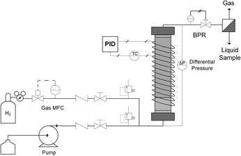
A typical up-flow packed bed design (Fig. 1) was implemented with a hydrogen-specific thermal mass flow controller (MFC) calibrated to 60 sccm flow (Sierra SmartTrak 100). Liquid flow was supplied with a dual piston HPLC pump (Series 1500) with maximum flow rate of 5 mL min−1 and maximum pressure of 6000 psi. For safety and to ensure no backflow, a 1000 psi check valve were placed in the gas line, and two 250 psi pressure relief ports were installed upstream of the reactor on both gas and liquid inlet lines. In addition, two manual valves were inserted in each gas and liquid line to release system pressure in case of clogging. The gas and liquid were mixed in a tee junction immediately prior to entering the μPBR. All tubing was perfluoroalkoxy (PFA) with outer diameter (OD) of 1/16 inch and inner diameter (ID) of 0.03 inches. The PBR was wrapped with high temperature resistive heating tape (39 W, 120 VAC), well-insulated and connected to a control loop with an Omega proportional-integral-derivative (PID) temperature controller (CN9600) and type K thermocouple in contact with the external surface of the PBR to maintain isothermal reaction conditions. Two pressure transducers (Omega PX409) were placed in the inlet and outlet of the reactor to allow for online monitoring of the pressure drop. A back pressure regulator (Equilibar, EB1LF1-SS316) was placed downstream of the reactor to regulate system pressures (±3 psi). Reaction effluent was collected directly into 2 mL vials at ambient pressure, allowing the hydrogen to vent while capturing the liquid product mixture.The fixed catalytic bed was contained within a tubular stainless steel reactor vessel comprised of a 1/4 inch diameter stainless steel tube with an inner diameter of 4.6 mm (Fig. 1). To enhance gas–liquid dispersion at the reactor inlet, the gas and liquid streams were combined immediately prior to the bed and fed into a minimal dead volume fitting with integrated 20 μm stainless steel frit. The packed bed was comprised of two sections: a calming chamber (bottom) and an active catalyst bed (upper). The calming chamber was introduced to ensure sufficient gas/liquid mixing, well-developed flow and isothermal heating prior to entrance into the catalytic zone. This region was packed with inert spherical glass beads (75 μm, SigmaAldrich 59200-U) to a depth of about 2 cm with a measured void fraction of 36.3%. The catalyst bed was packed above the calming chamber to the top of the reactor vessel (6 cm), resulting in a bed porosity of 73.2%. Exact μPBR characteristics are provided in Table 1.
| Calming Chamber | |
| Packing | Glass beads |
| Particle size | D p = 75 μm |
| Bed weight | 0.522 g |
| Bed height | 2 cm |
| Bed volume | 0.33 ml |
| Void fraction | 36.3% |
| Catalyst Bed | |
| Catalyst | Pd/silica (Silicycle) |
| Particle size | 150 μm < Dp < 212 μm |
| Catalyst weight | 0.431 g |
| Catalyst bed height | 6 cm |
| Empty volume | 0.98 mL |
| Catalyst volume | 0.26 mL |
| Void fraction | 73.2% |
Start-up, operation, and shut-down
The reactant N-4-nitrophenyl nicotinamide was prepared as a 0.1 mol L−1 stock solution in DMAc. The PBR was pre-wetted by flowing DMAc, then drained by flowing H2 gas. Back pressure was then set and liquid was reintroduced while simultaneously raising system temperature. After purging to waste 5–7 reactor volumes, the system achieves steady state and a sample was collected. Reactor variables are then adjusted and allowed to reach steady state again before obtaining the next sample. When all desired data for each reaction condition had been acquired, heaters were turned off and system pressure was reduced to atmospheric by releasing the back pressure. After the system was depressurized and adequately purged by H2, a mixture of H2 gas and DMAc solvent was flowed through PBR to fully flush/clean the μPBR system. After cooling to room temperature, manual valves were closed to isolate the reactor from atmosphere to preserve the bed and prevent oxidation of the catalyst by air. Catalysts were regenerated in situ prior to data collection (Fig. S-9, ESI†) according to standard methods,24 and all parameters were allowed to reach steady state prior to sampling.Mass transfer in three-phase reactor
In the three phase catalytic reaction system, mass transfer of gas reactants typically includes three steps in series: gas–liquid dissolution of H2, diffusion of dissolved H2 through liquid to the solid catalyst surface and intra-particle diffusion to the active catalytic sites.First, external mass transfer of hydrogen molecules from the gas to liquid to solid is considered. To characterize the transport timescale in the system, the catalytic hydrogenation of α-methylstyrene to cumene was investigated, as described in similar systems.25 This reaction was considered due to the well-known and fast intrinsic reaction kinetics enabling the study of H2 mass transfer inside the reactor. To most closely match experimental conditions, the α-methyl styrene hydrogenation was performed in DMAc solvent at 100 °C under 150 psi pressure with various flow conditions to mimic reaction conditions. Steady state profiles were fitted to standard reaction-transport models (section S3.2, ESI†), and overall mass transfer coefficient of H2 are reported to be between 1.0–5.4 s−1, as summarized in Table 2. This range falls within the expected regime reported for similar systems.26
| Liquid [mL min−1] | Gas [sccm] | (kma)GLS [s−1] |
|---|---|---|
| 0.4 | 12 | 1.0 |
| 0.4 | 36 | 2.3 |
| 0.4 | 60 | 2.5 |
| 0.8 | 24 | 2.1 |
| 1.2 | 36 | 3.2 |
| 1.6 | 48 | 4.3 |
| 2.0 | 60 | 5.4 |
Potential diffusion limitations within the porous media were evaluated by calculating the Weisz modulus (Mw), which ratios the effective reaction time and the diffusion time within the catalyst particle. The modulus was determined for both hydrogen and the starting material from the apparent reaction rate (experimental) and effective diffusivity (calculation by Wilke–Chang correlation27), as shown in Table S-1 in ESI.† The values for the Weisz modulus were determined to be 0.125 and 0.689, for H2 and N-4-nitrophenyl-nicotinamide, respectively, indicating only minor contributions from intraparticle diffusion.28
Residence time distribution (RTD) studies
To accurately describe the reaction rates and catalytic reactivity, the mean residence time, liquid holdup and dispersion in the active catalyst bed of the three-phase reactor was determined by performing residence time distribution (RTD) studies. Briefly, a 40 μL toluene tracer was injected into the liquid inlet as a single slug with a 6-port valve/sample loop configuration placed in the liquid line before the reactor inlet. The tracer was detected in fractionated samples from the reactor effluent collected for 20 time points in intervals between 15–60 s. RTD Experiments were run in two systems: (1) the packed bed reactor containing both calming chamber and catalyst bed, and (2) a shortened bed in identical configuration with only the calming chamber present. Deconvolution of dispersion and hold-up contributions in the active catalyst bed region of the packed bed reactor from the intlet/outlet fittings and calming chamber was then assessed by mathematical deconvolution of the bypass RTD. The resulting distribution was the true RTD of the catalytically active zone. Offline gas chromatography was used to assess tracer concentrations in the liquid phase in RTD studies. An HP 6890 with flame ionization detector and HP-5MS column were used to achieve separation with a standard ramping method (inlet = 20 °C, oven = 70–300 °C for 4 min, F = 1 mL min−1 He). The liquid hold-up was determined to be 74–84% within the packed bed, as summarized in Table 3. Further explanation, raw data and sample model fits are shown in section S4 in the ESI.†Catalytic reaction performance
Reactor effluent was sampled dropwise at ambient pressure and near ambient temperatures to remove selectively the gaseous hydrogen downstream of the back pressure regulator. The reactant and products in the hydrogenation reaction mixture were analysed by high pressure liquid chromatography (HPLC) (Agilent, 1200 series) equipped with a multiple wavelength UV-Vis detector (Agilent G1365D) and Quadrupole mass spectrometry detector (Agilent 6120). A reversed-phase Eclipse Plus C18 column (Agilent, 3.5 μm, 4.6 × 150 mm) was used with gradient acetonitrile/water mixture (from 90% water to 10% water) as the eluent at a flow rate of 1 mL min−1. Identification of reactant and product species was assessed by mass spectrometry and standard retention time matching.Linear calibration curves for determining the concentration of reactant (A) and product (P) (Scheme 1), were constructed by plotting the peak area versus the concentration of all standard compounds. Reactant A was characterized at maximum absorbance peak position of 330 nm, while product P was analyzed at 265 nm. The solutions were diluted 20 times to be within the linear detection range. The conversion and product yields at steady-state under each flow condition were calculated referenced to the original concentration of the starting material (0.1 mol L−1). Yield was determined as the concentration ratio of the final product concentration to the initial starting material.
Reaction intermediates observed by HPLC-MS were further separated by preparative thin layer chromatography (TLC) using a mixture of dichloromethane/methanol (4![[thin space (1/6-em)]](https://www.rsc.org/images/entities/char_2009.gif) :
:![[thin space (1/6-em)]](https://www.rsc.org/images/entities/char_2009.gif) 1) as the mobile phase. Component fractions were extracted, dissolved in dichloromethane/methanol (4
1) as the mobile phase. Component fractions were extracted, dissolved in dichloromethane/methanol (4![[thin space (1/6-em)]](https://www.rsc.org/images/entities/char_2009.gif) :
:![[thin space (1/6-em)]](https://www.rsc.org/images/entities/char_2009.gif) 1) and analyzed with NMR (Bruker AVANCE III HD b400) for identification. The sample mixture was also confirmed by TLC interface (CAMAG) with MS (Advion, expression CMS). See section S5 of the ESI† for detailed characterization methods.
1) and analyzed with NMR (Bruker AVANCE III HD b400) for identification. The sample mixture was also confirmed by TLC interface (CAMAG) with MS (Advion, expression CMS). See section S5 of the ESI† for detailed characterization methods.
Results and discussion
The catalytic hydrogenation of N-4-nitrophenyl nicotinamide over Pd/SiO2 was assessed under various reaction conditions to determine optimal chemoselective conversion to N-4-aminophenyl nicotinamide. Key reactor operating parameters for optimization included multiphase flow regimes, reactor residence times, temperature and pressure.Catalyst characterization
First, catalysts were fully characterized. High resolution TEM (Fig. 2(a)) reveals highly dispersed palladium nanoparticles within a porous silica support. Quantification by contrast-adjusted image analysis of a random distribution of metal particles identifies the average nanoparticle size to be 6.0 ± 1.8 nm in the fresh catalyst. Measured by Atomic Absorption Spectroscopy (AAS), the metal loading is determined to be 0.55 wt%. Further characterization by nitrogen physisorption (Fig. S-3, ESI†) reveals a large amount of hysteresis, indicating the presence of a substantial fraction of mesopores, leading to the high observed surface areas (∼640 m2 g−1). Table 4 gives a summary of physical characterization of the catalyst.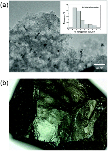 | ||
| Fig. 2 Catalyst characterization. (a) TEM of 6 nm Pd nanoparticles on silica support, (b) 300 μm single particle micrograph. | ||
| Characterization | Value | Units | Method |
|---|---|---|---|
| Surface area | 640 | m2 g−1 | BET |
| Pd loading | 0.55 | wt% | AAS |
| Pd surface area | 0.25 | m2 g−1 | CO chemisorption |
| Pd nanoparticle diameter | 6 | nm | TEM |
| Catalyst density | 0.463 | g mL−1 | SiliCycle analysis |
| Pore volume | 0.88 | mL g−1 | BJH model |
| Pore diameter | 5.4 | nm | BJH model |
The Pd–silica catalysts life is extremely important for the practical use of packed bed reactors. The Pd–silica catlaysts in packed bed reactors can be readily regenerated in situ by flowing air to burn off the accumulated coke and then by hydrogen to reduce Pd for the next reaction cycles. (ESI, section S6†).
Multiphase flow optimization
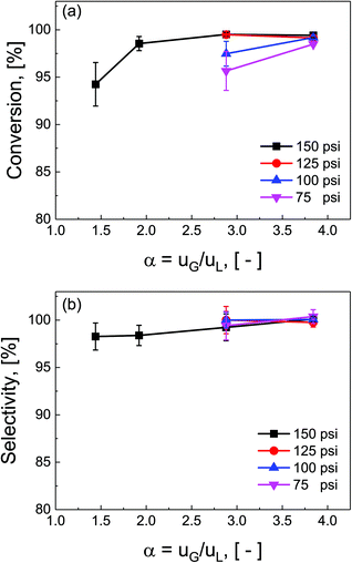
Ratios of superficial gas to liquid velocities (α = uG/uL), were systematically varied from 1.5 to 4.0, while holding liquid flow rate constant. The experimentally observed optimal operating ratio is defined here as the minimum ratio of gas to liquid superficial velocities at which maximal conversion and selectivity is obtained.As shown in Fig. 3(a) and (b), increasing gas-to-liquid flow rate ratios results in improved conversion and selectivity under all four pressure conditions studied. Lower ratios of gas to liquid velocities α did not provide sufficient gas flow to obtain the desired catalytic performance. At pressure of 75 and 100 psi, ratios of α = 3.8 were required to achieve this optimal operating criteria, while at high pressure (150 psi), this criteria was nearly met even at α = 1.9. This high conversion at elevated pressure is directly attributed to the enhanced solubility of H2 in DMAc under higher pressures in accordance with Henry's law.29 At lower pressure, higher gas flow rates are required to overcome the interfacial mass transfer limitations.
Additionally, the complex three-phase hydrodynamics and interfacial mass transfer within micro-packed beds are known to be highly dependent on the flow and pressure conditions.21 Specifically, transition away from the classical trickle-bed regimes is observed with large liquid hold-up and preferential gas-channelling in the small systems. In our study, by tuning the ratio of superficial gas velocity to superficial liquid velocity (α = uG/uL), however, it is possible to decrease liquid holdup, and enhance gas–liquid mass transfer. Evidence of regime changes from stable (mostly liquid) to chaotic flow (more pulsation) is observed in substantial deviations in pressure drop characteristics under varied flow conditions (section S7, ESI†).
Reaction pathway evaluation
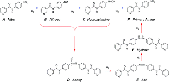
The hydrogenation of the reactant N-4-nitrophenyl nicotinamide can occur at several reducible functional groups: nitro, pyridyl and phenylene. Additionally, the nitro group can be partially or totally reduced to the primary amine. As is typical with more harsh reducing catalysts (i.e., Pt), the pyridyl group can reduce to a partially or completely saturated ring. In this work, a mild reducing catalyst, palladium, is used to achieve highly chemo-selective hydrogenation of the nitro group to a primary amine. In the present study, the hydrogenation of pyridyl and phenylene groups were not observed.Over precious metal catalysts, the mechanism for small molecule nitroarene hydrogenation has been discussed in detail by Corma et al. and shown to potentially progress through several competitive pathways.30,31 In the first mechanism (direct), two consecutive fast hydrogenations of the nitro group to the nitroso and hydroxyl-amine compounds occur before undergoing the slow final reduction to the primary amine. In contrast, the second mechanism (condensation) circumvents the slow step by condensing the two hydrogenation products into an azoxy compound which can be more easily deoxygenated and reduced before undergoing a final cleavage to form two monomeric primary aromatic amines. A similar mechanism is proposed here (Scheme 2), whereby the starting material (A) undergoes either three consecutive direct hydrogenations (top pathway) or proceeds by dimerization and consecutive hydrogenation (bottom pathway).
A single dominant, stable intermediate was observed to accumulate, especially at low conversion with low yield to the desired primary amine product. The molecule was identified by mass spectrometry to have a parent peak with m/z = 438 and confirmed to be the dimeric azoxy compound (D) by isolation by TLC and subsequent NMR (ESI section S5†). This is consistent with established mechanisms observed with nitroarene hydrogenation.30,32,33
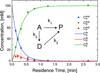
The reaction in the micro-packed bed reactor was operated under flow conditions giving rise to operation with several residence times while maintaining constant gas-to-liquid ratio, pressure and temperature. Concentrations of the unreacted starting material (A), azo intermediate (D) and primary amine product (P) were quantified using HPLC with total mass balance closures >93% for all residence times examined. Notably, no appreciable amounts of species (B) and (C) were detected, as is consistent with the expected fast kinetic steps.30 Concentration profiles of each species are plotted versus mean liquid residence time in Fig. 4. It is observed that as the residence time is increased there is a drop in the reactant concentration with a simultaneous increase in the concentrations of the intermediate dimer and product at steady state. The dimer that accumulates at short residence times, however reacts to completion to form product (P) at higher residence times. Such profiles are typical for irreversible reactions progressing through a stable intermediate, indicating that the reaction mechanism at least in part progresses through the lower reaction pathway.
To quantify the relative contributions of the two kinetic pathways to the overall production rate of product P, a simplified version of Scheme 2 (kinetic model, inset Fig. 4) describing the reactant (A), azo intermediate (D) and primary amine product (P) was developed and applied to a dispersion-reaction packed bed reactor model. The full derivation is shown in the ESI (section S8†).
The resulting molar fluxes indicate that the relative reaction flux to the product predominately passes through the reaction intermediate D (88%). The lumped kinetic rate constants from kinetic flux analysis are determined to be k1 = 0.31 min−1, k2 = 2.25 min−1, k3 = 11.07 min−1. This result indicates that the dominant reaction pathway for liquid-phase hydrogenation of the nitro group in N-4-nitrophenyl nicotinamide progresses through an azo-dimer formation before cleaving to two reduced primary amines. However, this pathway alone cannot describe the experimentally observed kinetics, indicating that competitive progression through the direct catalytic pathway is likely.
Reaction optimization
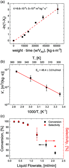
For optimization purposes, the model is further simplified to describe only the rate determining step (i.e. dimer formation). See ESI section S8† for derivation. By varying the gaseous and liquid flow rates between 6.1–61.0 sccm and 0.21–2.11 mL min−1, respectively, reaction progression can be monitored from the steady state conversions at several RTD-corrected weight times. As shown in Fig. 5(a), the reactant conversion increases linearly with weight-time in accordance with eqn (S15),† further validating the first order kinetic approximation. Linearizing this relationship, the apparent reaction rate constant is measured to be k′ = 9.6 × 10⁻⁵ m3 (kg−1)catalyst s−1.To achieve more rapid catalytic turnover with high product yields, it is desirable to operate hydrogenation reactions at high temperatures (>200 °C). However, reactors operating at such temperatures may demonstrate relatively slower mass transfer limitations, or diminished product selectivity due to the increased rate of secondary hydrogenations. Although both reaction conversion and transport rates benefit from the increase of temperature, reaction kinetics are known to be strongly activated, increasing exponentially with temperature in accordance with the Arrhenius relationship:
| krxn ∝ exp (−Ea/RT) |
Reactions were performed at temperatures from 25–100 °C at constant superficial gas to liquid ratios of 2.9 and pressure of 150 psig. At each temperature, apparent rates were calculated according to eqn (S15)† and apparent rate constants were extracted and plotted for the various temperatures (Fig. 5(b)). The data showed strong agreement with the Arrhenius relationship, demonstrating a constant activation energy of Ea = 48.4 ± 3.0 kJ mol−1. This value represents a single rate limiting activated reaction step, with a magnitude typical of bulk supported and network stabilized Pd (Ea = 43–45 kJ mol−1).34–36 Additionally, values for apparent rate constants are substantially slower than the fast mass transfer (Table 2 and ESI section S3†). Furthermore, activation energies are substantially higher, again affirming that our observed rate limitation is not due to transport limitations, but rather a reaction limitation.
By carefully tuning pressure, residence time and temperature, quantitative conversion and selectivity are realized for the hydrogenation of N-4-nitrophenyl nicotinamide to N-4-aminophenyl nicotinamide, as demonstrated at elevated temperatures in Fig. 5(c).
Conclusions
Highly dispersed sol–gel-entrapped Pd nanoparticles within a microporous organic/silica support have been demonstrated to exhibit excellent activity and chemoselectivity for the hydrogenation of nitroarenes in a small molecule API surrogate. The use of micro-packed beds provided enhanced mass transfer in the multiphase micro-system, enabling continuous flow chemistry under rapid kinetic control. The bench scale platform offered the benefit of both enabling rapid screening across a wide parameter space (pressure, temperature, residence times, flow regimes, etc.), as well as exhibiting performance at rates directly relevant to small-scale industrial pharmaceutical production (0.1–1 kg day−1). From a mechanistic perspective, kinetics for the liquid phase hydrogenation were elucidated to reveal that the chemistry progresses through the classical dimerization and subsequent series reduction steps to produce the primary amine. Finally, operation under optimized conditions (high pressure, high temperature, long residence times and/or high gas-to-liquid flow rates), direct reduction with hydrogen gas was demonstrated to achieve quantitative yields toward the primary amine in the absence of costly/toxic reducing agents, homogeneous catalysts, or hazardous pressurized batch reactors.Conflicts of interest
There are no conflicts to declare.Acknowledgements
The authors would like to acknowledge the financial support of the Novartis-MIT Center for Continuous Manufacturing. Silicycle (2500 Parc-Technologique Blvd., Quebec City (Quebec) G1P 4S6, Canada) for their generous donation of the Pd catalyst. Additionally, Andrea Adamo, Isaac Roes and the Jamison Lab (MIT) are acknowledged for assistance with the gas/liquid separation, RTD system design, and chemical characterization, respectively.References
- K. P. Cole, J. M. Groh, M. D. Johnson, C. L. Burcham, B. M. Campbell, W. D. Diseroad, M. R. Heller, J. R. Howell, N. J. Kallman, T. M. Koenig, S. A. May, R. D. Miller, D. Mitchell, D. P. Myers, S. S. Myers, J. L. Phillips, C. S. Polster, T. D. White, J. Cashman, D. Hurley, R. Moylan, P. Sheehan, R. D. Spencer, K. Desmond, P. Desmond and O. Gowran, Science, 2017, 356, 1144–1150 CrossRef CAS PubMed.
- N. Zaborenko, R. J. Linder, T. M. Braden, B. M. Campbell, M. M. Hansen and M. D. Johnson, Org. Process Res. Dev., 2015, 19, 1231–1243 CrossRef CAS.
- S. Mascia, P. L. Heider, H. Zhang, R. Lakerveld, B. Benyahia, P. I. Barton, R. D. Braatz, C. L. Cooney, J. M. Evans, T. F. Jamison, K. F. Jensen, A. S. Myerson and B. L. Trout, Angew. Chem., Int. Ed., 2013, 52, 12359–12363 CrossRef CAS PubMed.
- C. Jiménez-González, P. Poechlauer, Q. B. Broxterman, B.-S. Yang, D. am Ende, J. Baird, C. Bertsch, R. E. Hannah, P. Dell'Orco, H. Noorman, S. Yee, R. Reintjens, A. Wells, V. Massonneau and J. Manley, Org. Process Res. Dev., 2011, 15, 900–911 CrossRef.
- K. F. Jensen, AIChE J., 2017, 63, 858–869 CrossRef CAS.
- T. D. White, K. D. Berglund, J. M. Groh, M. D. Johnson, R. D. Miller and M. H. Yates, Org. Process Res. Dev., 2012, 16, 939–957 CrossRef CAS.
- P. Poechlauer, J. Colberg, E. Fisher, M. Jansen, M. D. Johnson, S. G. Koenig, M. Lawler, T. Laporte, J. Manley, B. Martin and A. O'Kearney-McMullan, Org. Process Res. Dev., 2013, 17, 1472–1478 CrossRef CAS.
- M. B. Plutschack, B. Pieber, K. Gilmore and P. H. Seeberger, Chem. Rev., 2017, 117, 11796–11893 CrossRef CAS PubMed.
- S. V. Ley, D. E. Fitzpatrick, R. M. Myers, C. Battilocchio and R. J. Ingham, Angew. Chem., Int. Ed., 2015, 54, 10122–10136 CrossRef CAS PubMed.
- R. J. Ingham, C. Battilocchio, D. E. Fitzpatrick, E. Sliwinski, J. M. Hawkins and S. V. Ley, Angew. Chem., Int. Ed., 2015, 54, 144–148 CrossRef CAS PubMed.
- B. Gutmann, D. Cantillo and C. O. Kappe, Angew. Chem., Int. Ed., 2015, 54, 6688–6728 CrossRef CAS PubMed.
- M. D. Johnson, S. A. May, J. R. Calvin, J. Remacle, J. R. Stout, W. D. Diseroad, N. Zaborenko, B. D. Haeberle, W.-M. Sun, M. T. Miller and J. Brennan, Org. Process Res. Dev., 2012, 16, 1017–1038 CrossRef CAS.
- J. S. Carey, D. Laffan, C. Thomson and M. T. Williams, Org. Biomol. Chem., 2006, 4, 2337–2347 CAS.
- M. Yalpani, T. Lunow and R. Köster, Chem. Ber., 1989, 122, 687–693 CrossRef CAS.
- C. A. Brown and V. K. Ahuja, J. Org. Chem., 1973, 38, 2226–2230 CrossRef CAS.
- P. J. Dauenhauer, J. R. Salge and L. D. Schmidt, J. Catal., 2006, 244, 238–247 CrossRef CAS.
- A. Pintar and J. Batista, Catal. Today, 1999, 53, 35–50 CrossRef CAS.
- E. Crezee, B. W. Hoffer, R. J. Berger, M. Makkee, F. Kapteijn and J. A. Moulijn, Appl. Catal., A, 2003, 251, 1–17 CrossRef CAS.
- M. W. Losey, M. A. Schmidt and K. F. Jensen, Ind. Eng. Chem. Res., 2001, 40, 2555–2562 CrossRef CAS.
- R. M. Machado, K. R. Heier and R. R. Broekhuis, Curr. Opin. Drug Discovery Dev., 2001, 4, 745–755 CAS.
- J. Zhang, A. R. Teixeira, L. T. Kögl, L. Yang and K. F. Jensen, AIChE J., 2017, 63, 4694–4704 CrossRef CAS.
- A. J. Kasparian, C. Savarin, A. M. Allgeier and S. D. Walker, J. Org. Chem., 2011, 76, 9841–9844 CrossRef CAS PubMed.
- G. B. af Gennas, L. Mologni, S. Ahmed, M. Rajaratnam, O. Marin, N. Lindholm, M. Viltadi, C. Gambacorti-Passerini, L. Scapozza and J. Yli-Kauhaluoma, ChemMedChem, 2011, 6, 1680–1692 CrossRef PubMed.
- K. B. van Gelder, J. K. Damhof, P. J. Kroijenga and K. R. Westerterp, Chem. Eng. Sci., 1990, 45, 3159–3170 CrossRef CAS.
- M. T. Kreutzer, P. Du, J. J. Heiszwolf, F. Kapteijn and J. A. Moulijn, Chem. Eng. Sci., 2001, 56, 6015–6023 CrossRef CAS.
- S. Haase, M. Weiss, R. Langsch, T. Bauer and R. Lange, Chem. Eng. Sci., 2013, 94, 224–236 CrossRef CAS.
- R. C. Reid and T. K. Sherwood, Properties of Gases and Liquids, McGraw-Hill Inc., 1966 Search PubMed.
- O. Levenspiel, Chemical Reactor Omnibook, Oregon State University Bookstore, 2002 Search PubMed.
- G. L. Rempel, Doctor of Philosophy, The University of British Columbia, 1968 Search PubMed.
- A. Corma, P. Concepción and P. Serna, Angew. Chem., Int. Ed., 2007, 46, 7266–7269 CrossRef CAS PubMed.
- A. Corma and P. Serna, Science, 2006, 313, 332–334 CrossRef CAS PubMed.
- H.-U. Blaser, Science, 2006, 313, 312–313 CrossRef CAS PubMed.
- H.-U. Blaser, H. Steiner and M. Studer, ChemCatChem, 2009, 1, 210–221 CrossRef CAS.
- S. Arora, P. Kapoor and M. L. Singla, Reaction Kinetics, Mechanisms and Catalysis, 2010, 99, 157–165 Search PubMed.
- Y. Mei, G. Sharma, Y. Lu, M. Ballauff, M. Drechsler, T. Irrgang and R. Kempe, Langmuir, 2005, 21, 12229–12234 CrossRef CAS PubMed.
- Y. Mei, Y. Lu, F. Polzer, M. Ballauff and M. Drechsler, Chem. Mater., 2007, 19, 1062–1069 CrossRef CAS.
Footnote |
| † Electronic supplementary information (ESI) available: Synthesis, characterization and experimental methods, supporting experiments and model derivations. See DOI: 10.1039/c7gc03469e |
| This journal is © The Royal Society of Chemistry 2018 |


