Polarization energy of two charged dielectric spheres in close contact
Huada
Lian
 a and
Jian
Qin
 *b
*b
aDepartment of Materials Science and Engineering, Stanford University, Stanford, California 94305, USA
bDepartment of Chemical Engineering, Stanford University, Stanford, California 94305, USA. E-mail: jianq@stanford.edu
First published on 27th October 2017
Abstract
Evaluating the interaction energy between charged dielectric spheres in close contact is difficult because interfacial charge polarization becomes increasingly stronger as separation decreases. The limit of high dielectric permittivity is amenable to theoretical treatment because the particles become equipotential upon close contact. For particles with low permittivity, the constitutive equation for the induced surface charges demanded by the boundary conditions is derived in this work, based on which the contact energy of symmetric cases is evaluated. The known result for conducting spheres is recovered as a limiting case.
Design, System, ApplicationSuccessful design of the structural stability of molecular systems needs to be based on a thorough understanding of the inter-component interactions. This work focuses on the strong, nearly singular polarization interaction between charged dielectric spheres in close contact. The polarization interaction is caused by the surface charges accumulated at the interfaces between the particles and medium, which exhibit distinct dielectric permittivities. The interaction was known to be strong and singular for conducting spheres. We consider dielectric spheres and develop an analytical formalism that reveals a similar type of singularity and allows for calculation of polarization energy at small separations. For two spheres of equal size and charges, we evaluate the cohesive energy and show that the result includes the conducting case as a special example. |
1 Introduction
Bringing two conducting spheres of identical size into contact produces a cohesive energy | (1) |
![[thin space (1/6-em)]](https://www.rsc.org/images/entities/char_2009.gif) ln
ln![[thin space (1/6-em)]](https://www.rsc.org/images/entities/char_2009.gif) 2)a is the total capacitance of the two spheres in contact. The subtracted term (Q12 + Q22)/(2a) is the self-polarization energy of two distant spheres. Eqn (1) was known to Maxwell,1 and was re-considered later.2,3 The main conclusion was that when the charges carried by the two spheres produce a difference in electrostatic potential upon close contact, the induced polarization charges near the contact increase in amplitude according to
2)a is the total capacitance of the two spheres in contact. The subtracted term (Q12 + Q22)/(2a) is the self-polarization energy of two distant spheres. Eqn (1) was known to Maxwell,1 and was re-considered later.2,3 The main conclusion was that when the charges carried by the two spheres produce a difference in electrostatic potential upon close contact, the induced polarization charges near the contact increase in amplitude according to  , where d is the gap distance. As a result, the majority of the potential difference is established when the two spheres are close to each other. This weak singularity as d → 0 leads to a strong separation dependence in energy, and makes accurate calculation of cohesive energy between two conducting spheres difficult. The same type of contact singularity is present in clusters of multiple conducting spheres, for which a generalized approach that combines the Derjaguin approximation with numerical extrapolation has been employed to evaluate the capacitance coefficients and the cohesive energy.4
Despite extensive efforts for dielectric particles,5–7 no analogous results on contact energy have been reported. When dielectric spheres have large separation, the polarization energy can be calculated by approximating the induced polarization charges as dipoles or, as separation decreases, as a sum of multipoles. A systematic approach based on multiple-scattering formalism has been developed to calculate the polarization energy of many polarizable spheres, which carry monopolar, dipolar or multipolar charges.8–10 This approach expresses the total electrostatic energy of dielectric spheres carrying charges of ideal multipoles as a sum of two-body, three-body and other interactions. The two-body terms are normal Coulomb interactions. The three-body terms are interactions between two spheres mediated by one polarizable surface. The four-body terms involve two polarizable surfaces, and the higher order terms are constructed analogously. Each of these terms can be efficiently evaluated by using image lines.8,10 At a scaling level, the two-body terms are proportional to the inverse of average separation R = ρ−1/3 between spheres, where ρ is the number density of spheres. The three-body terms are smaller by a factor (a/R)−3. Each higher order term is smaller by an additional factor (a/R)−6.
Therefore, it is expected that the three-body terms are sufficient for dilute systems or for spheres at large separation. As average separation increases, however, higher order terms become increasingly more relevant. Upon close contact, essentially all the higher order polarization interactions are needed, which is the origin of the singular behavior identified for contact energy between conducting spheres. For dielectric spheres, since the Derjaguin approximation4 cannot be applied to obtain the contact charge—the dielectrics are not equipotential—the contact singularity cannot be readily identified. Preliminary numerical calculation based on multiple-scattering formalism has revealed the difficulty of resolving this contact energy: in one case, the number of higher order polarization terms increases with reduced separation;9 in another, greater spatial resolution is needed.5
This work aims at calculating the contact energy between two charged dielectric spheres. Instead of relying on the perturbative multiple-scattering approach for electrostatic potential, the boundary conditions demanded by the induced surface charges are derived using a bispherical coordinate system. Then, the potential and energy are calculated from the induced charges for varying inter-particle separations. The expressions for elastance coefficients are derived. The contact energy for spheres with arbitrary dielectric permittivity εin is evaluated. It is demonstrated that, in the conducting limit, i.e., εin → ∞, the contact energy reduces to that of Maxwell's result (eqn (1)). The dependence on permittivity allows one to estimate the cohesive energy for dielectric dimers carrying symmetric charges.
2 Formalism
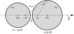
We consider two dielectric spheres with radius a1 and a2, each carrying a fixed charge distribution inside the sphere. An arbitrary charge distribution can be expanded in terms of multipoles. The multipoles can be projected onto surface charges. In order to calculate the total energy of a system of polarizable particles, it suffices to consider particles with embedded multipoles and apply the superposition principle. The formalism developed below can be applied to particles with embedded multipoles. For simplicity, we focus on monopolar particles, i.e., each sphere carries a net charge, Q1 and Q2, which is evenly distributed on the surface. The electrostatic potential outside the sphere generated by such surface charges is identical to that generated by a point source placed at the center of the sphere.The particle configuration is sketched in Fig. 1. The dielectric permittivity inside and outside the two spheres are εin and εout, respectively. We are interested in the variation of polarization energy with gap distance d. At a large distance, the energy is the total of self-polarization energy of two isolated spheres,  , which is caused by the interaction between the charges Q1 and Q2 and the induced surface charges on their own surfaces. At a reduced distance, the normal Coulomb energy, E∞ = Q1Q2/(4πεoutR12), is needed. In the limit of close contact, d → 0, the mutual polarization interaction becomes relevant.8 Evaluating the energy and electrostatic potential requires solving the boundary value problem for Poisson's equation explicitly.11
The boundary condition is conveniently formulated using the bispherical coordinate system,12 parameterized by (σ, τ, ϕ). Here, 0 ≤ σ ≤ π is the angle spanned between two foci located at (0, 0, −b) and (0, 0, +b). The term −∞ < τ ≡ ln(d−/d+) < ∞ is defined based on the ratio of distance d− to foci (0, 0, −b) and distance d+ to foci (0, 0, +b), so that τ > 0 in half space z > 0, τ < 0 in half space z < 0, and τ = 0 in the x–y plane. The azimuthal angle is defined by 0 ≤ ϕ < 2π.
The surfaces of the two spheres in Fig. 1 have a constant τ value: τ = ζ > 0 and τ = −η < 0. The coordinates of points on the surface satisfy x2 + y2 + (z − b coth τ)2 = (b csch τ)2. The two spheres approach each other when ζ and η both approach zero. The center of sphere τ is (0, 0, b coth τ) in Cartesian and (0, 2τ, 0) in bispherical coordinate systems. The scale factors for coordinates σ, τ and ϕ are
 | (2) |
![[thin space (1/6-em)]](https://www.rsc.org/images/entities/char_2009.gif) σ
σ![[thin space (1/6-em)]](https://www.rsc.org/images/entities/char_2009.gif) cos
cos![[thin space (1/6-em)]](https://www.rsc.org/images/entities/char_2009.gif) ϕ, sin
ϕ, sin![[thin space (1/6-em)]](https://www.rsc.org/images/entities/char_2009.gif) σ
σ![[thin space (1/6-em)]](https://www.rsc.org/images/entities/char_2009.gif) sin
sin![[thin space (1/6-em)]](https://www.rsc.org/images/entities/char_2009.gif) ϕ, sinh
ϕ, sinh![[thin space (1/6-em)]](https://www.rsc.org/images/entities/char_2009.gif) τ). The distance between two points (σ, τ, ϕ) and (σ1, τ1, ϕ1) is
τ). The distance between two points (σ, τ, ϕ) and (σ1, τ1, ϕ1) is[2hσhσ1(cosh(τ − τ1) − cos![[thin space (1/6-em)]](https://www.rsc.org/images/entities/char_2009.gif) γ)]1/2, γ)]1/2, | (3) |
![[thin space (1/6-em)]](https://www.rsc.org/images/entities/char_2009.gif) γ = cos
γ = cos![[thin space (1/6-em)]](https://www.rsc.org/images/entities/char_2009.gif) σ
σ![[thin space (1/6-em)]](https://www.rsc.org/images/entities/char_2009.gif) cos
cos![[thin space (1/6-em)]](https://www.rsc.org/images/entities/char_2009.gif) σ1 + sin
σ1 + sin![[thin space (1/6-em)]](https://www.rsc.org/images/entities/char_2009.gif) σ
σ![[thin space (1/6-em)]](https://www.rsc.org/images/entities/char_2009.gif) sin
sin![[thin space (1/6-em)]](https://www.rsc.org/images/entities/char_2009.gif) σ1
σ1![[thin space (1/6-em)]](https://www.rsc.org/images/entities/char_2009.gif) cos(ϕ − ϕ1).
cos(ϕ − ϕ1).
By introducing the surface charge densities ρζ and ρη into the two spheres, the electrostatic potential ϕ(r) at position r can be written as a sum:
 | (4) |
Here, ϕ0(r) is the potential of source charges,
 | (5) |
 | (6) |
Here, εr ≡ εin/εout is the ratio of dielectric permittivities inside and outside the particle. It is clear that ρη can be interpreted as (1 − εr)n·∇ϕ(r(Sη)) and ρζ as (1 − εr)n·∇ϕ(r(Sζ)).
Eqn (4) is a formal solution for Poisson's equation valid at all separations. We are particularly interested in the limit when separation d = R12 − a1 − a2 is smaller compared to both radii, a1 and a2. In the bispherical coordinate system, this can be achieved by setting b → 0. At the same time, to keep a1 = b/sinh![[thin space (1/6-em)]](https://www.rsc.org/images/entities/char_2009.gif) ζ and a2 = b/sinh
ζ and a2 = b/sinh![[thin space (1/6-em)]](https://www.rsc.org/images/entities/char_2009.gif) η constant, b needs to be of the same order as sinh
η constant, b needs to be of the same order as sinh![[thin space (1/6-em)]](https://www.rsc.org/images/entities/char_2009.gif) ζ ∼ ζ or sinh
ζ ∼ ζ or sinh![[thin space (1/6-em)]](https://www.rsc.org/images/entities/char_2009.gif) η ∼ η. In the limit of close contact, we have ζ = b/a1 and η = b/a2. The distance between the two surfaces can be written as
η ∼ η. In the limit of close contact, we have ζ = b/a1 and η = b/a2. The distance between the two surfaces can be written as  , in which
  . Using a as the unit of length, we find that b/a is asymptotically small and that b/a ≃ (d/a)1/2.
2.1 Boundary conditions for surface charge
The formal solution (eqn (4)) relates four quantities ϕ(r), ϕ0(r), ρζ and ρη to each other. The source potential ϕ0(r) is given. The surface charge densities ρζ and ρη produce the discontinuity of the electric field at dielectric boundaries, i.e.,| εinEς(−) = εoutEς(+), εinEη(−) = εoutEη(+). | (7) |
 . For positive or negative τ, the above expression gives the component Eτ pointing towards the inward or outward directions.
The electrical field at the boundary of sphere ζ includes contributions E(0)ςς from the source charge in the ζ particle, E(0)ςη from the source charge in the η particle, E(s)ςς from the induced charge in the ζ particle, and E(s)ςη from the induced charge in the η particle. The electrical field at the boundary of sphere η can be decomposed similarly. Thus, we have Eς = E(0)ςς + E(0)ςη + E(s)ςς + E(s)ςη and Eη = E(0)ης + E(0)ηη + E(s)ης + E(s)ςς. The self-polarization term E(0)ςς equals  inside sphere ζ (at a1 − 0) and
  outside sphere ζ (at a1 + 0). The self-polarization term E(0)ηη equals
  inside sphere η and
  outside sphere η. They both satisfy the required boundary conditions in eqn (7) alone. On the other hand, E(0)ςη and E(s)ςη are continuous across the ζ surface, and E(s)ςς is discontinuous; similar arguments hold for the η surface. So the boundary conditions can also be written as:
 | (8) |
The subscripts “out” and “in” remind us from which side the field is evaluated.
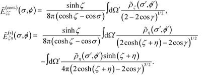
Eqn (8) serves as the basis for solving the surface charges. The source terms E(0)ςη and E(0)ης can be trivially evaluated. The remaining induced terms can all be expressed as integrals over the surface charges. For instance, the potential at an arbitrary point r = (σ, τ, ϕ) generated by the surface charge ρζ can be written as:
 | (9) |
Here, an auxiliary charge density, ![[small rho, Greek, tilde]](https://www.rsc.org/images/entities/i_char_e0e4.gif) ζ ≡ ρζ/(cosh
ζ ≡ ρζ/(cosh![[thin space (1/6-em)]](https://www.rsc.org/images/entities/char_2009.gif) ζ − cos
ζ − cos![[thin space (1/6-em)]](https://www.rsc.org/images/entities/char_2009.gif) σ′)3/2, has been introduced in order to simplify the notation. The factor cos
σ′)3/2, has been introduced in order to simplify the notation. The factor cos![[thin space (1/6-em)]](https://www.rsc.org/images/entities/char_2009.gif) γ ≡ cos
γ ≡ cos![[thin space (1/6-em)]](https://www.rsc.org/images/entities/char_2009.gif) σ
σ![[thin space (1/6-em)]](https://www.rsc.org/images/entities/char_2009.gif) cos
cos![[thin space (1/6-em)]](https://www.rsc.org/images/entities/char_2009.gif) σ′ + sin
σ′ + sin![[thin space (1/6-em)]](https://www.rsc.org/images/entities/char_2009.gif) σ
σ![[thin space (1/6-em)]](https://www.rsc.org/images/entities/char_2009.gif) sin
sin![[thin space (1/6-em)]](https://www.rsc.org/images/entities/char_2009.gif) σ′
σ′![[thin space (1/6-em)]](https://www.rsc.org/images/entities/char_2009.gif) cos(ϕ − ϕ′) is the angle cosine between unit vectors oriented along (σ, ϕ) and (σ′, ϕ′).
cos(ϕ − ϕ′) is the angle cosine between unit vectors oriented along (σ, ϕ) and (σ′, ϕ′).
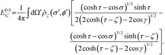
The straightforward differentiation  applied to the potential yields the electric field along the direction −
![[small tau, Greek, circumflex]](https://www.rsc.org/images/entities/i_char_e0b8.gif)
 | (10) |
 . The above expression is applicable for any value of τ, and is continuous except at τ = ζ. To resolve the magnitude of the discontinuity, we focus on the cases τ = ζ ± 0. Using the fact that
  as τ → ζ ± 0, we get
The term in the bracket is continuous across the normal direction of the surface since the logarithmic divergence arising from the weak singularity at the denominator does not depend on whether surface ζ is approached from the inside or the outside. So we denote it as E(cont.)ζζ. The second term −(±ρζ/2) shows that the discontinuity is proportional to the charge density. By our convention, ζ is positive, so the term with the positive sign, for ζ + 0, is the field inside the particle, whereas the term with the negative sign, for ζ − 0, is the field outside the particle. Using these conventions, the first line of the boundary condition, eqn (5), can be written as
It is convenient to introduce the relative dielectric discontinuity,
 , and divide both sides by (cosh
![[thin space (1/6-em)]](https://www.rsc.org/images/entities/char_2009.gif) ζ − cos
ζ − cos![[thin space (1/6-em)]](https://www.rsc.org/images/entities/char_2009.gif) σ)3/2, to convert ρ to
σ)3/2, to convert ρ to ![[small rho, Greek, tilde]](https://www.rsc.org/images/entities/i_char_e0e4.gif) and, analogously, E to
and, analogously, E to  . Then, we arrive at
 | (11) |
Apart from the dependence on free charges, the equation above is identical to eqn (31) of ref. 12.
The analogous result for particle η is obtained by exchanging η and ζ:
 | (12) |
Eqn (11) and (12) are the boundary conditions that will be solved to obtain the induced charge densities.
2.2 Mode expansion
Given the symmetry of particle boundaries, it is convenient to expand the charge densities and the normal components of the electric fields using spherical harmonics, as follows:The expansion coefficients are computed by projections, e.g.,
![[thin space (1/6-em)]](https://www.rsc.org/images/entities/char_2009.gif) σ. The convention for spherical harmonic functions Y
σ. The convention for spherical harmonic functions Y![[small script l]](https://www.rsc.org/images/entities/i_char_e146.gif) m is that they are normalized, i.e.,
m is that they are normalized, i.e.,  , where Pm
![[small script l]](https://www.rsc.org/images/entities/i_char_e146.gif) is the associated Legendre polynomial. For configurations with uniaxial symmetry, such as the case with monopolar charges, only isotropic components with m = 0 survive, and the coefficients are simply written as A
is the associated Legendre polynomial. For configurations with uniaxial symmetry, such as the case with monopolar charges, only isotropic components with m = 0 survive, and the coefficients are simply written as A![[small script l]](https://www.rsc.org/images/entities/i_char_e146.gif) , B
, B![[small script l]](https://www.rsc.org/images/entities/i_char_e146.gif) , U
, U![[small script l]](https://www.rsc.org/images/entities/i_char_e146.gif) , and V
, and V![[small script l]](https://www.rsc.org/images/entities/i_char_e146.gif) , which are evaluated using the projection on the Legendre polynomial of the form, for instance,
, which are evaluated using the projection on the Legendre polynomial of the form, for instance,  Two points are made before proceeding further. First, the expansion is applied to the quantities with ‘∼’, i.e., those normalized by (cosh
![[thin space (1/6-em)]](https://www.rsc.org/images/entities/char_2009.gif) τ − cos
τ − cos![[thin space (1/6-em)]](https://www.rsc.org/images/entities/char_2009.gif) σ)−3/2. Second, the field
σ)−3/2. Second, the field  in the most general situations includes contributions from all the sources other than those on particle ζ; here, the only external source is particle η, so η is explicitly labeled.
By substituting the above mode expansion coefficients to eqn (11) and (12), and using the expansions  and
and  , we obtain the following algebraic relation for the coefficients from the boundary conditions on sphere ζ,
 | (13) |
Here, the coefficients are defined by g![[small script l]](https://www.rsc.org/images/entities/i_char_e146.gif) ≡ e−(
≡ e−(![[small script l]](https://www.rsc.org/images/entities/i_char_e146.gif) +1/2)(ζ+η),
+1/2)(ζ+η),  , and
, and  An analogous expression can be found from the boundary conditions on sphere η. For the uniaxial case of interest here, only the m = 0 terms survive. So we drop the explicit reference to index m and adopt the convention that all the coefficients are evaluated at m = 0. Then, the constitutive equation can be written as:
 | (14) |
The coefficients C![[small script l]](https://www.rsc.org/images/entities/i_char_e146.gif)
![[small script l]](https://www.rsc.org/images/entities/i_char_e146.gif) ′ and I
′ and I![[small script l]](https://www.rsc.org/images/entities/i_char_e146.gif)
![[small script l]](https://www.rsc.org/images/entities/i_char_e146.gif) ′ are reduced to
′ are reduced to  and
and  . The corresponding constitutive equation for particle η is obtained by exchanging A and B and by replacing U with V:
 | (15) |
In the conducting limit, ε → 1, the coefficient relation can be further simplified to:
In the far field regime, ζ → ∞ and η → ∞, whereas at the same time ζ/sinh![[thin space (1/6-em)]](https://www.rsc.org/images/entities/char_2009.gif) ζ → a1 and η/sinh
ζ → a1 and η/sinh![[thin space (1/6-em)]](https://www.rsc.org/images/entities/char_2009.gif) η → a2. The cross terms all vanish because the coupling g
η → a2. The cross terms all vanish because the coupling g![[small script l]](https://www.rsc.org/images/entities/i_char_e146.gif) decays to zero.
decays to zero.
In the near field regime, ζ → 0, η → 0, b/ζ → a1 and b/η → a2; the small parameters ζ, η, and b are of the same order of magnitude. In this limit, the coefficient I![[small script l]](https://www.rsc.org/images/entities/i_char_e146.gif)
![[small script l]](https://www.rsc.org/images/entities/i_char_e146.gif) ′ is of the order
′ is of the order  . To solve the unknown A
![[small script l]](https://www.rsc.org/images/entities/i_char_e146.gif) and B
and B![[small script l]](https://www.rsc.org/images/entities/i_char_e146.gif) , the mode coefficients U
, the mode coefficients U![[small script l]](https://www.rsc.org/images/entities/i_char_e146.gif) and V
and V![[small script l]](https://www.rsc.org/images/entities/i_char_e146.gif) from the fields produced by free charges are needed. The numerical results for the conducting limit obtained from such an approach are illustrated in Fig. 2 and compared to the prediction of ref. 3.
from the fields produced by free charges are needed. The numerical results for the conducting limit obtained from such an approach are illustrated in Fig. 2 and compared to the prediction of ref. 3.
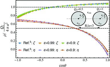 | ||
Fig. 2 Comparison of surface charge densities on two spheres with equal radius Qζ = 2Qη and separation distance R/a = 3 with known results for conducting spheres.3 The thick curves are the total densities and the dashed lines denote the free charge density, both of which have units of Qζ/4πa2. The bispherical coordinate σ is related to θ by  . The upper sign corresponds to the right half space and the lower sign corresponds to the left half space. . The upper sign corresponds to the right half space and the lower sign corresponds to the left half space. | ||
2.3 Fields U![[small script l]](https://www.rsc.org/images/entities/h3_char_e146.gif) and V
and V![[small script l]](https://www.rsc.org/images/entities/h3_char_e146.gif) from point sources
from point sources
To solve the induced surface charges, we first consider the potential ϕζ(r) at an arbitrary point r(σ, ζ, ϕ) on the surface of sphere ζ, produced by the charge Qη on sphere η, which is centered at rη = (0, −2η, 0). In the bispherical coordinate system, ϕζ(r) can be written as: | (16) |
![[thin space (1/6-em)]](https://www.rsc.org/images/entities/char_2009.gif) γ reduces to cos
γ reduces to cos![[thin space (1/6-em)]](https://www.rsc.org/images/entities/char_2009.gif) σ. The field E(0)ζ along the outward-pointing normal direction can be evaluated by applying
σ. The field E(0)ζ along the outward-pointing normal direction can be evaluated by applying  to ϕζ(r), which gives rise to the following expression for the mode coefficient:
 | (17) |
![[small script l]](https://www.rsc.org/images/entities/i_char_e146.gif) (η, ζ) is defined by:
(η, ζ) is defined by:The coefficients V
![[small script l]](https://www.rsc.org/images/entities/i_char_e146.gif) on sphere η are found by exchanging ζ and η. Completely analogous results can be obtained for V
on sphere η are found by exchanging ζ and η. Completely analogous results can be obtained for V![[small script l]](https://www.rsc.org/images/entities/i_char_e146.gif) by exchanging ζ and η. It then follows that A
by exchanging ζ and η. It then follows that A![[small script l]](https://www.rsc.org/images/entities/i_char_e146.gif) and B
and B![[small script l]](https://www.rsc.org/images/entities/i_char_e146.gif) can be calculated from eqn (14) and (15) by inverting the coefficient array.
can be calculated from eqn (14) and (15) by inverting the coefficient array.
2.4 Total energy
The total energy is the sum of self-energy, direct interaction between source charges, , and the interaction between induced charges and source charges, Epolarization. We first consider the electrostatic potential at point (0, τ0, 0), where τ = 2ζ or −2η produced by the surface charge on sphere ζ:
Setting ζ = η and A
![[small script l]](https://www.rsc.org/images/entities/i_char_e146.gif) = B
= B![[small script l]](https://www.rsc.org/images/entities/i_char_e146.gif) gives the potential generated by surface charges on sphere η. The overall potential for τ = 2ζ and τ = −2η can be written in the matrix form as
gives the potential generated by surface charges on sphere η. The overall potential for τ = 2ζ and τ = −2η can be written in the matrix form as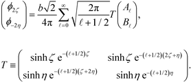 | (18) |
Once the coefficients A![[small script l]](https://www.rsc.org/images/entities/i_char_e146.gif) and B
and B![[small script l]](https://www.rsc.org/images/entities/i_char_e146.gif) have been solved, the polarization energy can be calculated by using:
have been solved, the polarization energy can be calculated by using:
 | (19) |
By writing coefficients A![[small script l]](https://www.rsc.org/images/entities/i_char_e146.gif) and B
and B![[small script l]](https://www.rsc.org/images/entities/i_char_e146.gif) explicitly in terms of charges Qζ and Qη, the elastance coefficients can be obtained from the summation of entries in array T.
explicitly in terms of charges Qζ and Qη, the elastance coefficients can be obtained from the summation of entries in array T.
3 Contact energy for symmetric charges
To demonstrate the application of eqn (14), (15), (18) and (19), we first compare the charge densities obtained from the above formalism to the known results for conducting spheres.3 The expressions in ref. 3 were derived by employing the facts that conducting spheres have a constant potential, which is inapplicable for dielectric spheres. However, within our formalism, the behavior of conducting spheres can be recovered by setting the dielectric permittivity εout = ∞ or ε = 1. Setting ε = 1 first then inverting the coefficient array (I − CI)![[small script l]](https://www.rsc.org/images/entities/i_char_e146.gif)
![[small script l]](https://www.rsc.org/images/entities/i_char_e146.gif) ′ leads to a singular behavior. In practice, it is found that inverting the array for ε values approaching 1 results in converged charge densities. Fig. 2 shows that for separation R/a = 3, the values ε = 0.9 and ε = 0.99 both produce charge densities that are indistinguishable from those predicted using the expressions in ref. 3.
′ leads to a singular behavior. In practice, it is found that inverting the array for ε values approaching 1 results in converged charge densities. Fig. 2 shows that for separation R/a = 3, the values ε = 0.9 and ε = 0.99 both produce charge densities that are indistinguishable from those predicted using the expressions in ref. 3.
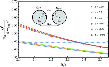
Then, the contact energy for dielectric spheres with symmetric charges can be calculated as follows. First, the interaction energy for a given dielectric permittivity, which includes the pairwise Coulomb energy and the mutual polarization energy, with the self-polarization energy omitted, is calculated at several separations, close to the contact value 2, which is the last term given by eqn (18) and (19). Then, the separation dependence is fitted and extrapolated to the close-contact value. This procedure is demonstrated in Fig. 3, for two spheres with identical radii and charges Q1 = Q2 = 1. Two families of data points are calculated from the cases with strong polarization, i.e., ε → ±1. In both cases, the fitting is based on quadratic polynomials, and a smooth extrapolation towards R/a = 2 can be made.
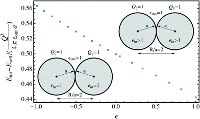
The extrapolated values for the contact energy are plotted against the values of ε in Fig. 4. Three limits are worth noting. (1) At ε = 0, the dielectric interface and polarization contribution vanishes. So the total energy is dominated by the normal Coulomb interaction, which is 0.5 on this normalized scale. (2) At ε = 1, the behavior approaches that of conducting spheres, as demonstrated in Fig. 2. The value for the contact energy obtained from the Maxwell expression (eqn (1)), which is 1/ln(2) − 1 ≃ 0.44, is recovered. (3) At ε = −1, the behavior of weak dielectrics, with εin ≪ εout, is recovered. This is the typical case for an aqueous solution of colloidal particles. In this limit, the polarization energy becomes independent of the internal dielectric permittivity, and is determined by the medium permittivity. From the known result13 for the electrostatic potential ϕw produced by a point charge outside dielectric particles with a low value of permittivity, the polarization energy can be estimated to be (1/2)(Q1ϕ1 + Q2ϕ2), in which ϕ1 and ϕ2 are the electrostatic potential ϕw produced by charges Q1 and Q2, and evaluated at the location of Q1 and Q2, which is a correction to the self-polarization energy. Taking the limit R/a = 2, it is straightforward to show that Q1ϕ1 = Q2ϕ2 = 1/3 + ln(3/4 = 0.05) on the normalized scale. Adding this value to the Coulomb energy gives an estimate of 0.55, a value very close to that obtained from the numerical approach.
4 Summary
The main result is shown in Fig. 4, displaying the contact energy for symmetric dielectric spheres at all dielectric permittivity values, which includes the weak dielectric and conducting spheres as the special cases. Physically, this contact energy is the work needed for bringing the two dielectric spheres into contact. We found that the work is mainly dominated by the normal Coulomb interactions , 0.5 in the reduced unit. The polarization correction is small for all possibilities, leading to at most ±10% of variation, which suggests that for most practical cases, the polarization correction for particles carrying the same amount of charges can be safely neglected.
The formalism developed, although only applied to spherical geometries, can be readily modified to treat the cases involving flat interfaces, by setting ζ = 0 or η = 0, or to charged cylinders, by modifying the metric hϕ related to the azimuthal degree of freedom. To adapt the formalism to arbitrary source charge distribution, the same type of multipole expansion can be applied, and eqn (13) is the most general form of constitutive equation. This formalism, however, only works for continuum media and breaks down when the inter-particle separation becomes comparable to the average separation between discrete charges on the surface. The dielectric permittivity of particles need not be identical, as is clearly shown by the expression for the boundary conditions. Further, the surface polarization can be induced by externally applied and oscillating fields, as demonstrated in ref. 12 in the treatment of van der Waals interactions.
The numerical data was only provided for the symmetric case. The contact energy for the asymmetric case such as Q1 = 1 and Q2 = −1 cannot be obtained by applying the extrapolation in Fig. 3, because the contact charge accumulates rapidly at small separations, which leads to a nearly singular behavior for the separation dependence of polarization energy, as demonstrated in ref. 4. For the conducting case, this leads to a  dependence. For the dielectric cases, this dependence is weakened; no analogous expression based on the Derjaguin approximation can be readily obtained, since the dielectrics are not equipotential. Yet, in the absence of an analytical expression for the strength of this singularity, any numerical extrapolation will fail at sufficiently small separation. We thus leave the clarification of this issue to future work.
Conflicts of interest
There are no conflicts to declare.Acknowledgements
J. Q. acknowledges support from the Terman Faculty Fund, the 3M Non-Tenured Faculty Award, and the Hellman Scholar Award. This research has been supported by the Assistant Secretary for Energy Efficiency and Renewable Energy, Office of Vehicle Technologies of the U.S. Department of Energy through the Advanced Battery Materials Research (BMR) Program (Battery500 Consortium).References
- J. Maxwell, A Treatise on Electricity and Magnetism, Clarendon Press, 1873 Search PubMed.
- A. Russell, Proc. Phys. Soc., London, 1922, 35, 10 CrossRef.
- J. Lekner, Proc. R. Soc. A, 2012, 468, 2829 CrossRef.
- J. Qin, N. W. Krapf and T. A. Witten, Phys. Rev. E, 2016, 93, 022603 CrossRef PubMed.
- K. Barros, D. Sinkovits and E. Luijten, J. Chem. Phys., 2014, 140, 64903 CrossRef PubMed.
- K. Barros and E. Luijten, Phys. Rev. Lett., 2014, 113, 1–5 CrossRef PubMed.
- Z. Gan, S. Jiang, E. Luijten and Z. Xu, SIAM J. Sci. Comput., 2016, 38, 375–395 CrossRef.
- J. Qin, J. J. de Pablo and K. F. Freed, J. Chem. Phys., 2016, 145, 124903 CrossRef PubMed.
- J. Qin, J. Li, V. Lee, H. Jaeger, J. J. de Pablo and K. F. Freed, J. Colloid Interface Sci., 2016, 469, 237–241 CrossRef CAS PubMed.
- K. Gustafson, G. Xu, K. F. Freed and J. Qin, J. Chem. Phys., 2017, 147, 064908 CrossRef PubMed.
- W. R. Smythe, Static and Dynamic Electricity, McGraw-Hill Book Company, Inc., 1950 Search PubMed.
- D. Mitchell and B. Ninham, J. Chem. Phys., 1972, 56, 1117–1126 CrossRef CAS.
- A. P. dos Santos, A. Bakhshandeh and Y. Levin, J. Chem. Phys., 2011, 135, 044124 CrossRef PubMed.
| This journal is © The Royal Society of Chemistry 2018 |

