Novel conjugated polymers based on bis-dithieno[3,2-b;2′,3′-d]pyrrole vinylene donor and diketopyrrolopyrrole acceptor: side chain engineering in organic field effect transistors†
Fang-Ju
Lin
ab,
Song-Di
Lin
a,
Chih-Hao
Chin
b,
Wei-Tsung
Chuang
*b and
Chain-Shu
Hsu
 *a
*a
aDepartment of Applied Chemistry, National Chiao Tung University, 1001 Ta-Hsueh Road, Hsinchu, 30029, Taiwan. E-mail: cshsu@nctu.edu.tw
bNational Synchrotron Radiation Research Center, 101 Hsin-Ann Road, Hsinchu, 30076, Taiwan
First published on 17th November 2017
Abstract
Two new donor–acceptor conjugated polymers, i.e. PB(C12DTP)V-DTDPP-C12 and PB(C12DTP)V-DTDPP-C12C8, were prepared by the Stille coupling of (E)-1,2-bis(4-dodecyl-6-(trimethylstannyl)-4H-dithieno[3,2-b:2′,3′-d]pyrrol-2-yl)ethene (Sn-B(C12DTP)V) with 3,6-bis(5-bromothiophen-2-yl)-2,5-didodecylpyrrolo[3,4-c]pyrrole-1,4-dione (Br-DTDPP-C12) and 3,6-bis(5-bromo-thiophen-2-yl)-2,5-bis(2-octyldodecyl)pyrrolo[3,4-c]pyrrole-1,4-dione (Br-DTDPP-C8C12), respectively. The molecular weight and thermal properties of the obtained polymers were characterized by gel permeation chromatography (GPC), differential scanning calorimetry (DSC) and thermogravimetry (TG). Their optical and electrochemical properties were analyzed by UV-vis-NIR spectroscopy and cyclic voltammetry (CV). The morphological and molecular-packing features of the polymers were characterized by optical microscopy and atomic force microscopy (AFM), UV polarization spectroscopy and grazing incidence X-ray diffraction (GIXD) to determine the relationship between the structural morphology and the performance. PB(C12DTP)V-DTDPP-C12C8 with branched C12C8 side chains on DPP units shows much higher hole mobility (1.2 cm2 V−1 s−1) than 0.69 cm2 V−1 s−1 of PB(C12DTP)V-DTDPP-C12.
Introduction
Donor–acceptor (D–A) conjugated copolymers have attracted extensive scientific research interest because of their promising applications in organic field effect transistors (OFETs),1 organic solar cells,2 light-emitting diodes3 and memory devices.4 In developing high-performance OFET D–A polymers, manipulating the D and A configuration is a most common strategy to improve the length of intramolecular effective conjugation, the coplanarity of the backbone, the intermolecular π–π stacking order, the energy level and the band gap.1,5Highly planar D–A polymers providing sufficient intramolecular π conjugation and tight intermolecular π–π stacking could be advantageous for intra- and inter-chain charge transport over poly(3-hexylthiophene-2,5-diyl) (P3HT) with a high degree of crystallinity.5,6 The design of the coplanarity in the D–A backbones hence becomes particularly important.1 In preceding work, highly planar diketopyrrolopyrrole (DPP), naphthalene diimide (NDI), and isoindigo (IID) were incorporated into D–A copolymers mostly as the acceptor units, but the coplanarity of the entire backbone was decreased by torsionable linkages generated on inducing the thiophene donors.7–9 Recent research efforts have, therefore, focused on improving the inter-annular rotation and the torsion angle of the D–A backbone.10–15 Our laboratories demonstrated an induced multifused structure, including tricyclic and tetracyclic arenes, on DPP-based backbones to avoid the inter-annular rotation of the backbones.11,12 Moreover, using a vinylene linkage between two thiophene donors can reconcile the torsion angle of the backbones, resulting in highly coplanar conjugated structures and a superior OFET performance.10,13–15
Flexible side chains play a compensating role in the fine adjustment of not only the solubility of the copolymers in organic solvents during solution processes but also the intermolecular packing of the rigid backbone during dewetting processes.16–19 Many side-chain engineering approaches, e.g. types,20 lengths,21 appended position22 and grafted densities,23 have thus become a significant issue in improving the electro-optic properties of the conjugated copolymers. Kang et al. demonstrated that moving the branching position of alkyl side chains away from the DPP unit of poly(selenophene-vinylene-selenophene-diketopyrrolopyrrole) (PSVS-DPP) backbones sufficiently decreased the steric hindrance of the side chains, increased the π–π interactions, adjusted the distance of the vertically adjacent layer and promoted long-range order.24 Lee et al. reported that a branched side chain on the benzotriazole (BTz) unit of thienylene-vinylene-thienylene-benzotriazole polymers (PTVT-BTz) promoted the formation of a backbone structure more tilted than a linear side chain, resulting in an improved overlap of π-electron densities and high hole mobility.23 These conditions signify that selecting suitable side chains is as critical as the D–A backbone for the design of next-generation D–A copolymers, but the effect of the side chains on the intra- and interlayer packing stability of backbones in thin films of D–A polymers is unclear.19
In this study, we synthesized two new D–A type conjugated polymers, composed of an extended bis-dithieno[3,2-b:2′,3′-d]pyrrole (DTP) vinylene and dithiophene tethered DPP units. In this molecular design of donor units, extending two DTP molecules linked by the vinylene group can maintain the backbone coplanarity and a small band gap, but might also result in instability of the inter- or intra-chain packing and insolubility. To probe efficient meso-structures for high-performance OFET devices,5,16 we, therefore, designed branched alkyl chains symmetrically grafted on the DPP units of the B(DTP)V-DTDPP backbone, named PB(C12DTP)V-DTDPP-C12C8, in addition to common linear alkyl chains for PB(C12DTP)V-DTDPP-C12. We contend that the long and rigid backbone of D–A polymers with the matching side-chain topology renders a new route for the molecular design of π-conjugated polymers to improve the OFET performance.
Experimental
Materials
All chemicals were purchased from Aldrich, Tokyo Chemical Industry (TCI), and Acros, and used as received unless otherwise specified. Monomers, N-dodecyl dithieno[3,2-b:2′,3′-d]pyrrole, 2,5-bis-(2-octyldodecyl)-3,6-dithiophen-2-yl-pyrrolo[3,4-c]pyrrole-1,4-dione (DTDPP-C12C8) and 2,5-didodecyl-3,6-dithiophen-2-yl-pyrrolo[3,4-c]pyrrole-1,4-dione (DTDPP-C12) were prepared according to literature methods.25,26![[thin space (1/6-em)]](https://www.rsc.org/images/entities/char_2009.gif) :
:![[thin space (1/6-em)]](https://www.rsc.org/images/entities/char_2009.gif) 1) to give the final compound, C12-DTP-CHO, as a yellow liquid (2.80 g, 86%). 1H NMR (400 MHz, CDCl3): δ 9.88 (s, 1H), 7.65 (s, 1H), 7.38 (d, J = 5.6 Hz, 1H), 7.02 (d, J = 5.6 Hz, 1H), 4.23 (t, J = 6.8 Hz, 2H), 1.89 (m, 2H), 1.31 (m, 21H),0.86 (t, J = 6.8 Hz, 3H) ppm.
1) to give the final compound, C12-DTP-CHO, as a yellow liquid (2.80 g, 86%). 1H NMR (400 MHz, CDCl3): δ 9.88 (s, 1H), 7.65 (s, 1H), 7.38 (d, J = 5.6 Hz, 1H), 7.02 (d, J = 5.6 Hz, 1H), 4.23 (t, J = 6.8 Hz, 2H), 1.89 (m, 2H), 1.31 (m, 21H),0.86 (t, J = 6.8 Hz, 3H) ppm.
![[thin space (1/6-em)]](https://www.rsc.org/images/entities/char_2009.gif) :
:![[thin space (1/6-em)]](https://www.rsc.org/images/entities/char_2009.gif) 3) to give the final compound, B(C12DTP)V, as an orange solid (1.00 g, 37%) with a Tm of 87 °C. 1H NMR (400 MHz, CDCl3): δ 7.12 (d, J = 5.2 Hz, 2H), 7.06 (s, 2H), 6.97 (d, J = 4.4 Hz, 2H), 6.93 (s, 2H), 4.15 (t, J = 6.8 Hz, 4H), 1.85 (m, 4H), 1.27 (m, 42H), 0.87 (t, J = 6.8 Hz, 6H) ppm. 13C NMR (CDCl3): δ 145.2, 144.7, 140.5, 127.5, 124.0, 117.9, 115.1, 110.5, 109.8, 47.3, 32.0, 30.3, 29.6, 29.5, 27.0, 22.7, 14.1 ppm. Mass (m/z): 718, 359.
3) to give the final compound, B(C12DTP)V, as an orange solid (1.00 g, 37%) with a Tm of 87 °C. 1H NMR (400 MHz, CDCl3): δ 7.12 (d, J = 5.2 Hz, 2H), 7.06 (s, 2H), 6.97 (d, J = 4.4 Hz, 2H), 6.93 (s, 2H), 4.15 (t, J = 6.8 Hz, 4H), 1.85 (m, 4H), 1.27 (m, 42H), 0.87 (t, J = 6.8 Hz, 6H) ppm. 13C NMR (CDCl3): δ 145.2, 144.7, 140.5, 127.5, 124.0, 117.9, 115.1, 110.5, 109.8, 47.3, 32.0, 30.3, 29.6, 29.5, 27.0, 22.7, 14.1 ppm. Mass (m/z): 718, 359.
OFET fabrication and characterization of polymer thin films
OFETs were fabricated on highly doped silicon substrates with a bottom-gate top-contact structure. A SiO2 layer (thickness 300 nm) was deposited on silicon substrates and it served as a gate dielectric. The SiO2 surface was modified with octadecyltrichlorosilane (ODTS). The PB(C12DTP)V-DTDPP-C12 and PB(C12DTP)V-DTDPP-C12C8 solutions were prepared at a concentration of 10 mg mL−1 in chlorobenzene (CB) or 1,2-dichlorobenzene (ODCB). The highly aligned polymer films (thickness ∼40 nm) were fabricated with the off-center spin-coating (OCSC) method,27,28 in which the polymer solution was injected 3 cm away from the center of the spin-coater at a spin rate of 2000 or 2500 rpm under nitrogen. The thin-films were annealed at various temperatures (50, 180, 200 and 220 °C) for 10 min under nitrogen. Subsequently, gold electrodes as the source and drain electrodes were thermally evaporated onto the polymer thin films through a shadow mask. The source-to-drain direction was parallel to the aligning direction of the polymer chains. The OFET performances were measured by using an Agilent B1500 series parametric analyzer. The hole mobilities (μhs) were calculated from the data in the saturation regime with the equation:| μ = (2IDSL)/(WC(VG − Vth)2) |
Instrumentation and theoretical calculations
Nuclear magnetic resonance (NMR) spectra were recorded (Varian Unity-300 and Agilent Unity-400 spectrometers) with samples in deuterated dichloromethane solution near 23 °C. The chemical shifts of signals in these spectra were recorded in ppm. Coupling parameters (J) were obtained in hertz. The resonance multiplicity is described as s (singlet), d (doublet), t (triplet), and m (multiplet). The molar mass (Mn) and polydispersity index (PDI) were obtained at 25 °C by gel permeation chromatography (GPC) (polystyrene standards; eluent: 1,2-dichlorobenzene). Thermogravimetric analysis (PerkinElmer model Pyris 1 TGA) and differential scanning calorimetry (DSC) measurements (TA Instruments DSC Q200) were performed under a nitrogen flow of 50 mL min−1 at a scan rate of 10 °C min−1. UV-vis-NIR spectra were obtained by using a Hitachi U-4100 spectrophotometer. Geometry optimizations and normal-mode calculations were performed at the B3LYP/6-311G(d,p) and PCM model (chloroform, ε = 4.71; 1,2 dichlorobenzene, ε = 9.99) using the Gaussian 09. Electrochemistry measurements (CH Instruments model 61 ID) were performed near 23 °C in a classical three-electrode cell; the working, reference and counter electrodes were a glassy carbon electrode with polymer films, Ag/AgCl/CH3CN/(nC4H9)4NPF6 and a Pt wire, respectively. For calibration, the redox potential of ferrocene/ferrocenium (Fc/Fc+), measured under the same conditions, was located at 0.09 eV vs. the Ag/AgCl electrode; the redox potential of Fc/Fc+ has an absolute energy level of −4.80 eV to vacuum. The HOMO and LUMO energy levels were then calculated according to equations,| EHOMO = −(φox − φox(ferrocene) + 4.80) (eV) |
| EHOMO = −(φre − φre(ferrocene) + 4.80) (eV) |
Lc = 0.9λ/(βhkl![[thin space (1/6-em)]](https://www.rsc.org/images/entities/char_2009.gif) cos(θ)) cos(θ)) |
Results and discussion
Molecular design, synthesis and characterization
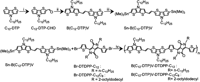
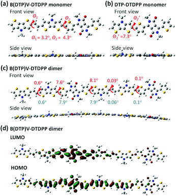
Scheme 1 outlines the synthetic procedure for the PB(DTP)V-DTDPP based polymers. Both PB(C12DTP)V-DTDPP-C12 and PB(C12DTP)V-DTDPP-C12C8 were prepared by a Stille coupling of (Sn-B(C12DTP)V) with Br-DTDPP-C12 and Br-DTDPP-C8C12, respectively. The obtained polymers were Soxhlet extracted with acetone and hexane to remove their small molar mass portion. The structure and purity of each molecule were evaluated with 1H NMR spectra and mass spectra, as shown in Fig. S1–S3.† The molar mass (Mn) and polydispersity index (PDI) were controlled at 38 kDa and 2.2 for PB(C12DTP)V-DTDPP-C12 and 16 kDa and 1.3 for PB(C12DTP)V-DTDPP-C12C8, respectively. The decomposition temperatures of both copolymers are ca. 365 and 342 °C, respectively (Fig. S4†). The copolymers were heated up to 320 °C to avoid thermal degradation in the DSC analysis (Fig. S5†). Phase transition was not obviously found for both polymers below 320 °C, which indicated that the melting point of both polymers should be very close to their decomposition temperature. Both polymers displayed good solubilities in chloroform, chlorobenzene and 1,2-dichlorobenzene. Solutions with concentrations of 2 mg mL−1 and 10 mg mL−1 were respectively prepared at room temperature and 60 °C. The solutions prepared at room temperature and 60 °C were able to pass through a 0.45 μm pore size PTFE filter. Hence, chloroform, chlorobenzene and 1,2-dichlorobenzene were used as solvents in the experiments.For further understanding the theoretical planarity of the synthesized polymers, Fig. 1 shows the conformational simulation of the designed DTP-based conjugated backbones by density functional theory (DFT). Although the conformational defects of conjugated polymers in the bulk state are difficult to obtain exactly from the DFT calculation, the DFT simulation can provide a reference of theoretical planarity for revealing the relationship between the molecular design of the synthesized polymers and the OFET device performance. The optimized structures were obtained using the B3LYP/6-311G(d,p) and PCM model (chloroform, ε = 4.71; 1,2 dichlorobenzene, ε = 9.99) in the Gaussian 09 package.
In the B(DTP)V-DTDPP monomer (Fig. 1a), the linkage between the DTP unit and the vinyl group shows a dihedral angle θ1 of about 3.2°. Notably, the two DTP units linked with the vinyl group greatly decrease the dihedral angle θ2 between DTP and thiophene (4.3°) relative to an angle of 7.3° in the single DTP and thiophene case34 (as shown in Fig. 1b). From the side view the monomer backbone of B(DTP)V-DTDPP evidently exhibits great planarity. As shown in Fig. 1c, a dimer of B(DTP)V-DTDPP displays a small angle, ca. 8.1°, between two repeating units, indicating that the polymers can maintain small steric hindrance between the intramolecular units and remain planar. In Fig. 1d, the electron densities of the HOMO and LUMO are well delocalized over the conjugated repeat units of the PB(DTP)V-DTDPP backbones. The coplanarity and delocalized electronic structure of the B(DTP)V-DTDTPP backbone might correspond to a requirement of fabricating highly efficient OFET D–A polymers.
Optical and electrochemical properties
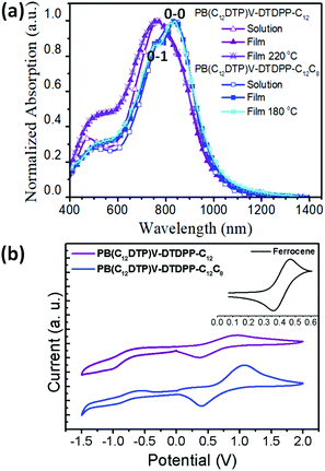
Fig. 2a shows that the normalized UV-vis-NIR spectra exhibit broad dual-band absorptions in the region of 400–1200 nm for the two cases in both solution (in chloroform) and thin film states. The absorption features at high and low energies are attributed to a π–π* transition and intramolecular charge transfer (ICT) between DTP and DPP segments, respectively.10,35 Relative to the solution state, the broader absorption bands in the film state result from aggregation or orderly π–π stacking, which is helpful to improve the charge transport of devices.35 Interestingly, compared to the λmax of PB(C12DTP)V-DTDPP-C12C8, the absorption of PB(C12DTP)V-DTDPP-C12 blue-shifted by 80 nm, which suggested the increase in H-aggregation.10,21,36 The 0-1 vibration peak is observed in the PB(C12DTP)V-DTDPP-C12C8 film and the 0-0/0-1 c ratio for the PB(C12DTP)V-DTDPP-C12C8 film is larger than the unity, which manifests the existence of stronger intrachain interactions or J-aggregation during solidification and annealing.20,36 Both polymers featuring identical conjugated backbones, therefore, display similar optical energy bandgaps (Eoptg), −1.23 and −1.24 eV, estimated from the absorption onsets at a long wavelength, for PB(C12DTP)V-DTDPP-C12C8 and PB(C12DTP)V-DTDPP-C12, respectively (Table 1). In Fig. 2b, the cyclic voltammograms reveal that the highest occupied molecular orbital (HOMO)/lowest unoccupied molecular orbital (LUMO) levels are −4.83/−3.53 eV for PB(C12DTP)V-DTDPP-C12 and −4.97/−3.58 eV for PB(C12DTP)V-DTDPP-C12C8.| Polymers |
λ
solmax![[thin space (1/6-em)]](https://www.rsc.org/images/entities/char_2009.gif) a (nm) a (nm) |
λ
filmmax![[thin space (1/6-em)]](https://www.rsc.org/images/entities/char_2009.gif) b (nm) b (nm) |
E
optg![[thin space (1/6-em)]](https://www.rsc.org/images/entities/char_2009.gif) c (eV) c (eV) |
E
HOMO/ELUMO![[thin space (1/6-em)]](https://www.rsc.org/images/entities/char_2009.gif) d (eV) d (eV) |
E
elecg![[thin space (1/6-em)]](https://www.rsc.org/images/entities/char_2009.gif) e (eV) e (eV) |
|---|---|---|---|---|---|
| a Solution absorption spectra (10−5 M in trichloromethane). b Thin-film absorption spectra from films spin-cast from TCE solution (5 mg mL−1). c Optical energy gap estimated from the onset of film absorption. d Cyclic voltammograms were recorded with Fc/Fc+ (EHOMO = −4.8 eV) as the external reference. e E elecg = ELUMO − EHOMO. | |||||
| PB(DTP)V-DTDPP-C12 | 765 | 762 | 1.24 | −4.83/−3.53 | 1.30 |
| PB(DTP)V-DTDPP-C12C8 | 841 | 845 | 1.23 | −4.97/−3.58 | 1.39 |
Fabrication of OFET and I–V characterization
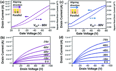
In order to evaluate the clear side chain impact on the intra- and inter-molecular charge transport, off-center spin-coating (OCSC)27,28 was used to align the polymer chains to form a highly orientated polymer thin film. The OCSC PB(DTP)V-DTDPP devices were fabricated in a bottom-gate top-contact (BGTC) configuration, where the source–drain axis was parallel to the polymer chains’ alignment. The fabrication process is described in the Experimental section. After experiments with various solvents, spin rates, and annealing temperatures (Table 2 and Table S1†), the best device performance was found at an annealing temperature of 220 °C for PB(C12DTP)V-DTDPP-C12 and at 180 °C for PB(C12DTP)V-DTDPP-C12C8. 1,2-Dichlorobenzene is a better solvent for both polymers compared to chlorobenzene. The OCSC device performance mainly contributed to the intramolecular charge transport behavior of polymer chains. Both the best transfer and output characteristics of PB(C12DTP)V-DTDPP-C12 and PB(C12DTP)V-DTDPP-C12C8 devices are depicted in Fig. 3; the hole mobility (μh), threshold voltage (Vth) and on/off current ratios (Ion/Ioff) are summarized in Table 2. The saturation-regime mobilities were calculated from the slope of a plot of the square root of the drain current (IDS−0.5) as a function of gate voltage (VG). Small Ion/Ioff values result from the ionization energies of the two polymers.8,37 The maximum μh attained is 0.69 cm2 V−1 s−1 for PB(C12DTP)V-DTDPP-C12 devices and 1.2 cm2 V−1 s−1 for PB(C12DTP)V-DTDPP-C12C8 devices. The average μh of the PB(C12DTP)V-DTDPP-C12C8 device was calculated to be 1.0 cm2 V−1 s−1, which is twice that of a PB(C12DTP)V-DTDPP-C12 device (0.52 cm2 V−1 s−1). The PB(C12DTP)V-DTDPP-C12C8 devices had 3 times higher mobility than the PDTP-DTDPP polymers bearing only one DTP unit reported in the literature.18 As the polymer chains were perpendicular to the source–drain axis, the performances of the OFET devices drastically decreased (Table 2). Compared with OCSC films, the spin-coated (SC) films exhibited a smaller μh, 0.061 cm2 V−1 s−1, for the PB(C12DTP)V-DTDPP-C12 device and 0.11 cm2 V−1 s−1 for the PB(C12DTP)V-DTDPP-C12C8 device, which resulted from the combined effect of intra-/inter-molecular charge transport and possible defects. The excellent OCSC device performance of PB(C12DTP)V-DTDPP-C12C8 indicates its superior intramolecular charge transport property and corresponds to the results of UV-visible-NIR spectroscopy (Fig. 2a).| Polymers | Coating method | Coating direction |
T
a![[thin space (1/6-em)]](https://www.rsc.org/images/entities/char_2009.gif) a (°C) a (°C) |
μ h, adv(μh, max)b (cm2 V−1 s−1) |
V
th![[thin space (1/6-em)]](https://www.rsc.org/images/entities/char_2009.gif) c (V) c (V) |
I on/Ioff |
|---|---|---|---|---|---|---|
| a T a indicates the annealing temperature. b Average mobilities and maximum values of hole mobility are shown in parentheses (more than 30 devices were tested for each polymer). c Averaged value of 30 devices. SC indicates spin-coating. All thin films were prepared using ODCB solvent at a spin rate of 2000 rpm. | ||||||
| PB(DTP)V-DTDPP-C12 | OCSC | Parallel | 180 | 0.10(0.21) | −33 | 101–102 |
| OCSC | Parallel | 200 | 0.27(0.35) | −28 | 101–102 | |
| OCSC | Parallel | 220 | 0.52(0.69) | −27 | 101–102 | |
| OCSC | Vertical | 220 | 0.008(0.012) | −27 | 101–102 | |
| SC | — | 220 | 0.037(0.061) | −22 | 101–102 | |
| PB(DTP)V-DTDPP-C12C8 | OCSC | Parallel | 180 | 1.0(1.2) | −19 | 101–102 |
| OCSC | Vertical | 180 | 0.032(0.036) | −23 | 101–102 | |
| OCSC | Parallel | 200 | 0.53(0.75) | −20 | 101–102 | |
| OCSC | Parallel | 220 | 0.12(0.43) | −24 | 101–102 | |
| SC | — | 180 | 0.062(0.11) | −25 | 101–102 | |
Chain alignment of OCSC films
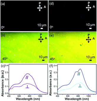
Fig. 4a, b, d and e show images, obtained using a polarized optical microscope (POM), of two polymer OCSC thin films. The brightest images are observed only when the aligning direction of the films is tilted 45° to either the polarizer or analyzer. This condition indicates that, with the OCSC process, the backbones are oriented mostly along the alignment direction.6,28,38 To quantify the degree of alignment, we derived the optical dichroic ratio D = A∥/A⊥ from the polarized UV spectra (Fig. 4c and f); A∥ and A⊥ denote the absorbance maximum of a vibrational signal in polarized and depolarized UV curves respectively.6 The PB(C12DTP)V-DTDPP-C12C8 exhibits a larger dichroic ratio (D = 2.18) than PB(C12DTP)V-DTDPP-C12 (D = 1.97), revealing that the designed branched side chains can support a greater degree of chain alignment.Surface topology of OCSC films
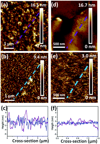
Surface roughness has been demonstrated to affect the OFET performance in some conjugated copolymers.6,10,37 In Fig. 5, AFM height images reveal the surface topographies of the optimal devices for realizing the roughness of PB(C12DTP)V-DTDPP-C12 and PB(C12DTP)V-DTDPP-C12C8 films relative to their device performance. Their phase images exhibit fiber-like textures (domain size, a few hundred nm) as shown in Fig. S6.† The thickness of the OCSC polymer thin films is about 40 nm. Roughness parameters (Rt) of the top surface of the films, estimated from the full area of the AFM height images, are 1.89 and 0.44 nm for the PB(C12DTP)V-DTDPP-C12 and PB(C12DTP)V-DTDPP-C12C8 devices, respectively. Roughness parameters (Rb) of the bottom surface were obtained from both the films peeled off the substrate of the optimal devices as shown in the AFM height images (Fig. 5d and e). The Rb is 1.13 nm for the PB(C12DTP)V-DTDPP-C12 film and 0.44 nm for the PB(C12DTP)V-DTDPP-C12C8 film.The statistical roughness parameters and 1D height profiles extracted arbitrarily from the AFM height images (Fig. 5c and f) obviously reveal that the PB(C12DTP)V-DTDPP-C12C8 has a smaller roughness value than the PB(C12DTP)V-DTDPP-C12. We also found the same result from the device fabricated using different solvents and spin rates (Fig. S7†). The smaller top and bottom surface roughness parameters of the PB(C12DTP)V-DTDPP-C12C8 film mean that the thin film is much smoother and fits on the substrate. The smoother interface between the semiconductor and dielectric layers on bottom-gate top-contact (BGTC) devices decreases the opportunity of charge trapping, as a result PB(C12DTP)V-DTDPP-C12C8 films exhibit higher charge transport.6,10,37 Higher surface roughness in PB(C12DTP)V-DTDPP-C12 may be attributed to the nature of the materials, e.g. the thermal expansion coefficient, or larger stress relaxation after the thermal annealing.
Side-chain effect on mesostructures
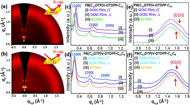
To determine the characteristics of the molecular packing and the degree of packing order in the microstructures of the PB(DTP)V-DTDPP films, we performed grazing incidence X-ray diffraction (GIXD) with the incident X-ray beam respectively parallel and perpendicular to the aligning direction of the optimal OCSC devices, as shown in Fig. 6 and S8.† The GIXD patterns exhibit lamellar-like diffractions, e.g. (100), (200) and (300), along the out-of-plane direction for the two cases of the PB(DTP)V-DTDPP polymers (Fig. 6c and d). As shown in Table 3, the lamellar thickness (d100 = 2.03 nm) for the PB(C12DTP)V-DTDPP-C12C8 OCSC film larger than that for the PB(C12DTP)V-DTDPP-C12 case (d100 = 1.85 nm) can be ascribed to the steric bulk of the branched C12C8 side chains. The isotropic scattering halo represents the mean distance between liquid-like alkyl side chains. The (010) diffraction corresponding to the π–π stacking distance emerged along the in-plane direction and partly overlapped with the isotropic halo, attributed to disordered alkyl side chains, when the incident X-ray beam was parallel to the aligning direction of the OCSC films (Fig. 6e and f), but weakened when the incident X-ray beam was perpendicular to the aligning direction of the OCSC films (Fig. 6e, f, S6a and b†) in the two cases. This result indicates that, with the OCSC process, the backbones displayed high orientation along the aligning direction. The lamellar thickness (d100) is smaller than the lateral dimension of the backbones with extended side chains (3.8 nm), indicating that the inter-digitation of the alkyl side chains might emerge within the lamellae. The π–π stacking distance, estimated from the Gaussian fitting peak, of PB(C12DTP)V-DTDPP-C12 is shorter than that of PB(C12DTP)V-DTDPP-C12C8 (Fig. S9,†Table 3). According to the peak width δb of the (100) diffraction calculated with the Scherrer equation,29–33,39 the grain size (Lc) of PB(C12DTP)V-DTDPP-C12C8 (20.2 nm) is 3.2 nm smaller than that of PB(C12DTP)V-DTDPP-C12, although the former has greater mobility (as manifested in Fig. 3). This result is in contrast to a common conclusion that a small grain size might produce a large grain boundary resulting in many traps or barriers to slow down the charge transport. Notably, sharp diffractions at (100), (200) and (300) but weak (010) diffraction in the two cases indicate the paracrystalline nature of the backbone packing existing within the highly aligned lamellae.29–33 The packing order of backbones within each layer is thus expected to become a decisive factor in charge transport.| Polymers | Coating method | d (100) (Å) |
d
(010)![[thin space (1/6-em)]](https://www.rsc.org/images/entities/char_2009.gif) a (Å) a (Å) |
L p(h00) (Å) |
![[N with combining macron]](https://www.rsc.org/images/entities/i_char_004e_0304.gif) (h00)b (h00)b |
g (h00) (%) |
|---|---|---|---|---|---|---|
a π–π stacking distance estimated from the Gaussian fitting peak.
b Average number of the diffraction planes, calculated from Lp = ![[N with combining macron]](https://www.rsc.org/images/entities/i_char_004e_0304.gif) d.
c Paracrystalline distortion parameter of the (h00) plane. SC indicates spin-coating. d.
c Paracrystalline distortion parameter of the (h00) plane. SC indicates spin-coating.
|
||||||
| PB(DTP)V-DTDPP-C12 | OCSC | 18.5 | 3.8 | 226.2 | 12.3 | 4.4 |
| SC | 20.5 | 4.0 | — | — | — | |
| PB(DTP)V-DTDPP-C12C8 | OCSC | 20.3 | 4.0 | 182.8 | 9.0 | 3.9 |
| SC | 20.4 | 4.0 | — | — | — | |
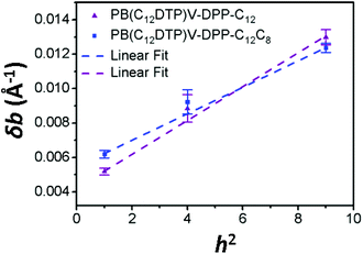
For paracrystalline systems, the distortion parameter (g) of paracrystals is determined from the slope (= g2π2/d) of the δb–h2 plot, in which a larger g value means more highly distorted paracrystals.29–33 The true paracrystalline size (Lp) can be obtained from the intercept with a linear extrapolation to h = 0; d and h are the lamellar thickness and the order of diffraction, respectively. Fig. 7 shows the δb–h2 plot extracted from the GIXD data of the two cases. The resultant paracrystalline parameters are listed in Table 3. The distortion parameter of PB(C12DTP)V-DTDPP-C12C8 (g = 3.9) is smaller than that (g = 4.4) of PB(C12DTP)V-DTDPP-C12, revealing that high packing distortion of the backbones exists in the lamellar structure of PB(C12DTP)V-DTDPP-C12.
An order parameter obtained from the dichroic ratio is also related to the packing order of backbones within the lamellae. Based on the assumption of an optical dipole moment parallel to the copolymer backbone, the 2D structural-order parameter Φ can be expressed in terms of the dichroic ratio as Φ = (D − 1)/(D + 1).38 The Φ value is between 0 and 1, corresponding to the isotropic orientation to the perfect uniaxial orientation. The order parameter of the PB(C12DTP)V-DTDPP-C12C8 film (Φ = 0.37) is greater than that of the PB(C12DTP)V-DTDPP-C12 film (Φ = 0.32). This result, consistent with the distortion parameter g, indicates that PB(C12DTP)V-DTDPP-C12C8 features a high packing order of backbones within the layers. Furthermore, the deviation of the lamellar thickness (d100) and backbone stacking distance (d010) values arises from the different film-forming processes in the linear C12 side chain case, whereas both values are constant for the OCSC and spin-coating processes in the branched C12C8 side chain case (Fig. 6 and S6,†Table 3).
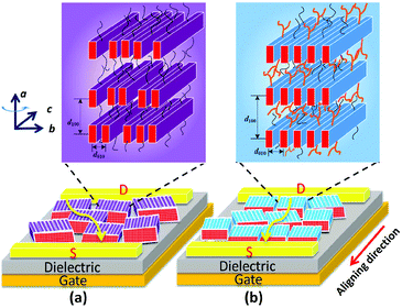
The above-mentioned results for the side-chain effect, featuring steric confinement and increased side-chain density, strongly indicate that the branched C12C8 side chains maintain the backbone coplanarity and act like latches between crystalline layers to stabilize the lamellar packing of the bulky backbones. Nevertheless, the flexible linear C12 side chains cause a slight twist in the backbone and lack steric hindrance, resulting in a dynamic variability of intra- and inter-chain distances. Although the thin films of PB(C12DTP)V-DTDPP-C12 show a larger grain size, as illustrated in Fig. 8, the packing order of their backbones within the lamellae might strongly influence their charge transport, even with just a small difference between the meso-structures in the bulky backbone system. We therefore suggest that appropriate side chains play a key role in maintaining the backbone coplanarity and stabilizing the packing order of bulky backbones and their charge-transport characteristics.
Conclusions
Two PB(DTP)V-DTDPP based conjugated polymers with linear C12 and branched C12C8 side chains were prepared and characterized. Both polymers show strong absorption in the 600–1000 nm region. An off-center spin-coating method was used to fabricate the polymer thin films and OFET devices. Strong anisotropy for the polymer thin film was observed in polarized optical microscopy and polarized UV spectroscopy. The OFET results demonstrate that the π-extended PB(DTP)V-DTDPP polymers displayed a hole mobility 3 times higher than that of the PDTP-DTDPP polymers bearing only one DTP unit reported in the literature. The PB(DTP)V-DTDPP with branched C12C8 side chains exhibits a maximum hole mobility of 1.2 cm2 V−1 s−1, which is about twice that of the linear C12 side-chain case (0.69 cm2 V−1 s−1). This improved performance is attributed to the branched C12C8 side chains, causing steric hindrance, that can maintain the backbone coplanarity and act like latches between crystalline layers to efficiently stabilize the π–π stacking of backbones and the 2D packing order of the paracrystalline structure. For a long conjugated polymer backbone, we suggest that a rigid backbone with matching side-chain density is necessary to adjust the stacking order within the layer for an impressive OFET performance.Conflicts of interest
There are no conflicts to declare.Acknowledgements
The Ministry of Science and Technology of Taiwan, ROC (MOST 101-2221-E009-026) provided financial support.References
- Y. Yao, H. Dong and W. Hu, Adv. Mater., 2016, 28, 4513–4523 CrossRef CAS PubMed.
- J.-S. Wu, S.-W. Cheng, Y.-J. Cheng and C.-S. Hsu, Chem. Soc. Rev., 2015, 44, 1113–1154 RSC.
- J. Yu, H. Tan, F. Meng, K. Lv, W. Zhu and S. Su, Dyes Pigm., 2016, 131, 231–238 CrossRef CAS.
- T.-T. Huang, C.-L. Tsai, S.-H. Hsiao and G.-S. Liou, RSC Adv., 2016, 6, 28815–28819 RSC.
- S. Himmelberger and A. Salleo, MRS Commun., 2015, 5, 383–395 CrossRef CAS.
- F.-J. Lin, C. Guo, W.-T. Chuang, C.-L. Wang, Q. Wang, H. Liu, C.-S. Hsu and L. Jiang, Adv. Mater., 2017, 29, 1606987 CrossRef PubMed.
- H. Sun, Q. Wang, J. Qian, Y. Yin, Y. Shi and Y. Li, Semicond. Sci. Technol., 2015, 30, 054001 CrossRef.
- P. Bujak, I. Kulszewicz-Bajer, M. Zagorska, V. Maurel, I. Wielgus and A. Pron, Chem. Soc. Rev., 2013, 42, 8895–8999 RSC.
- Z. Yi, S. Wang and Y. Liu, Adv. Mater., 2015, 27, 3589–3606 CrossRef CAS PubMed.
- K.-Y. Wu, C.-C. Chiu, W.-T. Chuang, C.-L. Wang and C.-S. Hsu, Polym. Chem., 2015, 6, 1309–1315 RSC.
- Y.-C. Pao, C.-T. Yang, Y.-Y. Lai, W.-C. Huang, C.-S. Hsu and Y.-J. Cheng, Polym. Chem., 2016, 7, 4654–4660 RSC.
- C.-E. Tsai, R. H. Yu, F.-J. Lin, Y.-Y. Lai, J.-Y. Hsu, S.-W. Cheng, C.-S. Hsu and Y.-J. Cheng, Chem. Mater., 2016, 28, 5121–5130 CrossRef CAS.
- W. Zhang and G. Yu, J. Polym. Sci., Part A: Polym. Chem., 2017, 55, 585–603 CrossRef CAS.
- F. Liu, C. Wang, J. K. Baral, L. Zhang, J. J. Watkins, A. L. Briseno and T. P. Russell, J. Am. Chem. Soc., 2013, 135, 19248–19259 CrossRef CAS PubMed.
- H. Chen, Y. Guo, G. Yu, Y. Zhao, J. Zhang, D. Gao, H. Liu and Y. Liu, Adv. Mater., 2012, 24, 4618–4622 CrossRef CAS PubMed.
- C. Dong, H. Hoppe and W. J. D. Beenken, J. Phys. Chem. A, 2016, 120, 3835–3841 CrossRef CAS PubMed.
- K. Ogawa, J. A. Stafford, S. D. Rothstein, D. E. Tallman and D. C. Rasmussen, Synth. Met., 2005, 152, 137–140 CrossRef CAS.
- T. L. Nelson, T. M. Young, J. Liu, S. P. Mishra, J. A. Belot, C. L. Balliet, A. E. Javier, T. Kowalewski and R. D. McCullough, Adv. Mater., 2010, 22, 4617–4621 CrossRef CAS PubMed.
- J. Mei and Z. Bao, Chem. Mater., 2014, 26, 604–615 CrossRef CAS.
- A.-R. Han, J. Lee, H. R. Lee, J. Lee, S.-H. Kang, H. Ahn, T. J. Shin, J. H. Oh and J. H. C. Yang, Macromolecules, 2016, 49, 3739–3748 CrossRef CAS.
- H. H. Choi, J. Y. Baek, E. Song, B. Kang, K. Cho, S.-K. Kwon and Y.-H. Kim, Adv. Mater., 2015, 27, 3626–3631 CrossRef CAS PubMed.
- D. Gao, K. Tian, W. Zhang, J. Huang, Z. Chen, Z. Maoa and G. Yu, Polym. Chem., 2016, 7, 4046–4053 RSC.
- M.-H. Lee, J. Kim, M. Kang, J. Kim, B. Kang, H. Hwang, K. Cho and D.-Y. Kim, ACS Appl. Mater. Interfaces, 2017, 9, 2758–2766 CAS.
- I. Kang, H.-J. Yun, D. S. Chung, S.-K. Kwon and Y.-H. Kim, J. Am. Chem. Soc., 2013, 135, 14896–14899 CrossRef CAS PubMed.
- J. Liu, R. Zhang, G. Sauvé, T. Kowalewski and R. D. McCullough, J. Am. Chem. Soc., 2008, 130, 13167–13176 CrossRef CAS PubMed.
- A. B. Tamayo, M. Tantiwiwat, B. Walker and T.-Q. Nguyen, J. Phys. Chem. C, 2008, 112, 15543–15552 CAS.
- Y. Yuan, G. Giri, A. L. Ayzner, A. P. Zoombelt, S. C. B. Mannsfeld, J. Chen, D. Nordlund, M. F. Toney, J. Huang and Z. Bao, Nat. Commun., 2014, 5, 3005 Search PubMed.
- N.-K. Kim, S.-Y. Jang, G. Pace, M. MaCaironi, W.-T. Park, D. Khim, J. Kim, D.-Y. Kim and Y.-Y. Noh, Chem. Mater., 2015, 27, 8345–8353 CrossRef CAS.
- A. M. Hindeleh and R. Hosemann, J. Phys. C: Solid State Phys., 1988, 21, 4155–4170 CrossRef.
- J. Rivnay, R. Noriega, J. E. Northrup, R. J. Kline, M. F. Toney and A. Salleo, Phys. Rev. B: Condens. Matter Mater. Phys., 2011, 83, 121306(R) CrossRef.
- J. Rivnay, R. Noriega, R. J. Kline, A. Salleo and M. F. Toney, Phys. Rev. B: Condens. Matter Mater. Phys., 2011, 84, 045203 CrossRef.
- J. Rivnay, S. C. B. Mannsfeld, C. E. Miller, A. Salleo and M. F. Toney, Chem. Rev., 2012, 112, 5488–5519 CrossRef CAS PubMed.
- D. Yoo, B. Nketia-Yawson, S.-J. Kang, H. Ahn, T. J. Shin, Y. Y. Noh and C. Yang, Adv. Funct. Mater., 2015, 25, 586–596 CrossRef CAS.
- E. Zhou, S. Yamakawa, K. Tajima, C. Yang and K. Hashimoto, Chem. Mater., 2009, 21, 4055–4061 CrossRef CAS.
- E. Wang, Z. Ma, Z. Zhang, K. Vandewal, P. Henriksson, O. Inganäs, F. Zhang and M. R. Andersson, J. Am. Chem. Soc., 2011, 133, 14244–14247 CrossRef CAS PubMed.
- F. C. Spano and C. Silva, Annu. Rev. Phys. Chem., 2014, 65, 477–500 CrossRef CAS PubMed; F. C. Spano, Acc. Chem. Res., 2010, 43, 429–439 CrossRef PubMed; J. Clark, C. Silva, R. H. Friend and F. C. Spano, Phys. Rev. Lett., 2007, 98, 206406 CrossRef PubMed.
- J. Liu, R. Zhang, I. Osaka, S. Mishra, A. E. Javier, D.-M. Smilgies, T. Kowalewski and R. D. McCullough, Adv. Funct. Mater., 2009, 19, 3427–3434 CrossRef CAS.
- S. Schott, E. Gann, L. Thomsen, S.-H. Jung, J.-K. Lee, C. R. McNeill and H. Sirringhaus, Adv. Mater., 2015, 27, 7356–7364 CrossRef CAS PubMed.
- R. J. Kline, D. M. DeLongchamp, D. A. Fischer, E. K. Lin, L. J. Richter, M. L. Chabinyc, M. F. Toney, M. Heeney and I. McCulloch, Macromolecules, 2007, 40, 7960–7965 CrossRef CAS.
Footnote |
| † Electronic supplementary information (ESI) available: Full characterization of all new compounds, as well as details of physicochemical properties and molecular-packing features. See DOI: 10.1039/c7py01340j |
| This journal is © The Royal Society of Chemistry 2018 |

