A blue thermally activated delayed fluorescence emitter developed by appending a fluorene moiety to a carbazole donor with meta-linkage for high-efficiency OLEDs
Jiao-Jiao
Liang
a,
Yun
Li
a,
Yi
Yuan
a,
Si-Hua
Li
a,
Xiang-Dong
Zhu
a,
Stephen
Barlow
 b,
Man-Keung
Fung
 *ac,
Zuo-Quan
Jiang
 *a,
Seth R.
Marder
*b and
Liang-Sheng
Liao
 ac
ac
aJiangsu Key Laboratory for Carbon-Based Functional Materials & Devices, Institute of Functional Nano & Soft Materials (FUNSOM), Joint International Research Laboratory of Carbon-Based Functional Materials and Devices, Soochow University, 199 Ren'ai Road, Suzhou, 215123, Jiangsu, P. R. China. E-mail: mkfung@suda.edu.cn; zqjiang@suda.edu.cn
bSchool of Chemistry and Biochemistry and Center for Organic Photonics and Electronics, Georgia Institute of Technology, Atlanta, Georgia 30332-0400, USA. E-mail: seth.marder@chemistry.gatech.edu
cInstitute of Organic Optoelectronics, Jiangsu Industrial Technology Research Institute (JITRI), 1198 Fenhu Dadao, Wujiang, Suzhou, Jiangsu, P. R. China
First published on 5th February 2018
Abstract
A new thermally activated delayed fluorescence (TADF) emitter, 3-(9,9′-spirobi[fluoren]-6-yl)-9-(4-(4,6-diphenyl-1,3,5-triazin-2-yl)phenyl)-9H-carbazole (SFCC), was developed for blue organic light-emitting diodes (OLEDs), and its thermal, photophysical and electrochemical properties were systematically investigated. Upon introducing a 9,9′-spiro-bifluorene group through its C3 position to the C3 position of carbazole, the resulting new backbone had a more delocalized highest occupied molecular orbital (HOMO) than carbazole itself which led to a higher photoluminescence quantum yield (PLQY) compared with that of the control material, 3-bromo-9-(4-(4,6-diphenyl-1,3,5-triazin-2-yl)phenyl)-9H-carbazole (TRTZ). The OLED based on SFCC as the blue TADF emitter has a maximum external quantum efficiency (EQE) of 10.59%, with Commission Internationale de L'Eclairage (CIE) coordinates of (0.17, 0.21), significantly surpassing the performance of the reference emitter TRTZ, indicating that the introduction of the 9,9′-spiro-bifluorene unit is a promising strategy for the modification of TADF materials.
1. Introduction
Emissive materials for OLEDs have been extensively studied in past decades.1–3 With regard to the development of the 1st generation fluorescent emitters and the second generation phosphorescent emitters, contemporary TADF materials offer a new strategy for designing highly efficient emitters with a metal-free molecular structure.4–10 By carefully modulating the donor(s) and acceptor(s) in the TADF material, a small singlet–triplet splitting energy (ΔEST) can be obtained, which facilitates the up-conversion of the triplet excitons to the singlet excited state. Assuming a simplified theoretical analysis, triplet excitons account for three-quarters of the total electron-generated excitons. These triplet excitons decay non-radiatively to the ground state in traditional metal-free fluorescent materials.11 However in TADF materials, triplet excitons can be thermally returned to the lowest singlet excited state, which can then relax to the ground state with spin allowed emission of a photon.12–14 The so-called delayed fluorescence from back-transferred triplet excitons theoretically enables the internal quantum efficiency to reach 100%.15An important issue in developing TADF emitters is to minimize ΔEST which ensures effective T1–S1 reverse intersystem crossing (RISC).16,17 This common strategy to obtain small ΔEST is based on donor–acceptor (D–A) molecules in which the orbitals involved in the S0–S1 transition, usually assumed to be the D-localized HOMO and the lowest unoccupied molecular orbital (LUMO) on an A group, are spatially separated. In addition to a small ΔEST, the PLQY is also critical in realizing highly efficient TADF OLEDs. Fluorene and 9,9′-spiro-bifluorene (SBF) are well-known building blocks for constructing effective blue fluorescent materials due to their high PLQYs and are widely studied in the first-generation blue OLEDs, both in small molecules and in polymers.18–28 However, there are only a few reports on using fluorene as the building block for TADF emitters. There could be two reasons for this: (i) fluorene is neither strongly electron-donating nor electron-withdrawing, thus it cannot act as D or A in D–A type designs for TADF materials; (ii) introducing additional conjugation into the most straightforwardly functionalized para-positions tends to decrease the T1 energy dramatically, precluding small ΔEST, at least for blue emitters.29–32 The fluorene unit, on the other hand, can be used in constructing green TADF materials since the lower T1 energies are still tolerable for green emitters.33,34 Or it can act as a bulky, sterical group to tune the orientation of emitters for greenish blue emission but is not involved in the formation of frontier molecular orbitals nor does it directly participate in energy transition.15 Here we report a blue TADF emitter, SFCC, incorporated with a SBF unit, and its physical properties and OLED device performance are investigated. SFCC incorporates SBF-substituted carbazole blocks, with these two blocks linked through a C3–C3 meta-linkage that may allow retention of a fairly high T1 energy and, therefore, of a relatively small ΔEST. The spiro-structure also improves the thermal and morphological stability. A cyaphenine-based acceptor is connected via a para-phenylene bridge to the N-carbazole position, completing the D–A molecular architecture.35,36 We found that SFCC shows an increased delayed fluorescence component and superior photoluminescence efficiency compared with the known compound TRTZ (reported by Jean-Luc Brédas's group in 2017, and it was initially named CPT-1),37 which is simply constructed from carbazole/cyaphenine without a fluorene-based group, indicating that the introduction of fluorene can be a viable way for designing better TADF emitters.
2. Result and discussion
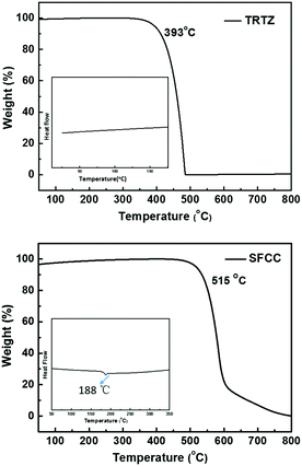
The synthetic route to the target molecule SFCC is depicted in Scheme 1. The precursor 2-(4-fluorophenyl)-4,6-diphenyl-1,3,5-triazine was synthesized through a facile Suzuki–Miyaura coupling reaction and the intermediate 3-bromo-9-(4-(4,6-diphenyl-1,3,5-triazin-2-yl)phenyl)-9H-carbazole was prepared via a simple nucleophilic reaction with mono-brominated carbazole. This reaction intermediate, however, exhibits a very low solubility in common organic solvents such as hexane, CH2Cl2, chloroform and THF. Thus, the crude product was not further purified by column chromatography, but simply isolated by filtration and washing. However, when it was directly used in the next Suzuki–Miyaura coupling reaction with 2-(9,9′-spirobifluoren-3-yl)-4,4,5,5-tetramethyl-1,3,2-dioxaborolane using THF as the solvent, the suspended intermediate gradually disappeared and the final reaction solutions became clear after 24 hours of reflux, giving a good yield of the product SFCC.34 The decomposition temperature (Td, corresponding to 5% weight loss in thermogravimetric analysis) and glass transition temperature (Tg, obtained by differential scanning calorimetry (DSC)) (Fig. 1) of SFCC are 515 and 188 °C, respectively, while the Td of TRTZ is 393 °C (no obvious glass transition). This indicates that the introduction of an SBF moiety could improve the thermal and morphological stabilities.In order to examine the effects of the SBF moiety on the SFCC molecule, the photophysical properties of SFCC were studied and the results are used for comparison with the TRTZ. Absorption spectra were recorded in CH2Cl2 while emission spectra were recorded in toluene. As shown in Fig. 2, both compounds exhibit similar spectral shapes, but differ somewhat in their peak positions. The stronger absorptions around 270 nm are attributed to the π–π* transitions of the different conjugated aromatic units, and the much weaker absorptions around 360 nm are assigned to the intramolecular charge-transfer (ICT) transitions from the carbazole block to the cyaphenine moiety. As compared with the reference material TRTZ, it was found that SFCC exhibited an approximately 10 nm red shift in both the room-temperature steady-state emission (attributed to fluorescence) and the 77 K delayed emission (attributed to phosphorescence); such a small shift in spectra may be caused by its decoupled conjugation through meta-linkage, and this shift may be further reduced by another meta-linkage on a more steric C1 position of SBF reported by Poriel et al.31 Thus, there is apparently a smaller shift in energy for T1 than for S1 (perhaps suggesting a more local T1 excitation and a CT S1 excitation), and as a result, the ΔEST for SFCC is estimated to be slightly smaller than that of the reference emitter TRTZ (0.38 vs. 0.43 eV).
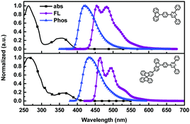 | ||
| Fig. 2 UV/Vis absorption (CH2Cl2, 10−5 mol L−1), steady-state fluorescence (toluene, 10−5 mol L−1, 298 K), and phosphorescence (toluene, 10−4 mol L−1, 77 K) spectra of TRTZ and SFCC. | ||
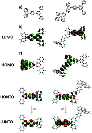
The electronic structures of both materials were simulated by the time-dependent density functional theory (TD-DFT) performed at the B3LYP/6-31G(d) level and combined with the natural transition orbital (NTO), which allows us to gain further insights into their electronic properties and the function of the fluorene moiety. As shown in Fig. 3, both materials have well-separated HOMOs and LUMOs, but unlike the HOMO of TRTZ, the HOMO of SFCC extends over one of the fluorine rings as well as the carbazole, resulting in a shallower HOMO energy level (calculated to be −5.27 vs. −5.42 eV) and a decreased HOMO–LUMO energy gap for SFCC; the distribution of the NTOs for both materials indicates that they are localized in the T1 state mainly located on the cyaphenine part, which agrees with the phosphorescence spectra. The ionization energies estimated from the electrochemical measurements (Fig. 4) show the same trend, although the comparison may be of limited validity because the oxidation of SFCC is reversible and that of TRTZ is not. All the pertinent energy level data are summarized in Table 1.
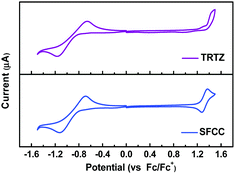 | ||
| Fig. 4 Reductive (THF, 0.1 M Bu4NPF6) and oxidative (CH2Cl2, 0.1 M Bu4NPF6) cyclic voltammograms of TRTZ and SFCC. | ||
| Compounds | λ abs (nm) | λ em (nm) | HOMO/LUMOc (eV) | IP/EAd (eV) | E S/ETe (eV) | ΔESTf (eV) | E S/ETg (eV) | ΔESTh (eV) | f |
|---|---|---|---|---|---|---|---|---|---|
| a UV-vis absorption bands measured in dichloromethane solution at room temperature. b Emission peak in room-temperature steady-state emission spectra measured in toluene solution. c Calculated HOMO and LUMO energy levels (B3LYP/6-31G(d)). d Ionization potential (IP) and electron affinity (EA) estimated from the cyclic voltammograms assuming EIP/EA = −e(Eox/red − Eferrocene + 4.80) (eV), where the potentials are onset values relative to ferrocenium/ferrocene and e is the electronic charge. e Calculated S1 and T1 energies. f Calculated ΔEST. g S1 and T1 estimated from the onset of the room-temperature fluorescence spectra and the highest vibronic band of the phosphorescence spectra. h ΔEST estimated from the experimental S1 and T1 energies. | |||||||||
| TRTZ | 262/354 | 420 | −5.42/−1.95 | 5.60/3.43 | 2.98/2.66 | 0.32 | 3.01/2.58 | 0.43 | 0.3311 |
| SFCC | 268/363 | 434 | −5.27/−1.97 | 5.49/3.46 | 2.86/2.61 | 0.25 | 2.91/2.53 | 0.38 | 0.3305 |
Both the transient PL curves (Fig. 5) of SFCC and TRTZ doped in bis-(2-(diphenylphosphino)phenyl)ether oxide (DEPEO) films (30 wt%) measured at 300 K consist of a fast and a slower component. Notably, the kRISC of SFCC is greater than that of TRTZ (Table 2). In addition, the PLQYs of TRTZ and SFCC were found to be 58% and 73%, respectively. As discussed above, the smaller ΔEST of SFCC is beneficial for the RISC. Also, the extension of conjugation by fluorene in the SFCC's backbone may account for the increased PLQY.
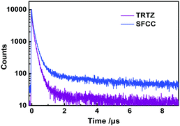 | ||
| Fig. 5 Transient PL decay spectra of TRTZ and SFCC doped into DPEPO films (30 wt%) at room temperature. | ||
| Compounds | τ PF (μs) | τ DF (μs) | Φ PF (%) | Φ DF (%) | Φ (%) | k RISC (104 s−1) | k PF (106 s−1) | k DF (104 s−1) | k ISC (106 s−1) |
|---|---|---|---|---|---|---|---|---|---|
| a τ PF (the prompt lifetime) and τDF (the delayed lifetime) obtained from the transient PL decay of doped films (30% in the DPEPO host was performed using a streak camera at room temperature). b Φ PF (the prompt PLQY) and ΦDF (the delayed PLQY) estimated according to the prompt and delayed proportions in transient decay curves. c Absolute PLQY of the doped films measured using an integrating sphere. | |||||||||
| TRTZ | 0.15 | 13.5 | 39 | 19 | 58 | 5.99 | 6.67 | 7.41 | 4.08 |
| SFCC | 0.19 | 12 | 32 | 41 | 73 | 15.53 | 5.26 | 8.33 | 3.57 |
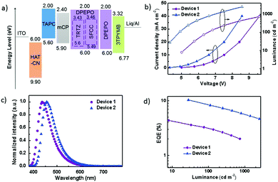
The performance of the OLEDs using SFCC and TRTZ as emitters was compared using the following device architecture: glass substrate: ITO/HAT-CN (10 nm)/TAPC (35 nm)/mCP (10 nm)/DPEPO: 30 wt% dopant (TRTZ or SFCC, 20 nm)/3TPYMB (40 nm)/Liq (2 nm)/Al (120 nm) (TRTZ for device 1, SFCC for device 2). As displayed in Fig. 6a, indium tin oxide (ITO) and aluminium were the anode and the cathode, respectively. 1,1-Bis[4-[N,N-di(p-tolyl)amino]phenyl]cyclohexane (TAPC) was used for the hole-transport layers (HTLs) and N,N′-dicarbazolyl-3,5-benzene (mCP) as the exciton-blocking layer (HBL). DPEPO doped with 30 wt% emitter was used as the emitting layer (EML). Tris-[3-(3-pyridyl)mesityl]borane (3TPYMB) acted as the electron-transporting layer (ETL). 1a,1,4,5,8,9,11-Hexaazatriphenylene-hexacarbonitrile (HAT-CN) and Liq served as the hole-and electron-injection materials, respectively.
Representative electroluminescence (EL) characteristics of the devices are shown in Fig. 6b–d, and the performance parameters are summarized in Table 3. A maximum EQE of 10.59% was obtained in device 2 (Fig. 6b), which is significantly higher than that of device 1 (4.46%). It should be noted that the maximum efficiencies for TRTZ and SFCC were at different brightness levels, for example, at a similar brightness of around 30 cd m−2, the efficiency difference became larger (10.59% for SFCC at 28 cd m−2vs. 3.68% for TRTZ at 33 cd m−2). In addition, device 2 based on SFCC exhibited a slightly lower driving voltage, which may be attributed to a lower IP of SFCC and a reduced barrier for hole injection into the emissive layer.
3. Conclusion
In summary, we utilized a C3-linked 9,9′-spiro-bifluorene substituent in the construction of a blue TADF emitter for the first time to synthesize a new material, SFCC. We found the modification offers two major advantages: firstly, extension of the HOMO distribution onto the fluorene unit helps to decrease ΔEST; and secondly, the PLQY obtained is higher than that for a reference material TRTZ without SBF modification. Both factors are favorable for TADF emitters and together provide a new way of increasing the PLQY without decreasing ΔEST. In addition, the SFCC showed a significantly higher Tg and better thermal properties, owing to its bulky spiro-structure. For the fabrication of TADF-based devices, we successfully obtained an EQE of 10.59% for SFCC, which is superior to an EQE of 4.46% obtained for TRTZ under the same device architecture. More work is needed to establish whether the introduction of C3-fluorene in C3-carbazole represents a general strategy for improving the TADF properties of the D–A emitters.4. Experimental section
4.1 General methods
All chemicals and reagents were used as received from commercial sources without further purification. Mass spectra (EI) were recorded on a Micromass Autospace mass spectrometer and Applied Biosystems 4700 Proteomics Analyzer mass spectrometer. 1H NMR and 13C NMR spectra were recorded on a Bruker 600 spectrometer at room temperature. Elemental analyses (C, H and N) were carried out using a VARIO EL III elemental analyzer. UV-vis absorption spectra were recorded on a Perkin Elmer Lambda 750 spectrophotometer. Fluorescence and phosphorescence spectra were recorded on a Hitachi F-4600 fluorescence spectrophotometer. Differential scanning calorimetry (DSC) was performed on a TA DSC 2010 unit at a heating rate of 10 °C min−1 under nitrogen. The glass transition temperatures (Tg) were determined from the second heating scan. Thermogravimetric analysis (TGA) was performed on a TA SDT 2960 instrument at a heating rate of 10 °C min−1 under nitrogen, the temperature at 5% weight loss was used as the decomposition temperature (Td). Cyclic voltammetry (CV) was carried out using a CHI600 voltammetric analyzer at room temperature with ferrocenium–ferrocene as the internal standard. Deaerated dichloromethane (DCM) was used as the solvent for oxidation and deaerated tetrahydrofuran (THF) was used as the solvent for reduction scan with tetrabutylammonium hexafluorophosphate (0.1 M) as the supporting electrolyte. The cyclic voltammograms were obtained at a scan rate of 0.1 V s−1. Transient PL decays were measured using a single photon counting spectrometer from HORIBA Jobin Yvon. DFT calculations were performed utilizing the B3LYP/6-31G(D) atomic basis set. The PLQYs were measured using a Fluorolog HORIBA 320. The ground state geometry optimization was performed with DFT with the B3LYP hybrid functional and def2svp basis set using Gaussian 09 and the excited state calculations were conducted using TD-DFT/PBE1PBE/def2svp. The Multiwfn-3.3.9-bin-Win software was used for orbital composition analysis.4.2 Synthesis and characterization
![[thin space (1/6-em)]](https://www.rsc.org/images/entities/char_2009.gif) :
:![[thin space (1/6-em)]](https://www.rsc.org/images/entities/char_2009.gif) 3 CH2Cl2/petroleum on silica gel to give a white product weighting 1.76 g (yield 83%). The final material, which weighed 1.1 g, was sublimated before use. 1H NMR (600 MHz, CDCl3) δ 9.06 (d, J = 8.5 Hz, 2H), 8.84 (d, J = 7.0 Hz, 4H), 8.45 (d, J = 1.1 Hz, 1H), 8.25 (d, J = 7.8 Hz, 1H), 8.19 (s, 1H), 7.98 (d, J = 7.6 Hz, 1H), 7.87 (t, J = 7.8 Hz, 4H), 7.78 (d, J = 8.5, 1.4 Hz, 1H), 7.68–7.59 (m, 8H), 7.49 (t, J = 8.6 Hz, 2H), 7.43–7.35 (m, 4H), 7.15 (t, J = 7.2 Hz, 3H), 6.84 (d, J = 12.0, 7.8 Hz, 3H), 6.78 (d, J = 7.6 Hz, 1H). 13C {1H} NMR (600 MHz, CDCl3) δ 171.81, 170.91, 149.21, 148.82, 147.27, 141.78, 141.74, 141.68, 141.55, 140.90, 139.92, 136.13, 135.02, 134.13, 132.66, 130.69, 127.93, 127.28, 125.82, 124.32, 123.90, 120.60, 120.52, 120.07, 120.00, 119.04, 118.88, 110.19, 110.10. MS (m/z): 789.2 [M]+. Anal. calcd for C58H36N4 (%): C 88.30; H 4.60; N 7.10; found: C 88.01, H 4.35, N 7.20.
3 CH2Cl2/petroleum on silica gel to give a white product weighting 1.76 g (yield 83%). The final material, which weighed 1.1 g, was sublimated before use. 1H NMR (600 MHz, CDCl3) δ 9.06 (d, J = 8.5 Hz, 2H), 8.84 (d, J = 7.0 Hz, 4H), 8.45 (d, J = 1.1 Hz, 1H), 8.25 (d, J = 7.8 Hz, 1H), 8.19 (s, 1H), 7.98 (d, J = 7.6 Hz, 1H), 7.87 (t, J = 7.8 Hz, 4H), 7.78 (d, J = 8.5, 1.4 Hz, 1H), 7.68–7.59 (m, 8H), 7.49 (t, J = 8.6 Hz, 2H), 7.43–7.35 (m, 4H), 7.15 (t, J = 7.2 Hz, 3H), 6.84 (d, J = 12.0, 7.8 Hz, 3H), 6.78 (d, J = 7.6 Hz, 1H). 13C {1H} NMR (600 MHz, CDCl3) δ 171.81, 170.91, 149.21, 148.82, 147.27, 141.78, 141.74, 141.68, 141.55, 140.90, 139.92, 136.13, 135.02, 134.13, 132.66, 130.69, 127.93, 127.28, 125.82, 124.32, 123.90, 120.60, 120.52, 120.07, 120.00, 119.04, 118.88, 110.19, 110.10. MS (m/z): 789.2 [M]+. Anal. calcd for C58H36N4 (%): C 88.30; H 4.60; N 7.10; found: C 88.01, H 4.35, N 7.20.
4.3 Device fabrication and measurement
OLED devices were fabricated on ITO glass substrates (110 nm, 15 Ω square−1) under a base pressure of 3 × 10⁻⁶ Torr. The active area of each device was 0.09 cm2. The substrates were cleaned with ethanol, acetone and deionized water, and then dried in an oven before being exposed to UV ozone for 15 minutes. All the organic and electrode materials are thermally evaporated using a Suzhou Fangsheng FS-450 thermal evaporator. The deposition rates and thicknesses of all materials were monitored with oscillating quartz crystals. The deposition rate of the host was controlled at 0.2 nm s−1, and the deposition rate of the dopant was adjusted according to the volume ratio doped in the host materials.The EL and current density–voltage (J–V–L) characteristics of the devices were measured using a constant current source (Keithley 2400 SourceMeter) combined with a photometer (Photo Research SpectraScan PR 655).
Conflicts of interest
There are no conflicts to declare.Acknowledgements
We acknowledge financial supports from the National Key R&D Program of China (No. 2016YFB0400703), the National Natural Science Foundation of China (61475106, 21572152), the Natural Science Foundation of Jiangsu Province (No. BK20151264), the Collaborative Innovation Center of Suzhou Nano Science & Technology (NANO-CIC), 111 project, and the Priority Academic Program Development of Jiangsu Higher Education Institutions (PAPD). The authors thank Hong-Cheng Li for assistance with natural transition orbital (NTO) analysis.Notes and references
- C. W. Tang and S. A. VanSlyke, Appl. Phys. Lett., 1987, 51, 913 CrossRef CAS.
- L. S. Cui, H. Nomura, Y. Geng, J. U. Kim, H. Nakanotani and C. Adachi, Angew. Chem., Int. Ed., 2017, 133, 1593 CrossRef.
- S. F. Wu, S. H. Li, Y. K. Wang, C. C. Huang, Q. Sun, J. J. Liang, L. S. Liao and M. K. Fung, Adv. Funct. Mater., 2017, 27, 1701314 CrossRef.
- H. Uoyama, K. Goushi, K. Shizu, H. Nomura and C. Adachi, Nature, 2012, 492, 234 CrossRef CAS PubMed.
- K. Suzuki, S. Kubo, K. Shizu, T. Fukushima, A. Wakamiya, Y. Murata, C. Adachi and H. Kaji, Angew. Chem., Int. Ed., 2015, 127, 15446 CrossRef.
- D. D. Zhang, L. Duan, D. Q. Zhang, J. Qiao, G. F. Dong, L. D. Wang and Y. Qiu, Org. Electron., 2013, 14, 260 CrossRef CAS.
- Y. Yuan, Y. Hu, Y. X. Zhang, J. D. Lin, Y. K. Wang, Z. Q. Jiang, L. S. Liao and S. T. Lee, Adv. Funct. Mater., 2017, 27, 1700986 CrossRef.
- Y. K. Wang, S. F. Wu, Y. Yuan, S. H. Li, M. K. Fung, L. S. Liao and Z. Q. Jiang, Org. Lett., 2017, 19, 3155 CrossRef CAS PubMed.
- D. D. Zhang, M. H. Cai, Z. Y. Bin, Y. G. Zhang, D. Q. Zhang and L. Duan, Chem. Sci., 2016, 7, 3355 RSC.
- Y. K. Wang, S. H. Li, S. F. Wu, C. C. Huang, S. Kumar, Z. Q. Jiang, M. K. Fung and L. S. Liao, Adv. Funct. Mater., 2018, 1706228 CrossRef.
- Y. Sun, N. C. Giebink, H. Kanno, B. Ma, M. E. Thompson and S. R. Forrest, Nature, 2006, 440, 908 CrossRef CAS PubMed.
- M. Taneda, K. Shizu, H. Tanaka and C. Adachi, Chem. Commun., 2015, 51, 5028 RSC.
- T. Nakagawa, S. Y. Ku, K. T. Wong and C. Adachi, Chem. Commun., 2012, 48, 9580 RSC.
- A. Endo, M. Ogasawara, A. Takahashi, D. Yokoyama, Y. Kato and C. Adachi, Adv. Mater., 2009, 21, 4802 CrossRef CAS PubMed.
- T. A. Lin, T. Chatterjee, W. L. Tsai, W. K. Lee, M. J. Wu, M. Jiao, K. C. Pan, C. L. Yi, K. T. Wong and C. C. Wu, Adv. Mater., 2016, 28, 6976 CrossRef CAS PubMed.
- H. Tanaka, K. Shizu, H. Miyazakia and C. Adachi, Chem. Commun., 2012, 48, 11392 RSC.
- H. Ohkuma, T. Nakagawa, K. Shizu, T. Yasuda and C. Adachi, Chem. Lett., 2014, 43, 1017 CrossRef CAS.
- J. H. Jou, S. Kumar, A. Agrawal, T. H. Li and S. Sahoo, J. Mater. Chem. C, 2015, 3, 2974 RSC.
- Y. We and C. T. Chen, J. Am. Chem. Soc., 2007, 129, 7478 CrossRef PubMed.
- S. L. Tao, Z. K. Peng, X. H. Zhang, P. F. Wang, C. S. Lee and S. T. Lee, Adv. Funct. Mater., 2005, 15, 1716 CrossRef CAS.
- Y. C. Li, Z. H. Wang, X. L. Li, G. Z. Xie, D. C. Chen, Y. F. Wang, C. C. Lo, A. Lien, J. B. Peng, Y. Cao and S. J. Su, Chem. Mater., 2015, 27, 1100 CrossRef CAS.
- Z. Q. Jiang, Z. Y. Liu, C. L. Yang, C. Zhong, J. G. Qin, G. Yu and Y. Q. Liu, Adv. Funct. Mater., 2009, 19, 3987 CrossRef CAS.
- Z. Q. Jiang, H. Q. Yao, Z. Y. Liu, C. L. Yang, C. Zhong, J. G. Qin, G. Yu and Y. Q. Liu, Org. Lett., 2009, 11, 4132 CrossRef CAS PubMed.
- K. T. Wong, Y. Y. Chien, R. T. Chen, C. F. Wang, Y. T. Lin, H. H. Chiang, P. Y. Hsieh, C. C. Wu, C. H. Chou, Y. O. Su, G. H. Lee and S. M. Peng, J. Am. Chem. Soc., 2002, 124, 11576 CrossRef CAS PubMed.
- J. Wang, C. Q. Zhang, C. M. Zhong, S. J. Hu, X. Y. Chang, Y. Q. Mo, X. W. Chen and H. B. Wu, Macromolecules, 2011, 44, 17 CrossRef CAS.
- Y. Liu, L. S. Cui, X. B. Shi, Q. Li, Z. Q. Jiang and L. S. Liao, J. Mater. Chem. C, 2014, 2, 8736 RSC.
- T. P. I. Saragi, T. Spehr, A. Siebert, T. F. Lieker and J. Salbeck, Chem. Rev., 2007, 107, 1011 CrossRef CAS PubMed.
- C. Poriel and J. R. Berthelot, J. Mater. Chem. C, 2017, 5, 3869 RSC.
- L. S. Cui, S. C. Dong, Y. Liu, M. F. Xu, Q. Li, Z. Q. Jiang and L. S. Liao, Org. Electron., 2013, 14, 1924 CrossRef CAS.
- M. M. Xue, C. C. Huang, Y. Yuan, L. S. Cui, Y. X. Li, B. Wang, Z. Q. Jiang, M. K. Fung and L. S. Liao, ACS Appl. Mater. Interfaces, 2016, 8, 20230 CAS.
- L. Sicard, C. Quinton, J. D. Peltier, D. Tondelier, B. Geffroy, U. Biapo, R. Métivier, O. Jeannin, J. R. Berthelot and C. Poriel, Chem. – Eur. J., 2017, 23, 7719 CrossRef CAS PubMed.
- T. Nakagawa, S. Y. Ku, K. T. Wong and C. Adachi, Chem. Commun., 2012, 48, 9580 RSC.
- G. Méhes, H. Nomura, Q. Zhang, T. Nakagawa and C. Adachi, Angew. Chem., Int. Ed., 2012, 51, 11311 CrossRef PubMed.
- X. Y. Liu, F. Liang, L. Ding, S. C. Dong, Q. Li, L. S. Cui, Z. Q. Jiang, H. Chen and L. S. Liao, J. Mater. Chem. C, 2015, 3, 9053 RSC.
- D. D. Zhang, M. H. Cai, Y. G. Zhang, D. Q. Zhang and L. Duan, Mater. Horiz., 2016, 3, 145 RSC.
- B. Wex and B. R. Kaafarani, J. Mater. Chem. C, 2017, 5, 8622 RSC.
- X. K. Chen, Y. Tsuchiya, Y. Ishikawa, C. Zhong, C. Adachi and J. L. Brédas, Adv. Mater., 2017, 29, 1702767 CrossRef PubMed.
| This journal is © the Partner Organisations 2018 |


