Generating a three-dimensional non-fullerene electron acceptor by combining inexpensive spiro[fluorene-9,9′-xanthene] and cyanopyridone functionalities†
Gajanan
Kadam
a,
Anuradha
b,
Anubha
Agarwal
c,
Avinash
Puyad
d,
Duong Duc
La
b,
Richard A.
Evans
e,
Jingliang
Li
 c,
Akhil
Gupta
 *c and
Sheshanath V.
Bhosale
 *f
*f
aDepartment of Organic Chemistry, School of Chemical Sciences, North Maharashtra University, Jalgaon 425001, Maharashtra, India
bSchool of Science, RMIT University, GPO Box 2476, Melbourne, Victoria 3001, Australia
cInstitute for Frontier Materials, Deakin University, Waurn Ponds, Victoria 3216, Australia. E-mail: akhil.gupta@deakin.edu.au; Tel: +61 3 5247 9542
dSchool of Chemical Sciences, Swami Ramanand Teerth Marathwada University, Nanded, 431606, Maharashtra, India
eCSIRO Manufacturing, Bayview Avenue, Clayton South, Victoria, 3169, Australia
fDepartment of Chemistry, Goa University, Taleigao Plateau, Goa, 403206, India. E-mail: svbhosale@unigoa.ac.in; bsheshanath@gmail.com; Tel: +91 (0866) 9609303
First published on 27th March 2018
Abstract
Through the combination of cheaply synthesized structural fragments, spiro[fluorene-9,9′-xanthene] – otherwise termed low-cost spiro – and cyanopyridone, herein we report a new, three-dimensional, small molecule non-fullerene electron acceptor, (5Z,5′Z,5′′E,5′′′E)-5,5′,5′′,5′′′-((((S)-spiro[fluorene-9,9′-xanthene]-2,2′,7,7′-tetrayl)tetrakis(thiophene-5,2-diyl))tetrakis(methaneylylidene))tetrakis(4-methyl-1-octyl-2,6-dioxo-1,2,5,6-tetrahydropyridine-3-carbonitrile) [A1], which was synthesized for use in solution-processable bulk-heterojunction devices and was fully characterized by proton and carbon NMR spectroscopies together with elemental analysis. A1 was synthesized by a facile synthetic methodology using a Knoevenagel condensation reaction and was found to be highly soluble in a variety of common processing solvents such as chloroform and o-dichlorobenzene. Owing to its envisioned design, A1 displayed promising optoelectronic properties, and energy levels complementing those of the conventional donor polymers poly(3-hexylthiophene) [P3HT] and poly({4,8-bis[(2-ethylhexyl)oxy]benzo[1,2-b:4,5-b′]dithiophene-2,6-diyl}{3-fluoro-2-[(2-ethylhexyl)carbonyl]-thieno[3,4-b]thiophenediyl}) [PTB7]. Given its energy levels, solubility and excellent film forming capability, A1 was used in bulk-heterojunction devices as an n-type semiconducting component. The device performances [D![[thin space (1/6-em)]](https://www.rsc.org/images/entities/char_2009.gif) :
:![[thin space (1/6-em)]](https://www.rsc.org/images/entities/char_2009.gif) A 1
A 1![[thin space (1/6-em)]](https://www.rsc.org/images/entities/char_2009.gif) :
:![[thin space (1/6-em)]](https://www.rsc.org/images/entities/char_2009.gif) 1.2 = 5.84% (P3HT); 7.21% (PTB7)] validated the design and use of A1 as an efficient non-fullerene acceptor.
1.2 = 5.84% (P3HT); 7.21% (PTB7)] validated the design and use of A1 as an efficient non-fullerene acceptor.
1. Introduction
The development of renewable energy technologies based on harvesting solar energy at an affordable price is a pressing need for society. The technologies such as organic (otherwise termed bulk-heterojunction) solar cells are highly promising given the advantages, such as lightweight, flexibility and low-cost, they offer.1–4 The development of such devices has seen advancements in the areas of new material design and fabrication strategies. In terms of materials development, donor and acceptor materials have been extensively researched. The conventional donor–acceptor material combinations, such as donor polymer poly(3-hexyl thiophene) (P3HT) and soluble fullerene acceptors, [6,6]-phenyl-C61-butyric acid methyl ester (PC61BM) and its C71 analogue (PC71BM), have been thoroughly studied to understand device design, morphological controls, and consistent device outcome. Despite the achievement of high conversion efficiencies using fullerene acceptors, non-fullerene acceptors have been developed over the past few years as they are seen to possess multiple advantages beyond their fullerene-based counterparts, such as strong light harvesting, easily tunable energy levels, improved morphological stability, and facile synthetic manipulations.5–12Although the fullerene acceptors provide a number of advantages, such as good electron mobility, excellent solubility and the ability to form a favourable nanoscale network with donor semiconducting components, they are afflicted with a number of limitations, e.g. poor chemical and electronic tunability, weak absorption in the visible region, and a large electron affinity that results in low open-circuit voltage.13 Fullerenes are also expensive, thus making their mass uptake challenging. These disadvantages of fullerenes encourage researchers to develop non-fullerene acceptors that can compete with fullerene acceptors by retaining properties, such as strong accepting strength, solubility, and thermal stability, but adding the ability to tune energy levels and scalable synthetic routes. Therefore, the design and development of a potential non-fullerene acceptor based on such requirements is an important and worthy challenge for both organic chemists and device physicists.
It is evident from the recent literature that several structural types, including small molecules and conjugated polymers, have been developed as efficient non-fullerene electron acceptors.14–28 Among the reported literature, the most recent reports on encouraging efficiencies of bulk-heterojunction (BHJ) devices and unique material design are the reports that comprise non-planar, three-dimensional (3D) structural architectures. Such non-planar molecular arrangements can reduce electronic coupling and charge recombination,29 and provide high thermal stability, and favourable solubility. Moreover, such formats can prevent strong intermolecular aggregation, whilst sustaining extended and effective conjugation in each direction for superior photon harvesting. One of the key methods to achieve such properties and a 3D architecture is the utilization of a structural format that can be used centrally and allows multiple functionalities to be placed at its peripheries. The structures like 9,9′-spirobi[fluorene],1,1,2,2-tetraphenylethene and 9,9′-bifluorenylidene are the principal blocks that have been reported in the recent literature to generate 3D architectures. Reviews by H.-W. Luo et al., N. Liang et al. and W. Chen et al. provide such details30–32 and indicate that there is still a large scope for those structural units which can be employed to generate non-planar targets.
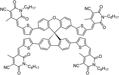
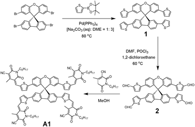
To overcome the high cost and synthetic complexity of the literature reported units, however, in the present study, we have focussed our attention on spiro[fluorene-9,9′-xanthene] (SFX), which is a cheaply synthesized unit and is reported as a “low-cost spiro” by M. Maciejczyk et al.33 This unit has further been reported to produce eco-friendly green organic semiconductors, such as organic light emitting diodes (OLEDs),34 and more recently, perovskite solar cells.30–32,35 Surprisingly, among the reported literature, no derivatives have been described that can be used as non-fullerene acceptors. An additional motivation for our interest in the design of a novel, 3D target molecule based on SFX was the recent success that we were able to achieve using cyanopyridone as a terminal accepting group.36,37 Taking into account the advantages exhibited by cyanopyridone, such as strong accepting strength, low-cost synthesis and capability to be placed at terminals, together with the literature precedence, herein we report the very first combination of SFX and cyanopyridone functionalities to generate a novel, 3D small molecule non-fullerene electron acceptor, (5Z,5′Z,5′′E,5′′′E)-5,5′,5′′,5′′′-((((S)-spiro[fluorene-9,9′-xanthene]-2,2′,7,7′-tetrayl)tetrakis(thiophene-5,2-diyl))tetrakis(methaneylylidene))tetrakis(4-methyl-1-octyl-2,6-dioxo-1,2,5,6-tetrahydropyridine-3-carbonitrile), A1 (Fig. 1). The new target A1 was synthesized via a Knoevenagel condensation reaction between 5,5′,5′′,5′′′-(spiro[fluorene-9,9′-xanthene]-2,2′,7,7′-tetrayl)tetrakis(thiophene-2-carbaldehyde) and cyanopyridone (Scheme 1; Experimental section). The reaction protocol was very simple and was carried out in methanol at reflux for 24 h. The structure of A1 was confirmed by 1H and 13C NMR spectroscopies, MALDI-TOF and elemental analysis (for experimental spectra see the ESI†). The molecule A1 was found to be highly soluble in most of the routinely used laboratory solvents, e.g. chlorobenzene, chloroform and o-dichlorobenzene, a prerequisite for fabricating solution-processable BHJ devices. Our idea of designing A1 as a non-fullerene acceptor was validated as the solution-processable BHJ devices comprising two different commercially available donor polymers, poly(3-hexylthiophene) [P3HT] and poly({4,8-bis[(2-ethylhexyl)oxy]benzo[1,2-b:4,5-b′]dithiophene-2,6-diyl}{3-fluoro-2-[(2-ethylhexyl)carbonyl]-thieno[3,4-b]thiophenediyl}) [PTB7], afforded very encouraging and high device outcomes [(P3HT![[thin space (1/6-em)]](https://www.rsc.org/images/entities/char_2009.gif) :
:![[thin space (1/6-em)]](https://www.rsc.org/images/entities/char_2009.gif) A1 1
A1 1![[thin space (1/6-em)]](https://www.rsc.org/images/entities/char_2009.gif) :
:![[thin space (1/6-em)]](https://www.rsc.org/images/entities/char_2009.gif) 1.2 = 5.84%); (PTB7
1.2 = 5.84%); (PTB7![[thin space (1/6-em)]](https://www.rsc.org/images/entities/char_2009.gif) :
:![[thin space (1/6-em)]](https://www.rsc.org/images/entities/char_2009.gif) A1 1
A1 1![[thin space (1/6-em)]](https://www.rsc.org/images/entities/char_2009.gif) :
:![[thin space (1/6-em)]](https://www.rsc.org/images/entities/char_2009.gif) 1.2 = 7.21%)]. Not only is A1 the first reported example in the literature where a unique combination of cheaply synthesized building blocks, SFX and cyanopyridone, has been carried out, but the device outcome reported herein is among the reasonable and encouraging efficiencies, apart from the class of ITIC-based acceptors,23–25 that has been achieved using a simple device architecture and without any special treatment of either the blend solution or the overall device. This work confirms the idea that 3D structural formats are highly efficient non-fullerene acceptor architectures that hold strong promise for organic photovoltaic (OPV) research. The current work is a continuation of our efforts made in the design and development of small molecule chromophores for OPV applications.38–40
1.2 = 7.21%)]. Not only is A1 the first reported example in the literature where a unique combination of cheaply synthesized building blocks, SFX and cyanopyridone, has been carried out, but the device outcome reported herein is among the reasonable and encouraging efficiencies, apart from the class of ITIC-based acceptors,23–25 that has been achieved using a simple device architecture and without any special treatment of either the blend solution or the overall device. This work confirms the idea that 3D structural formats are highly efficient non-fullerene acceptor architectures that hold strong promise for organic photovoltaic (OPV) research. The current work is a continuation of our efforts made in the design and development of small molecule chromophores for OPV applications.38–40
2. Results and discussion
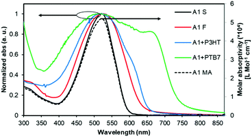
The normalized optical absorption spectra of A1 in chloroform solution, and as a thin solid and blend films are shown in Fig. 2. In solution, A1 exhibited strong absorption with an absorption maximum (λmax) at 518 nm (molar extinction coefficient = ∼52![[thin space (1/6-em)]](https://www.rsc.org/images/entities/char_2009.gif) 000 L Mol−1 cm−1). The thin film spectrum of A1 was red-shifted by 10 nm when compared with its solution spectrum. The blend film spectra of A1 (with P3HT and PTB7) indicated strong light-harvesting ability, and in particular with PTB7 where the pristine film absorption of A1 complemented very well with the absorption profile of PTB7, thus suggesting that the blend film has promising absorption over the whole of the visible region. This further confirms that the use of a narrow band-gap donor polymer like PTB7 is indeed helpful for (1) fine tuning energy levels, (2) exhibiting favourable and well-intermixed blend morphology, and (3) presumably enhancing BHJ performance when compared with a wide band-gap donor polymer P3HT.
000 L Mol−1 cm−1). The thin film spectrum of A1 was red-shifted by 10 nm when compared with its solution spectrum. The blend film spectra of A1 (with P3HT and PTB7) indicated strong light-harvesting ability, and in particular with PTB7 where the pristine film absorption of A1 complemented very well with the absorption profile of PTB7, thus suggesting that the blend film has promising absorption over the whole of the visible region. This further confirms that the use of a narrow band-gap donor polymer like PTB7 is indeed helpful for (1) fine tuning energy levels, (2) exhibiting favourable and well-intermixed blend morphology, and (3) presumably enhancing BHJ performance when compared with a wide band-gap donor polymer P3HT.
In order to obtain information about the theoretical density distribution of A1, the Gaussian 09 ab initio/DFT quantum chemical simulation package was employed to acquire the results represented in the present work.41 The geometry optimization of A1 with truncated alkyl chains was carried out at the B3LYP/6-31G(d) level of theory and the frontier molecular orbitals (FMOs) were generated using Avogadro42,43 (for details of the DFT calculations, see Table S1 and Fig. S1, ESI†). The DFT calculations indicated that the lowest unoccupied molecular orbital (LUMO) and the highest occupied molecular orbital (HOMO) densities were evenly dispersed over the entire molecular backbone, a recent finding that is quite common with high-performing, small-molecule non-fullerene electron acceptors.15,16,44 Furthermore, in order to understand the nature of charge transfer transition, we conducted time-dependent DFT calculations (TD-DFT). The TD-DFT calculations provide excitation energies and oscillator strengths (denoted by f) of the lowest singlet states. The computed absorption spectrum (see Fig. S2, ESI†) shows transition peaks at 539 nm and 512 nm, with the former peak mainly described as the HOMO/LUMO transition (H → L = 95%). Consequently, the subsequent analysis of the transition density matrix via natural transition orbitals (NTOs) produces a pair of NTOs with a very similar character as the corresponding HOMO/LUMO pair (see Fig. S3, ESI†). The experimental estimation of the HOMO was carried out using photoelectron spectroscopy in air (PESA) and the LUMO energy level was calculated using the method reported by P. I. Djurovich et al.45 (for the PESA curve, see Fig. S4, ESI†). The HOMO (−5.81 eV) and the LUMO (−3.78 eV) values are depicted in the energy level diagram (see Fig. S5, ESI†), which indicates that the energy levels of A1 are complementing excellently with the energy levels of two different types of donor polymers, P3HT and PTB7. The energy levels’ alignment indicates that the devices comprising standard donor polymers and A1 indeed guarantee a high open-circuit voltage (Voc), which is certainly advantageous, when compared with the devices incorporating the conventional fullerene acceptor. We further realized that the organic semiconductors, whether donors or acceptors, should also be thermally stable so that they can handle tough fabrication conditions, e.g. annealing at a higher temperature such as 100 °C. Keeping this criterion in mind, we conducted thermogravimetric analysis (TGA). The TGA analysis revealed that A1 is a thermally stable chromophore and the organic solar cell device incorporating A1 can be well annealed, if required. For the TGA spectrum, see Fig. S6, ESI.†
Once it was established that A1 is adequately soluble in a variety of common organic solvents, is thermally and chemically stable, and has energy levels compatible with those of donor polymers, P3HT and PTB7, we fabricated solution-processable BHJ devices using A1 as a non-fullerene acceptor. Though we realised that the pristine and P3HT blend film spectra of A1 are somewhat similar, we still chose to fabricate BHJ devices using P3HT. This was primarily done to realise the potential of A1 with the historic benchmark polymer and to understand its exciton dissociation efficacy. That being said, we expected the outcome of the P3HT-based devices to be inferior when compared with PTB7-based devices given the latter's complementary absorption with A1. Considering the efficacy of A1 as an acceptor and its proposed testing with two different donor polymers, we chose a simple device architecture, indium-tin oxide (ITO)/poly(3,4-ethylenedioxythiophene):polystyrene sulfonate (PEDOT:PSS, 38 nm)/active layer (∼70 nm)/Ca (20 nm)/Al (100 nm), where the active layer was a 1![[thin space (1/6-em)]](https://www.rsc.org/images/entities/char_2009.gif) :
:![[thin space (1/6-em)]](https://www.rsc.org/images/entities/char_2009.gif) 1.2 blend of P3HT/PTB7
1.2 blend of P3HT/PTB7![[thin space (1/6-em)]](https://www.rsc.org/images/entities/char_2009.gif) :
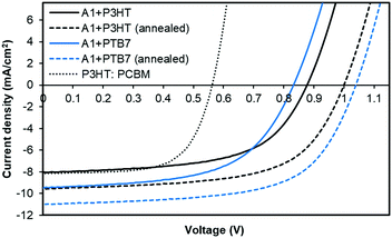
:![[thin space (1/6-em)]](https://www.rsc.org/images/entities/char_2009.gif) A1, respectively, spin-cast from o-dichlorobenzene atop a PEDOT:PSS surface. Taking advantage of the literature findings and our own understanding of the BHJ device architecture, we used a high boiling point solvent and annealed our active surfaces at 110 °C for five minutes. We also fabricated control devices based on P3HT:PC61BM combination. With the PTB7:A1 combination, the device outcome was highly encouraging and the cell parameters, Voc, short-circuit current density (Jsc), fill factor (FF) and power conversion efficiency (PCE), reached 1.04 V, 11.01 mA cm−2, 0.63, 7.21%, respectively. With P3HT combination, the achieved device parameters, Voc, Jsc, FF and PCE, were 1.01 V, 9.56 mA cm−2, 0.61, and 5.84%, respectively. Both of the devices achieved high open-circuit voltages as was predicted from the energy level diagram. This is consistent with the measured LUMO level of A1 and the HOMO levels of the donor polymers. The unannealed devices with a similar donor
A1, respectively, spin-cast from o-dichlorobenzene atop a PEDOT:PSS surface. Taking advantage of the literature findings and our own understanding of the BHJ device architecture, we used a high boiling point solvent and annealed our active surfaces at 110 °C for five minutes. We also fabricated control devices based on P3HT:PC61BM combination. With the PTB7:A1 combination, the device outcome was highly encouraging and the cell parameters, Voc, short-circuit current density (Jsc), fill factor (FF) and power conversion efficiency (PCE), reached 1.04 V, 11.01 mA cm−2, 0.63, 7.21%, respectively. With P3HT combination, the achieved device parameters, Voc, Jsc, FF and PCE, were 1.01 V, 9.56 mA cm−2, 0.61, and 5.84%, respectively. Both of the devices achieved high open-circuit voltages as was predicted from the energy level diagram. This is consistent with the measured LUMO level of A1 and the HOMO levels of the donor polymers. The unannealed devices with a similar donor![[thin space (1/6-em)]](https://www.rsc.org/images/entities/char_2009.gif) :
:![[thin space (1/6-em)]](https://www.rsc.org/images/entities/char_2009.gif) acceptor weight ratio provided a satisfactory outcome too and the PCE values reached 4.50% and 4.13% with PTB7 and P3HT, respectively. In contrast, the maximum PCE reached 3.03% for a controlled device based on P3HT:PC61BM. For current–voltage (J–V) curves and detailed device parameters, see Fig. 3 and Table S2, ESI,† respectively.
acceptor weight ratio provided a satisfactory outcome too and the PCE values reached 4.50% and 4.13% with PTB7 and P3HT, respectively. In contrast, the maximum PCE reached 3.03% for a controlled device based on P3HT:PC61BM. For current–voltage (J–V) curves and detailed device parameters, see Fig. 3 and Table S2, ESI,† respectively.
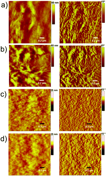
The PTB7-based devices clearly outperform devices based on P3HT under similar conditions. The improvement is mostly due to an increase in the short-circuit current density, a finding that is consistent with the broader blend film absorption of PTB7 and A1. A similar pattern was observed for the incident photon-to-current conversion efficiency (IPCE) measurement where a much broader and stronger response was observed for PTB7-based devices when compared with P3HT-based devices, see Fig. 4 for IPCE spectra. The IPCE maxima of 64% (at 570 nm) and 48% (at 550 nm) were attained for the PTB7- and P3HT-based devices, respectively. Though the broadness of these spectra indicated that both donor and acceptor components in active blends made a considerable contribution to the IPCE and Jsc, the PTB7-based spectrum spanned over most of the visible region, typically ranging from 350 nm to 820 nm, thus suggesting better light-harvesting and a superior blending of donor and acceptor domains. Furthermore, the photocurrents obtained from the IPCE data were in close agreement with those of the current–voltage measurements conducted under the one Sun conditions. The high-quality intermixing of donor and acceptor domains in the case of the PTB7 blend was further confirmed by atomic force microscopy (AFM) analysis, which was conducted in tapping mode, where a much smoother surface with more desirable morphology was observed when compared with the P3HT blend. The actual surface morphologies of the blend films of P3HT![[thin space (1/6-em)]](https://www.rsc.org/images/entities/char_2009.gif) :
:![[thin space (1/6-em)]](https://www.rsc.org/images/entities/char_2009.gif) A1 and PTB7
A1 and PTB7![[thin space (1/6-em)]](https://www.rsc.org/images/entities/char_2009.gif) :
:![[thin space (1/6-em)]](https://www.rsc.org/images/entities/char_2009.gif) A1 (1
A1 (1![[thin space (1/6-em)]](https://www.rsc.org/images/entities/char_2009.gif) :
:![[thin space (1/6-em)]](https://www.rsc.org/images/entities/char_2009.gif) 1.2 w/w) are shown in Fig. 5. The annealed blend surfaces showed surface roughnesses of 1 nm (PTB7:A1) and 6.7 nm (P3HT:A1), thus suggesting that A1 is a type of non-fullerene acceptor which is highly miscible with a variety of donor polymers, for instance narrow and broad band-gap polymers. The AFM analyses further validated the idea of using a high boiling point solvent as it produced much smoother films which were free from discernible lumps and cracks.
1.2 w/w) are shown in Fig. 5. The annealed blend surfaces showed surface roughnesses of 1 nm (PTB7:A1) and 6.7 nm (P3HT:A1), thus suggesting that A1 is a type of non-fullerene acceptor which is highly miscible with a variety of donor polymers, for instance narrow and broad band-gap polymers. The AFM analyses further validated the idea of using a high boiling point solvent as it produced much smoother films which were free from discernible lumps and cracks.
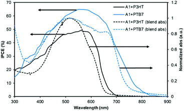 | ||
| Fig. 4 The IPCE curves of the best performing devices described in Fig. 3. The solid lines correspond to IPCE spectra and the dotted lines represent blend film absorption profiles. | ||
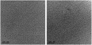
Furthermore, the transmission electron microscopy (TEM) analysis indicated a fine and featureless appearance that was observed for both the blends (Fig. 6), with the quality of PTB7:A1 significantly finer than the P3HT:A1 combination. It is apparent that such uniform and regularized blend surfaces usually result in relatively high values of Jsc and FF, as is the case of A1 blends, and with PTB7 in particular. Furthermore, we conducted X-ray diffraction (XRD) analysis in order to observe whether the blend surfaces are crystalline or amorphous. Both the blend surfaces were found to be amorphous, thus ruling out the possibility of granular morphologies (for XRD spectra, see Fig. S7, ESI†). This indicated that it was the significant miscibility of A1 with two different types of donor polymers that contributed to the observed device performance. This further validates the design concept used in A1, and with the cheaply synthesized building blocks, SFX and cyanopyridone, in particular. The excellent performance of A1 as a non-fullerene acceptor suggests that other acceptor groups at the terminals will be worth examining.
3. Conclusions
In summary, we were able to design, synthesize and characterize a novel non-fullerene electron acceptor, coded as A1, which is a SFX core-based material with terminal cyanopyridone functionalities. A1 possessed a non-planar molecular arrangement, promising optoelectronic properties, adequate solubility, thermal and chemical stability, and energy levels complementing excellently with two different types of donor polymers, P3HT and PTB7. Due to favourable morphology, excellent blend film characteristics and high Jsc, the BHJ devices based on the blended films of PTB7:A1 provided a PCE of 7.21%. Not only is A1 the first example in the literature that comprises SFX and cyanopyridone building blocks, but the device parameters outlined herein are among the leading numerals that have been achieved using a simple device design, a 3D molecular architecture, and the use of commercially available donor polymers. The results further indicate that A1 is a highly promising non-fullerene electron acceptor which offers suitability with a range of donors, whether conjugated polymers or small molecules, and that the SFX-core is worth examining for futuristic engineering of non-fullerene acceptors.4. Experimental section
4.1 Materials and methods
All the reactions were carried out under a nitrogen atmosphere, unless otherwise stated. Solvents used for various reactions were dried using a commercial solvent purification/drying system. Solvents used for extractions and column chromatography, and all other reagents were used as supplied by commercial vendors without further purifications or drying. 2,2′,7,7′-Tetrabromospiro[fluorene-9,9′-xanthene] and 4-methyl-1-octyl-2,6-dioxo-1,2,5,6-tetrahydropyridine-3-carbonitrile were prepared according to the reported literature.33,46 Thin layer chromatography (TLC) was performed using 0.25 mm thick plates pre-coated with Merck Kieselgel 60 F254 silica gel, and visualized using UV light (254 and 365 nm). Petroleum spirits with a boiling point range of 40–60 °C were used wherever indicated. Column chromatography was performed on either 40–60 or 20–40 μm silica gel. 1H NMR spectra were recorded at 300, 400 or 500 MHz, as indicated. The following abbreviations were used to explain multiplicities: s = singlet, d = doublet, t = triplet, q = quartet, m = multiplet, br = broad, dd = doublet of doublets, and dt = doublet of triplets. 13C NMR spectra were recorded at 75 or 101 MHz, as indicated. 1H and 13C chemical shifts were calibrated using residual non-deuterated solvent as an internal reference and are reported in parts per million (δ) relative to tetramethylsilane (δ = 0). PESA measurements were recorded using a Riken Keiki AC-2 PESA spectrometer with a power number of 0.5. Samples for PESA were prepared on ITO cleaned glass substrates and were run using a power setting of 10 nW. TGA experiments were carried out using a Q-500 TGA instrument with nitrogen as a purging gas. The samples were heated to 800 °C at a rate of 10 °C per minute under a nitrogen atmosphere. Details of spectroscopic measurements, and device fabrication and characterization of photovoltaic devices were reported previously.36,38,46 Atomic force microscopy topographic maps were directly performed on the active layers of PTB7:A1 and P3HT:A1 blends using an Asylum Research MFP-3D-SA instrument. The AFM was run in intermittent contact mode (tapping mode) using MicroMasch NSC18 tips (typical resonant frequency ∼100 kHz, typical probe radius ∼10 nm and typical aspect ratio 3![[thin space (1/6-em)]](https://www.rsc.org/images/entities/char_2009.gif) :
:![[thin space (1/6-em)]](https://www.rsc.org/images/entities/char_2009.gif) 1). TEM samples were prepared by solvent evaporation on a holey carbon grid and micrographs were produced using a JOEL 1010 100 kV TEM. A Bruker AXS D8 Discover instrument with a general area detector diffraction system (GADDS) using a Cu Kα source was utilized to obtain XRD patterns.
1). TEM samples were prepared by solvent evaporation on a holey carbon grid and micrographs were produced using a JOEL 1010 100 kV TEM. A Bruker AXS D8 Discover instrument with a general area detector diffraction system (GADDS) using a Cu Kα source was utilized to obtain XRD patterns.
4.2 Synthesis
Conflicts of interest
There are no conflicts to declare.Acknowledgements
S. V. B. acknowledges the University Grant Commission (UGC) – Faculty Research Program (India) for providing financial support and the award of a professorship. A. G. acknowledges Dr Gerry Wilson from CSIRO Manufacturing, Clayton, Victoria, Australia, for providing support through a visiting fellow position. A. G. is thankful to the Alfred Deakin Fellowship Scheme at the Institute for Frontier Materials (IFM), Deakin University, Waurn Ponds, Victoria, Australia. A. G. would like to thank Australia India Institute (AII), New Delhi, India for providing an Incoming Leader Fellowship Award that enabled him to carry out this very interesting piece of research and also for supporting him with the necessary requirements for this project. A. G. will further acknowledge the assistance of Mr Aman Tyagi, Program Officer at AII, New Delhi. Anuradha., and A. A. and A. G. acknowledge various testing and analytical facilities at RMIT University, Deakin University, CSIRO Clayton, and Bio21 Institute, University of Melbourne, Melbourne Victoria, Australia. A. P. acknowledges the use of Gaussian 09 procured under the DST-FIST Scheme (Sanction No. FS/FST/PSI-018/2009). J. Li acknowledges the Australian Research Council (ARC) for support through a Future Fellowship project (FT130100057).Notes and references
- G. Yu, J. Gao, J. C. Hummelen, F. Wudl and A. J. Heeger, Science, 1995, 270, 1789 CAS.
- C. J. Brabec, N. S. Sariciftci and J. C. Hummelen, Adv. Funct. Mater., 2001, 11, 15 CrossRef CAS.
- F. C. Krebs, Sol. Energy Mater. Sol. Cells, 2009, 93, 394 CrossRef CAS.
- (a) A. J. Heeger, Chem. Soc. Rev., 2010, 39, 2354 RSC; (b) L. T. Dou, J. B. You, Z. R. Hong, Z. Xu, G. Li, R. A. Street and Y. Yang, Adv. Mater., 2013, 25, 6642 CrossRef CAS PubMed.
- S. Li, Z. Zhang and M. Shi, et al. , Phys. Chem. Chem. Phys., 2017, 19, 3440 RSC.
- Z. Liu, Y. Wu, Q. Zhang and X. Gao, J. Mater. Chem. A, 2016, 4, 17604 CAS.
- F. Fernàndez-Làzaro, N. Zink-Lorre and A. Sastre-Santos, J. Mater. Chem. A, 2016, 4, 9336 Search PubMed.
- C. B. Nielsen, et al. , Acc. Chem. Res., 2015, 48, 2803 CrossRef CAS PubMed.
- Y. Lin and X. Zhan, Mater. Horiz., 2014, 1, 470 RSC.
- S. M. McAfee, J. M. Topple, I. G. Hill and G. C. Welch, J. Mater. Chem. A, 2015, 3, 16393 CAS.
- C. Zhan and J. Yao, Chem. Mater., 2016, 28, 1948 CrossRef CAS.
- E. Kozma and M. Catellani, Dyes Pigm., 2013, 98, 160 CrossRef CAS.
- R. Y. C. Shin, P. Sonar, P. S. Siew, Z. K. Chen and A. Sellinger, J. Org. Chem., 2009, 74, 3293 CrossRef CAS PubMed.
- A. Rananaware, A. Gupta, J. Li, A. Bilic, L. Jones, S. Bhargava and S. V. Bhosale, Chem. Commun., 2016, 52, 8522 RSC.
- H. Patil, W. X. Zu, A. Gupta, V. Chellappan, A. Bilic, P. Sonar, A. Rananaware, S. V. Bhosale and S. V. Bhosale, Phys. Chem. Chem. Phys., 2014, 16, 23837 RSC.
- A. M. Raynor, A. Gupta, H. Patil, A. Bilic and S. V. Bhosale, RSC Adv., 2014, 4, 57635 RSC.
- H. Patil, A. Gupta, B. Alford, D. Ma, S. H. Privèr, A. Bilic and S. V. Bhosale, Asian J. Org. Chem., 2015, 4, 1096 CrossRef CAS.
- X. F. Wu, W. F. Fu, Z. Xu, M. Shi, F. Liu, H. Z. Chen, J.-H. Wan and T. P. Russell, Adv. Funct. Mater., 2015, 25, 5954 CrossRef CAS.
- N. Qiu, H. Zhang, X. Wan, C. Li, X. Ke, H. Feng, B. Kan, H. Zhang, Q. Zhang, Y. Lu and Y. Chen, Adv. Mater., 2017, 29, 1604964 CrossRef PubMed.
- A. Gupta, A. Rananaware, P. S. Rao, D. D. La, A. Bilic, W. Xiang, J. Li, R. A. Evans, S. V. Bhosale and S. V. Bhosale, Mater. Chem. Front., 2017, 1, 1600 RSC.
- O. K. Kwon, J.-H. Park, D. W. Kim, S. K. Park and S. Y. Park, Adv. Mater., 2015, 27, 1951 CrossRef CAS PubMed.
- S. Dai, F. Zhao, Q. Zhang, T.-K. Lau, T. Li, K. Liu, Q. Ling, C. Wang, X. Lu, W. You and X. Zhan, J. Am. Chem. Soc., 2017, 139, 1336 CrossRef CAS PubMed.
- H. Bin, et al. , Nat. Commun., 2016, 7, 13651 CrossRef CAS PubMed.
- W. Zhao, et al. , Adv. Mater., 2016, 28, 4734 CrossRef CAS PubMed.
- Y. Lin, et al. , Adv. Mater., 2015, 27, 1170 CrossRef CAS PubMed.
- D. Xie, et al. , Dyes Pigm., 2018, 148, 263 CrossRef CAS.
- D. Maa, et al. , Dyes Pigm., 2018, 150, 363 CrossRef.
- G. Zhang, et al. , Chem. Rev., 2018 DOI:10.1021/acs.chemrev.7b00535.
- Y. Song, S. Lv, X. Liu, X. Li, S. Wang, H. Wei, D. Li, Y. Xiao and Q. Meng, Chem. Commun., 2014, 50, 15239 RSC.
- H.-W. Luo, et al. , Chin. Chem. Lett., 2016, 27, 1283 CrossRef CAS.
- N. Liang, et al. , Mater. Chem. Front., 2017, 1, 1291 RSC.
- Bottom of Form W. Chen and Q. Zhang, J. Mater. Chem. C, 2017, 5, 1275 RSC.
- M. Maciejczyk, A. Ivaturi and N. Robertson, J. Mater. Chem. A, 2016, 4, 4855 CAS.
- M. Sun, R. Xu, L. Xie, Y. Wei and W. Huang, Chin. J. Chem., 2015, 33, 815 CrossRef CAS.
- K. Liu, et al. , Mater. Chem. Front., 2017, 1, 100 RSC.
- A. Rananaware, A. Gupta, G. Kadam, D. D. La, A. Bilic, W. Xiang, R. A. Evans and S. V. Bhosale, Mater. Chem. Front., 2017, 1, 2511 RSC.
- D. Srivani, A. Agarwal, S. V. Bhosale, A. L. Puyad, W. Xiang, R. A. Evans, A. Gupta and S. V. Bhosale, Chem. Commun., 2017, 53, 11157 RSC.
- A. Gupta, V. Armel, W. Xiang, G. Fanchini, S. E. Watkins, D. R. MacFarlane, U. Bach and R. A. Evans, Tetrahedron, 2013, 69, 3584 CrossRef CAS.
- R. J. Kumar, Q. I. Churches, J. Subbiah, A. Gupta, A. Ali, R. A. Evans and A. B. Holmes, Chem. Commun., 2013, 49, 6552 RSC.
- A. Gupta, A. Ali, T. B. Singh, A. Bilic, U. Bach and R. A. Evans, Tetrahedron, 2012, 68, 9440 CrossRef CAS.
- M. J. Frisch et al. , Gaussian 09, Revision C.01, Gaussian Inc., Wallingford CT, 2009 Search PubMed.
- Avogadro: an open-source molecular builder and visualization tool, Version 1.1.0. http://avogadro.openmolecules.net/.
- M. D. Hanwell, et al. , J. Cheminf., 2012, 4, 17 CAS.
- S. Li, W. Liu, M. Shi, J. Mai, T.-K. Lau, J. Wan, X. Lu, C.-Z. Li and H. Chen, Energy Environ. Sci., 2016, 9, 604 CAS.
- P. I. Djurovich, et al. , Org. Electron., 2009, 10, 515 CrossRef CAS.
- A. Gupta, et al. , Chem. Commun., 2012, 48, 1889 RSC.
Footnote |
| † Electronic supplementary information (ESI) available: DFT calculations, computed absorption, PESA, TGA, XRD, and experimental spectra. See DOI: 10.1039/c8qm00067k |
| This journal is © the Partner Organisations 2018 |

