Graphene-wrapped nitrogen-doped hollow carbon spheres for high-activity oxygen electroreduction†
Ruguang
Ma
a,
Ruohao
Xing
a,
Gaoxin
Lin
a,
Yao
Zhou
a,
Qian
Liu
*a,
Minghui
Yang
*b,
Chun
Hu
a,
Kang
Yan
c and
Jiacheng
Wang
 *a
*a
aState Key Laboratory of High Performance Ceramics and Superfine Microstructure, Shanghai Institute of Ceramics, Chinese Academy of Sciences, 1295 Dingxi Road, Shanghai 200050, P. R. China. E-mail: qianliu@sunm.shcnc.ac.cn; jiacheng.wang@mail.sic.ac.cn
bNingbo Institute of Materials Technology and Engineering, Chinese Academy of Sciences, Ningbo 315201, P. R. China. E-mail: myang@nimte.ac.cn
cState Key Laboratory of Mechanics and Control of Mechanical Structures, College of Aerospace Engineering, Nanjing University of Aeronautics and Astronautics, 29 Yudao Street, Nanjing 210016, P. R. China
First published on 28th May 2018
Abstract
Graphene wrapping could be used to improve the electrochemical performance of electrodes via the formation of an effective “plane-to-point” conductive network to promote fast electron transfer to the active sites. In this paper, a series of N-doped hollow carbon spheres wrapped by flexible graphene nanosheets (NGCs) have been successfully prepared by the self-assembly of graphene oxide nanosheets onto the surface of hollow polymer spheres, followed by pyrolysis in flowing ammonia. The as-synthesized NGCs show unique hierarchical nanostructures, large hollow cores, large surface areas, and high relative contents of pyridinic and graphitic N groups, as well as uniform wrapping of graphene layers outside of the carbon spheres. The metal-free NGCs show much better activity for the electrocatalytic oxygen reduction reaction with a larger limiting current density and lower onset potential than those without graphene wrapping. They also showed superior long-term stability and fuel crossover effect to commercial Pt/C. These results indicate that graphene wrapping is an effective strategy for improving the activity of electrocatalytic materials via constructing a fast electron transfer network.
Introduction
Polymer electrolyte membrane fuel cells (PEMFCs), directly converting chemical energy into electrical power, have the combined advantages of zero exhaust emission, high energy density and efficiency, quietness and close-to-room-temperature operation.1 However, the cathodic oxygen reduction reaction (ORR) in the PEMFCs has a high reaction overpotential, which has become one of the major limitations for mass production of low-temperature fuel cells.2 At present, carbon-loaded platinum (Pt) composites have been demonstrated as the most efficient and practical electrocatalyst for the ORR, but the scarcity and prohibitive cost of Pt make it difficult to commercialize the fuel cells on a large scale especially for the ORR requiring 40–70% of Pt loading due to its intrinsic sluggish reaction kinetics.1a,3 Moreover, the Pt-based catalysts are also susceptible to carbon monoxide poisoning and methanol crossover effects, thus leading to decreased efficiency of Pt as the ORR electrocatalyst.4 Therefore, great efforts have been made to explore inexpensive and stable ORR electrocatalysts with high activity as the substitutes of Pt-based catalysts.At present, two categories of nonprecious electrocatalysts have been developed. One is earth-abundant transition -based materials (e.g. Fe, Ni, Mn, Co, etc.), which still suffer from low activity and selectivity, and detrimental environmental effects derived from the catalyst waste.5 The other is heteroatom-doped metal-free carbon-based materials (e.g., N, B, S, P, etc.),6 which have been swiftly and intensively studied because of their many advantages of relative low cost, adjustable porosity, excellent chemical and thermal stability and good resistance to methanol crossover effects. Doping of heteroatoms into the carbon frameworks could adjust the electronic structures, surface basicity, surface hydrophilicity and electric conductivity, thus changing the chemisorption energy of O2 and even the reaction mechanism (2e−/4e−) of the catalysts, resulting in enhanced performance for the ORR.7 The doped N atoms are beneficial for the ORR with a direct 4e− pathway,8 while P, B, and S atoms incorporated into the carbon network could promote the formation of peroxide derived from a 2e− process.9 Compared to other non-precious-metal ORR electrocatalysts, N-doped carbon materials have some unique merits of low-cost, environmental friendliness, and high activity. Recently, various kinds of N-doped carbon materials, including N-doped mesoporous carbons,10 N-doped carbon nanofibers,11 N-doped graphene,12 N-doped carbon aerogels,13 N-doped carbon spheres,14etc., have been reported toward the ORR. However, most of these materials demonstrate poor graphitization, decreasing the electron transfer and thus leading to both low electrocatalytic activity and reaction selectivity.
Graphene is a two-dimensional (2D) single-atom-thick sheet of sp2-hybridized carbon atoms.15 It possesses excellent properties including high carrier mobility (∼200![[thin space (1/6-em)]](https://www.rsc.org/images/entities/char_2009.gif) 000 cm2 V−1 s−1), superior thermal conductivity (∼5000 W m−1 K−1), large surface area (2630 m2 g−1), an ambipolar electric field effect, and the room-temperature quantum Hall effect.16 Therefore, flexible graphene nanosheets could act as the conductive pathway for electron transfer when used as the conductive wrapping layer for metal oxides.17 The resulting graphene/metal oxides have improved conductivity through forming an effective “plane-to-point” conductive network, showing increased performance as the electrode materials of lithium batteries. Also, flexible graphene nanosheets are prone to wrap on the surface of oxygen-containing solid surfaces via chemisorption and the force of electrostatic absorption.
000 cm2 V−1 s−1), superior thermal conductivity (∼5000 W m−1 K−1), large surface area (2630 m2 g−1), an ambipolar electric field effect, and the room-temperature quantum Hall effect.16 Therefore, flexible graphene nanosheets could act as the conductive pathway for electron transfer when used as the conductive wrapping layer for metal oxides.17 The resulting graphene/metal oxides have improved conductivity through forming an effective “plane-to-point” conductive network, showing increased performance as the electrode materials of lithium batteries. Also, flexible graphene nanosheets are prone to wrap on the surface of oxygen-containing solid surfaces via chemisorption and the force of electrostatic absorption.
Herein, we develop a facile strategy of synthesizing graphene nanosheet wrapped nitrogen-doped hollow carbon spheres (NGCs) as high-activity electrocatalysts for the ORR. This unique nanocomposite was prepared via graphene wrapping of hollow polymer spheres (HPSs) with large hollow cores, followed by direct pyrolysis in flowing ammonia to dope N atoms within the carbon framework. In the resulting composites of NGCs, hollow carbon spheres with diameters of 100–150 nm and a thickness of ∼20 nm are uniformly encapsulated by flexible graphene sheets. The thermal treatment in ammonia at high temperature not only introduces the doped N atoms as the active sites for the ORR, but also removes most of the oxygen-containing functional groups on the graphene oxide (GO) nanosheets, thus increasing the conductivity of the composites. The NGCs show not only hierarchical nanostructures, but also a large surface area of over 600 m2 g−1, pore volume of 0.68 cm3 g−1 and variable N-doping level of 3.44–7.96 at% depending on the pyrolysis temperature. Graphene wrapping significantly enhances the ORR activity of hollow carbon spheres in terms of lower onset potential, larger limiting current density and higher reaction selectivity of water formed via a direct four-electron pathway. Moreover, the resulting NGCs also show a superior long-term durability and tolerance to MeOH crossover to commercial Pt/C electrocatalysts.
Experimental
Reagents
The Nafion solution (5 wt%) and triblock copolymers P123 (EO20PO70EO20, Mv = 5800) were purchased from Aldrich. Sodium oleate (SO), hexamethylenetetramine (HMT), anhydrous ethanol (EtOH), 2,4-dihydroxybenzoic acid (DA), and potassium hydroxide (KOH) were bought from Sinopharm Chemical Reagent Co., Ltd. The commercial Pt/C catalyst (20 wt%) was bought from Johnson Matthey (United Kingdom). Graphene oxide (GO) was obtained from Nanjing Xianfeng Nanomaterials Company. All solvents and chemicals above were analytical grade and were utilized without further purification.Material synthesis
Structural characterization
Transmission electron microscopy (TEM) images were obtained using a JEOL 2010F electron microscope operating at 200 kV. Samples for analysis were deposited on a carbon micro-grid supported by a copper grid from ultrasonically processed ethanol solutions. Scanning electron microscopy (SEM) images were collected using a JEOL JSM-6700F field emission scanning electron microscope. X-ray photoelectron spectroscopy (XPS) was recorded with an ESCALAB 250 X-ray photoelectron spectrometer with Al Kα (hν = 1486.6 eV) radiation. The carbon monoliths were ground to a powder and then glued onto indium (In) metal particles by pressing for measurements. All spectra were calibrated using 284.5 eV as the line position of adventitious carbon. The source excitation energy was set as 15 keV with an emission current of 20 mA. An analyzer pass energy of 20 eV with a step size of 0.1 eV and dwell time of 100 ms were used. No charging effects were observed when studying the samples by XPS measurements. Nitrogen sorption isotherms were measured using a Micromeritics ASAP 2010 surface area and pore size analyzer at liquid nitrogen temperature (−196 °C). Prior to measurement, the samples were dehydrated under vacuum at 300 °C overnight. The specific surface areas were calculated using the Brunauer–Emmett–Teller (BET) method. The total pore volume was calculated from the amount of nitrogen adsorbed at a relative pressure of 0.99. The pore size distribution curves were calculated from the analysis of the adsorption branch of the isotherm using the Barrett–Joyner–Halenda (BJH) model.Electrode preparation and electrochemical measurements
After grinding, the active sample (5 mg) was dispersed in a mixture of deionized water (0.5 mL), ethanol (0.5 mL), and Nafion solution (5 wt%, 30 μL), followed by sonication until a homogeneous ink was formed.21 Then, the ink (20 μL) was dropped onto the glassy carbon (GC) electrode and then dried to form a catalyst film. A commercial 20 wt% Pt/C (Johnson Matthey) electrode was prepared following the same procedure for comparison. The electrocatalytic ORR activity of the working electrode was studied in a three-electrode system and a 0.1 M KOH solution was used as the electrolyte. Cyclic voltammetry (CV), rotating disk electrode (RDE) and rotating ring-disk electrode (RRDE) techniques were performed in O2-saturated solution using an electrochemical workstation (Pine Instrument Co.). A Pt flake and a saturated calomel electrode (SCE) were used as the counter electrode and reference electrode, respectively. Before the ORR tests, the KOH electrode was saturated by bubbling high-purity O2 for 15 min.For the CV and RDE tests, a GC disk with 5 mm diameter was used for supporting the catalyst. The CV measurements were carried out at a scanning rate of 50 mV s−1 and the working electrode was cycled at least 50 times before collecting the data in O2-saturated KOH solution. The linear sweep voltammetry (LSV) tests were performed at an electrode rotating rate varying from 400 to 2025 rpm (scanning rate of 10 mV s−1) in O2-saturated KOH solution. The current densities were collected from the LSV data and then normalized by the geometric surface area (0.19625 cm2). The electron transfer number (n) is calculated by the Koutechy–Levich (K–L) equation (eqn (a) and (b)) as follows:
 | (a) |
| B = 0.2nFCO2DO22/3ν−1/6 | (b) |
![[thin space (1/6-em)]](https://www.rsc.org/images/entities/char_2009.gif) 485 C mol−1), CO2 is the bulk concentration of O2 (CO2 = 1.2 × 10⁻⁶ mol cm−3), DO2 is the diffusion coefficient of O2 in 0.1 M KOH (DO2 = 1.9 × 10⁻⁵ cm2 s−1), and ν is the kinetic viscosity (ν = 0.01 cm2 s−1).6e The constant 0.2 is adopted when the rotation rate is expressed in rpm.
485 C mol−1), CO2 is the bulk concentration of O2 (CO2 = 1.2 × 10⁻⁶ mol cm−3), DO2 is the diffusion coefficient of O2 in 0.1 M KOH (DO2 = 1.9 × 10⁻⁵ cm2 s−1), and ν is the kinetic viscosity (ν = 0.01 cm2 s−1).6e The constant 0.2 is adopted when the rotation rate is expressed in rpm.
For the RRDE tests, a GC disk electrode (0.2475 cm2 for the geometric surface area) surrounded by a Pt ring (0.1866 cm2 for the geometric surface area) was used as the working electrode. The ring current (Ir) and disk current (Id) were collected from the Pt ring and GC electrode, respectively. The ring potential was held at 0.2 V (vs. SCE) at a scanning rate of 10 mV s−1 and rotating speed of 1600 rpm. The peroxide (HO2−) yields (%) and the transferred electron number (n) can be calculated via the following eqn (c) and (d):22
 | (c) |
 | (d) |
Results and discussion
Hollow polymer spheres (HPSs) were synthesized according to the previous literature.19 As shown in Fig. S1 (ESI†), the as-prepared HPSs are composed of well-monodispersed uniform spheres with hollow structures. The existence of uniform mesopores within the walls of the HPSs has also been proved in the previous research.19 With the evaporation of water from the aqueous mixture of HPSs and graphene oxide (GO) sheets, the hydrophilic GO sheets could gradually stick onto the surface of the carbon spheres due to the chemisorption on oxygen functional groups and the force of electrostatic adsorption and then encapsulate the spheres to form a HPS@GO composite (Fig. 1). The resulting composite was further calcined in NH3 to carbonize the HPSs, dope the N atoms within the carbon framework and reduce the outer GO sheets via thermal removal of oxygen-containing functional groups at high temperature.23 This high-temperature treatment not only affords the doping of the N-related species as the active centres,22b,24 but also increases the carbonization and graphitization degree of the final graphene-wrapped N-doped hollow carbon spheres (NGCs). The outer graphene wrapping could act as a highway for electron transport to N-related catalytic sites within hollow carbon spheres, thus greatly improving the electrocatalytic reactivity for the oxygen reduction reaction (ORR).25 This novel nanocomposite with a unique hierarchical nanostructure has been shown to possess enhanced performance for the ORR with a four-electron-dominant reaction process as discussed in the latter part of the paper.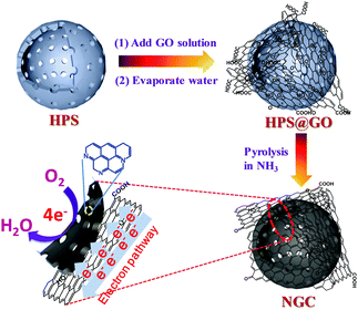 | ||
| Fig. 1 Schematic drawing of preparing graphene-wrapped N-doped hollow carbon spheres (NGCs) as highly active oxygen reduction electrocatalysts with a 4e− reaction process. | ||
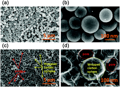
As shown in Fig. 2a and b, the resulting NHCSs without graphene wrapping prepared by direct carbonization of HPSs still possess a good spherical morphology with a smooth surface, even though the HPSs suffered from a two-step heat-treatment at 650 °C in NH3 and then at 1100 °C in Ar. This implies the good morphology maintenance of the robust hollow carbon spheres even after a high-temperature treatment. The diameters of the NHCSs are in the range of 100–150 nm as observed in the SEM images. After the encapsulation of HPSs by GO sheets, followed by pyrolysis, the resulting NGC-1100 shows a quite different morphology from NHCSs without graphene wrapping. As shown in Fig. 2c, many protruding particles indicated by yellow arrows are clearly observed due to the packing of the carbon spheres by graphene nanosheets. Also some macropores shown by red arrows are also formed and they are ascribed to the cavities that resulted from the removal of some carbon spheres. And these pores are more clearly seen in high-resolution SEM images (dashed red circles, Fig. 2d). Moreover, one can see that a spherical particle (dashed yellow ring) has a rough surface, indicating that this carbon sphere is completely wrapped by wrinkled graphene sheets (Fig. 2d). This comparison implies that the present wrapping strategy with graphene nanosheets is highly efficient.
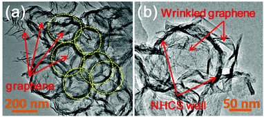
The structure of the graphene-wrapped hollow carbon spheres could be further confirmed by TEM measurements. As presented in Fig. 3a, some rings, highlighted by yellow dashed circles, are clearly observed, indicating the unique hollow structures of the carbons spheres, well matching with the previous results. Moreover, the wrinkled graphene sheets can also be observed and well dispersed with these hollow-structured carbon spheres. As shown in Fig. 3b, graphene sheets well adhere onto the surface of a single hollow carbon sphere, which is well consistent with the observation via SEM. The uniform wrapping by graphene nanosheets could form the sheet-like conductive pathway on the surface of the carbon spheres, thus promoting fast electron transport to the active sites to efficiently improve the electrocatalytic activity and reaction kinetics.17a,26
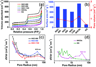
The N2 adsorption–desorption isotherms, and pore size distribution curves of various samples are shown in Fig. 4a, c and d. And the textural properties are also shown in Table S1 (ESI†) and Fig. 4b. All curves showed a typical IV isotherm, indicating the dominant mesoporous characteristics of these samples.18a,27 It is evident that NG has the smallest capacity for N2 adsorption, while the NHCSs show the largest N2 adsorption capacity. NG only has a low surface area of 119 m2 g−1, much smaller than 939 m2 g−1 for the NHCSs (Fig. 4b). The low surface area of NG could be ascribed to the re-stacking of graphene nanosheets after thermal treatment in ammonia.28 Compositing graphene with NHCSs resulted in a little decrease in the surface area of the as-formed NGCs, but the resulting NGC-800 still has a large surface area of 819 m2 g−1. An increase in the pyrolysis temperature could gradually decrease the surface area to 722 m2 g−1 for NGC-950 and 618 m2 g−1 for NGC-1100, possibly due to the collapse of some micropores and narrow mesopores under high-temperature treatment.29 The pore volume values for NGCs show the same changing trend as the specific surface area for all samples. The pore size distribution curves were calculated from the adsorption branches of the isotherms. As shown in Fig. 4c and d, NHCSs and NGCs show the existence of mesopores smaller than 10 nm. The wide mesopores at 40.9 and 42.9 nm are also found due to the aggregating pores of carbon spheres and graphene sheets.30 So the packing of carbon spheres with graphene sheets led to the formation of unique hierarchical structures with high surface area and large pore volume as well as hierarchical pores, which is advantageous for fast mass transport of electrolyte and reactants to the active sites.31
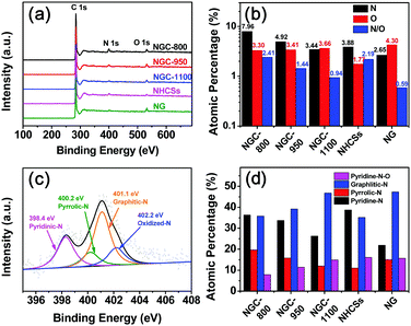
The detailed elemental composition for the different samples was analyzed via X-ray photoelectron spectroscopy (XPS). As shown in Fig. 5a, three peaks at ∼531, 400, and 284 eV are found ascribed to the O 1s, N 1s, and C 1s peaks,32 respectively, implying the successful N-doping into the carbon framework. The N contents of NG and NHCSs are 2.65 and 3.88 at%, respectively (Fig. 5b and Table S2, ESI†). Increasing the treatment temperature from 800 to 1100 °C evidently led to a decrease in the nitrogen content from 7.96 at% for NGC-800 to 3.44 at% for NGC-1100. The higher temperature could cause the loss of doped heteroatoms from the carbon matrix.33 All NGCs showed similar oxygen contents (3.30–3.66 at%) regardless of treatment temperature. The N/O ratio decreased from 2.41 for NGC-800 to 0.94 for NGC-1100. It is notable that the N/O ratio for NGC-1100 is smaller than 2.19 for NHCSs prepared at the same temperature, implying the prompting effect of the wrapped graphene conductive layer on the removal of doped oxygen atoms. The doped N atoms within the NGCs could modify the electronic structures and chemical activities due to the different electronegativity of the nitrogen and carbon atoms, advantageous for the activity improvement.8
The detailed chemical environments for the N-functional groups are analyzed by high-resolution N 1s XPS measurements. As shown in Fig. 5c and Fig. S2 (ESI†), the N 1s spectra can be divided into four peaks, corresponding to pyridinic N (∼398.4 eV), pyrrolic N (∼400.2 eV), graphitic N (∼401.1 eV) and oxidized N (∼402.2 eV).10b,22a,23a,34 The relative atomic percentages of these four groups are presented in Fig. 5d and Table S3 (ESI†). The thermal treatment has a great effect on the N species. By increasing the treatment temperature, the relative contents of both the pyridinic and pyrrolic N groups evidently decrease, while the graphitic N groups show an escalating trend. This complies with the previous reports that high-temperature treatment could transform pyridinic and pyrrolic N groups into graphitic N species.35 Both pyridinic and graphitic N groups play a very important role in improving the electrocatalytic activity toward the ORR.8,22b The former could lower the reaction barriers, while the latter could promote the fast electron transport and thus increase the limiting current density.
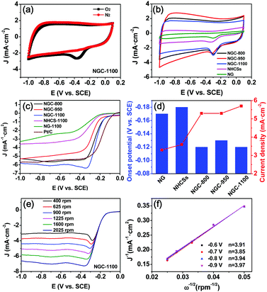
The rotating disk electrode (RDE) and rotating ring disk electrode (RRDE) voltammograms were acquired in a conventional three-electrode system to investigate the electrocatalytic ORR activity of the NGCs and control samples.6d,35 As displayed in Fig. 6a, there is an evident oxygen reduction peak in the CV curve of the GC working electrode coated with NGC-1100 in O2-saturated 0.1 M KOH electrolyte. In sharp contrast, it completely disappeared when O2 was replaced by N2 to saturate the KOH solution. These results imply that O2 could be efficiently reduced on the surface of the working electrode. The CV curves of all samples collected at a sweep rate of 50 mV s−1 in O2-saturated KOH solution are demonstrated in Fig. 6b. It is clearly observed that the NGCs show larger geometric current densities than the N-doped graphene (NG) and NHCSs, implying a higher catalytic activity of NGCs as compared to NG and NHCSs. Moreover, in contrast to those of NG and NHCSs, the CV curves of NGCs exhibit nearly rectangular shapes, showing their high conductivity with a superior capacitive current. It also means a good synergy effect of graphene and the hollow carbon spheres in NGCs on improving the conductivity and further promoting fast electron transfer to the active sites. Among these NGCs prepared at different temperatures, NGC-1100 shows the largest ORR current density at ∼0.29 V (vs. SCE), implying the best ORR activity of NGC-1100.35,36
The ORR activities for all samples were further studied by the linear sweep voltammetry measurements at 1600 rpm and 10 mV s−1 in O2-saturated 0.1 M KOH solution. As shown in Fig. 6c, the NG and NHCSs have moderate ORR activity with a similar onset potential of −0.17 to −0.18 V (vs. SCE) and the limiting current density of 3.3–3.6 mA cm−2 (Fig. 6d). NG showed the lowest ORR activity possibly because its poor surface area restrained mass transfer to the active centers. It is unexpected that wrapping NHCSs by graphene sheets significantly improved the ORR activity in terms of onset potential, half-wave potential and current density. Among the three NGCs, NGC-1100 showed the best ORR activity reflected from its most positive onset potential (−0.12 V) and half-wave potential (−0.23 V), and largest limiting current density (5.7 mA cm−2) at −1.0 V (vs. SCE), although it is still inferior to those of commercial Pt/C (Fig. 6c). These results imply that graphene wrapping evidently improves the ORR activity of the NGCs. The outer wrapped graphene sheet layers could form conductive networks, accordingly lowering the barrier of electron transport to active sites. Moreover, the excellent ORR activity of NGC-1100 also results from the unique hierarchical structures with hollow cores, favorably promoting the fast diffusion of reactants, ions and electrons for the ORR. Notably, the lowest N-doping level of NGC-1100 among the NGCs obtained the best ORR activity among the NGCs, showing that the total N content is not directly determinative of high ORR activity.37 This result also matches well with the previous studies. And the type of N-functional species is also pivotal to the electrocatalytic ORR activity. To study the detailed ORR process on the working electrode, the Koutechy–Levich (K–L) equation was used to calculate the electron transfer number (n) during the ORR process. With increasing rotation speed from 400 to 2025 rpm, the current densities increase which is ascribed to the improved mass transport on the electrode surface (Fig. 6e and Fig. S3, ESI†). The linearity of the K–L plots and near parallelism of the fitting lines imply first-order reaction kinetics toward the concentration of dissolved O2 and approximate n values for the ORR in the potential range of −0.6 to −0.9 V (vs. SCE) (Fig. 6f). The n values for NGC-1100 ranging from 3.85 to 3.97 are very close to those for commercial Pt/C as the ORR electrocatalysts in alkaline solution, demonstrating a high ORR activity with a stable 4e− transfer process for NGC-1100.
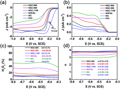
To further investigate the effects of graphene wrapping on the reaction mechanism and catalytic activity, the LSV curves of various samples including commercial Pt/C were collected via a RRDE technique in O2-saturated 0.1 M KOH solution at 1600 rpm (ring potential: 0.2 V vs. SCE). And the polarization curves for the disk and ring electrodes are shown in Fig. 7a and b, respectively. The changing trends for the disk current from the RRDE results are similar to those from the RDE measurements. And NGC-1100 shows the best ORR activity with the most positive half-wave potential. The gap of the high-wave potential for Pt/C and NGC-1100 is only 72 mV, evidently superior to some of the previously-reported carbon-based ORR electrocatalysts including N, B-doped graphene,37 nitrogen-doped hollow carbon hemispheres,36 nitrogen-doped reduced-graphene oxide,38etc. More comparison results are demonstrated in Table S4 (ESI†), showing the superior ORR activity of NGC-1000. The larger current density for the ring electrode suggests the formation of more amount of peroxide (HO2−). It is evident that NGCs show much lower ring electrode current density than NG and NHCSs (Fig. 7b), implying that the binding of graphene and carbon spheres could suppress the HO2− formation. Indeed, the HO2− yields at −0.6 V (SCE) for NGC-800, NGC-950 and NGC-1100 are 11.4%, 16.7% and 9.5%, respectively, much smaller than 49.9% for NG and 34.0% for NHCSs without graphene wrapping. The outer graphene sheets could act as a highway for electron transfer to active sites, and thus are beneficial to impeding the formation of HO2−. The measured yields of NGC-1100 are 6.9–12.1% in a wide potential range of −0.3 to −0.8 V (vs. SCE), very close to 4.8–8.9% for commercial Pt/C, suggesting that both NGC-1100 and Pt/C could catalyze an ORR process with less amount of HO2− as a side product. Accordingly, the calculated n values (3.76–3.86) for NGC-1100 are evidently larger than 3.30–3.52 for NHCSs and 2.96–3.26 for NG (Fig. 7d). And the n values for NGC-1100 are very similar to 3.81–3.90 for Pt/C, demonstrating a desirable four-electron transfer process for the ORR to obtain the maximum energy capacity. The four electron pathway is the most efficient pathway because oxygen could be directly reduced to OH− without the intermediate product (HO2−).2b,39
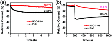
The long-term durability is one of the key challenges for the ORR electrocatalysts in fuel-cell technology.39a The stability of NGC-1100 as well as commercial Pt/C was investigated via chronoamperometric responses at −0.6 V (vs. SCE) and 1600 rpm in O2-saturated 0.1 M KOH solution for 5.5 h. As shown in Fig. 8a, 94.7% of the original current density was maintained for the NGC-1100 electrode, whereas the Pt/C electrode only retained 74.2% of the original one under the same testing conditions. This sharp comparison demonstrated the superior stability of NGC-1100 as the ORR electrocatalyst. NGC-1100 and Pt/C were further studied by measuring the methanol crossover via the chronoamperometric measurements in O2-saturated 0.1 M KOH solution at 1600 rpm (Fig. 8d). When methanol was injected into the electrolyte at 200 s, there is a dramatic loss of the cathodic current for Pt/C and only 60.4% of the initial current density was retained at 1000 s. This implies a poor resistance to methanol crossover for commercial Pt/C. In sharp contrast, after injecting methanol into the cell, the NGC-1100 electrode could retain 83.6% of the cathodic current at 1000 s. Thus, NGC-1100 demonstrates an outstanding tolerance to the crossover effects compared to commercial Pt/C. These results show that metal-free NGC-1100 is a good electrocatalyst for the ORR with high stability.
Conclusions
In conclusion, graphene-wrapped N-doped hollow carbon spheres (NGCs) have been successfully prepared by the self-assembly of graphene oxide nanosheets on the surface of hollow polymer spheres (HPSs), followed by pyrolysis in flowing ammonia. The electron microscopy measurements confirmed the uniform wrapping of graphene sheets on N-doped hollow carbon spheres (NHCSs). Moreover, the carbon spheres could also impede the aggregation of the graphene sheets during the self-assembly and following high-temperature pyrolysis. The resulting nanocomposites show much better electrocatalytic performance for the ORR than NHCSs without graphene wrapping. The optimized NGC-1100 shows a larger limiting current density of 5.7 mA cm−2 than N-doped graphene (NG) (3.3 mA cm−2) and pure NGCSs (3.6 mA cm−2), implying its superior ORR activity derived from the synergy of the graphene and carbon spheres. Moreover, the RRDE measurements indicate that the n values (3.85–3.97) of NGC-1100 are very close to 3.81–3.90 for commercial Pt/C, and are much higher than 2.96–3.26 for NG and 3.30–3.52 for NHCSs. In addition to the advantages of a unique hierarchical structure, large surface area, large hollow core, and high relative content of pyridinic and graphitic N doping in the NGCs, the wrapping graphene layer can play an important role as a conductive network to promote a fast electron transfer and thus improve the ORR activity and selectivity. Moreover, NGC-1100 demonstrates a very high stability during the chronoamperometric experiment compared to commercial Pt/C. The present strategy could be further extended to prepare other heteroatom-doped graphene-wrapped carbon materials for the ORR. Such a unique graphene-wrapped nanocomposite also has potential applications in supercapacitors, batteries, gas storage, etc.Conflicts of interest
There are no conflicts to declare.Acknowledgements
The authors are grateful for the financial support from the National Key Research and Development Program of China (2016YFB0700204), NSFC (51602332 and 51502327), Science and Technology Commission of Shanghai Municipality (15520720400, 15YF1413800 and 16DZ2260603), and One Hundred Talent Plan of Chinese Academy of Sciences. M. Yang would like to thank the National Thousand Youth Talents program of China and Ningbo 3315 program.Notes and references
- (a) S. Mukerjee, S. Srinivasan, M. P. Soriaga and J. Mcbreen, J. Electrochem. Soc., 1995, 142, 1409 CrossRef; (b) A. Bauen and D. Hart, J. Power Sources, 2000, 86, 482 CrossRef.
- (a) M. Lefèvre, J. P. Dodelet and P. Bertrand, J. Phys. Chem. B, 2002, 106, 8705 CrossRef; (b) D. Chu and R. Jiang, Solid State Ionics, 2002, 148, 591 CrossRef.
- V. R. Stamenkovic, B. S. Mun, M. Arenz, K. J. J. Mayrhofer, C. A. Lucas, G. F. Wang, P. N. Ross and N. M. Markovic, Nat. Mater., 2007, 6, 241 CrossRef PubMed.
- (a) B. Seger and P. V. Kamat, J. Phys. Chem. C, 2009, 113, 7990 CrossRef; (b) S. I. Choi, R. Choi, S. W. Han and J. T. Park, Chem. Commun., 2010, 46, 4950 RSC; (c) Y. Li, W. Gao, L. Ci, C. Wang and P. M. Ajayan, Carbon, 2010, 48, 1124 CrossRef.
- (a) J. Huang, N. Zhu, T. Yang, T. Zhang, P. Wu and Z. Dang, Biosens. Bioelectron., 2015, 72, 332 CrossRef PubMed; (b) T. Sun, B. B. Tian, J. Lu and C. Su, J. Mater. Chem. A, 2017, 5, 18933 RSC; (c) X. Zhong, L. Liu, Y. Jiang, X. D. Wang, L. Wang, G. L. Zhuang, X. N. Li, D. H. Mei, J. G. Wang and D. S. Su, ChemCatChem, 2015, 7, 1826 CrossRef; (d) S. Wu, Y. Zhu, Y. Huo, Y. Luo, L. Zhang, Y. Wan, B. Nan, L. Cao, Z. Wang, M. Li, M. Yang, H. Cheng and Z. Lu, Sci. China Mater., 2017, 60, 654 CrossRef; (e) Q. Zhao, Z. Yan, C. Chen and J. Chen, Chem. Rev., 2017, 117, 10121 CrossRef PubMed; (f) Y. Zhou and J. Wang, Nano Adv., 2017, 2, 45 CrossRef.
- (a) G. Liu, X. Li, P. Ganesan and B. N. Popov, Appl. Catal., B, 2009, 93, 156 CrossRef; (b) L. Qu, Y. Liu, J. B. Baek and L. Dai, ACS Nano, 2010, 4, 1321 CrossRef PubMed; (c) Y. Gong, H. Fei, X. Zou, W. Zhou, S. Yang, G. Ye, Z. Liu, Z. Peng, J. Lou, R. Vajtai, B. I. Yakobson, J. M. Tour and P. M. Ajayan, Chem. Mater., 2015, 27, 1181 CrossRef; (d) C. Zhang, N. Mahmood, H. Yin, F. Liu and Y. Hou, Adv. Mater., 2013, 25, 4932 CrossRef PubMed; (e) R. Ma, B. Y. Xia, Y. Zhou, P. Li, Y. Chen, Q. Liu and J. Wang, Carbon, 2016, 102, 58 CrossRef; (f) R. Xing, T. Zhou, Y. Zhou, R. Ma, Q. Liu, J. Luo and J. Wang, Nano-Micro Lett., 2018, 10, 3 CrossRef.
- H. B. Yang, J. Miao, S. F. Hung, J. Chen, H. B. Tao, X. Wang, L. Zhang, R. Chen, J. Gao and H. M. Chen, Sci. Adv., 2016, 2, e1501122 Search PubMed.
- D. H. Guo, R. Shibuya, C. Akiba, S. Saji, T. Kondo and J. Nakamura, Science, 2016, 351, 361 CrossRef PubMed.
- M. Shao, Q. Chang, J.-P. Dodelet and R. Chenitz, Chem. Rev., 2016, 116, 3594 CrossRef PubMed.
- (a) X. Q. Wang, J. S. Lee, Q. Zhu, J. Liu, Y. Wang and S. Dai, Chem. Mater., 2010, 22, 2178 CrossRef; (b) W. Niu, L. Li, X. Liu, N. Wang, J. Liu, W. Zhou, Z. Tang and S. Chen, J. Am. Chem. Soc., 2015, 137, 5555 CrossRef PubMed; (c) G. Lin, R. Ma, Y. Zhou, C. Hu, M. Yang, Q. Liu, S. Kaskel and J. C. Wang, J. Colloid Interface Sci., 2018 DOI:10.1016/j.jcis.2018.05.020.
- (a) M. Sun, X. Wu, X. Deng, W. Zhang, Z. Xie, Q. Huang and B. Huang, Mater. Lett., 2018, 220, 313 CrossRef; (b) Y. Chen, Q. Liu and J. Wang, Nano Adv., 2016, 1, 79 CrossRef.
- (a) R. Imran Jafri, N. Rajalakshmi and S. Ramaprabhu, J. Mater. Chem., 2010, 20, 7114 RSC; (b) Y. Zhang, J. Ge, L. Wang, D. Wang, F. Ding, X. Tao and W. Chen, Sci. Rep., 2013, 3, 2771 CrossRef PubMed.
- Y. Zhou, R. Ma, S. L. Candelaria, J. Wang, Q. Liu, E. Uchaker, P. Li, Y. Chen and G. Cao, J. Power Sources, 2016, 314, 39 CrossRef.
- (a) K. Ai, Y. Liu, C. Ruan, L. Lu and G. M. Lu, Adv. Mater., 2013, 25, 998 CrossRef PubMed; (b) D. Gu, R. Ma, Y. Zhou, F. Wang, K. Yan, Q. Liu and J. Wang, ACS Sustainable Chem. Eng., 2017, 5, 11105 CrossRef.
- A. Bianco, H.-M. Cheng, T. Enoki, Y. Gogotsi, R. H. Hurt, N. Koratkar, T. Kyotani, M. Monthioux, C. R. Park, J. M. D. Tascon and J. Zhang, Carbon, 2013, 65, 1 CrossRef.
- Y. Zhu, S. Murali, W. Cai, X. Li, J. W. Suk, J. R. Potts and R. S. Ruoff, Adv. Mater., 2010, 22, 3906 CrossRef PubMed.
- (a) G. Yu, L. Hu, N. Liu, H. Wang, M. Vosgueritchian, Y. Yang, Y. Cui and Z. Bao, Nano Lett., 2011, 11, 4438 CrossRef PubMed; (b) W. Wei, W. Lv, M.-B. Wu, F.-Y. Su, Y.-B. He, B. Li, F. Kang and Q.-H. Yang, Carbon, 2013, 57, 530 CrossRef; (c) X. Li, X. Zhang, R. Wang, Z. Su, J. Sha and P. Liu, J. Power Sources, 2016, 336, 298 CrossRef.
- (a) J. Wang and Q. Liu, Chem. Commun., 2006, 900 RSC; (b) J. C. Wang and Q. Liu, Nanotechnology, 2006, 17, 2828 CrossRef.
- G. H. Wang, J. Hilgert, F. H. Richter, F. Wang, H. J. Bongard, B. Spliethoff, C. Weidenthaler and F. Schüth, Nat. Mater., 2014, 13, 293 CrossRef PubMed.
- J. C. Wang and Q. Liu, Microporous Mesoporous Mater., 2008, 107, 233 CrossRef.
- (a) R. Ma, Y. Zhou, P. Li, Y. Chen, J. Wang and Q. Liu, Electrochim. Acta, 2016, 216, 347 CrossRef; (b) J. Wang, R. Ma, Y. Zhou and Q. Liu, J. Mater. Chem. A, 2015, 3, 12836 RSC.
- (a) D. Gu, Y. Zhou, R. Ma, F. Wang, Q. Liu and J. Wang, Nano-Micro Lett., 2018, 10, 29 CrossRef; (b) X. Wang, X. Li, L. Zhang, Y. Yoon, P. K. Weber, H. Wang, J. Guo and H. Dai, Science, 2009, 324, 768 CrossRef PubMed.
- (a) J. Wang and Q. Liu, J. Phys. Chem. C, 2007, 111, 7266 CrossRef; (b) H. L. Poh, P. Šimek, Z. Sofer and M. Pumera, ACS Nano, 2013, 7, 5262 CrossRef PubMed.
- T. Horikawa, N. Sakao, T. Sekida, J. i. Hayashi, D. D. Do and M. Katoh, Carbon, 2012, 50, 1833 CrossRef.
- (a) Y. Zhou, Z. Zhou, R. Shen, R. Ma, Q. Liu, G. Cao and J. Wang, Energy Storage Mater., 2018, 13, 189 CrossRef; (b) K. Singh, F. Razmjooei and J. S. Yu, J. Mater. Chem. A, 2017, 5, 20095 RSC.
- X. Li, Y. Zhu, W. Cai, M. Borysiak, B. Han, D. Chen, R. D. Piner, L. Colombo and R. S. Ruoff, Nano Lett., 2009, 9, 4359 CrossRef PubMed.
- (a) Z. Zhang, J. Sun, M. Dou, J. Ji and F. Wang, ACS Appl. Mater. Interfaces, 2017, 9, 16236 CrossRef PubMed; (b) J. Wang and Q. Liu, J. Mater. Res., 2005, 20, 2296 CrossRef; (c) E. Pervaiz, A. K. Tareen and M. Yang, Nano Adv., 2017, 2, 1 CrossRef.
- (a) T.-T. Chen, W.-L. Song and L.-Z. Fan, Electrochim. Acta, 2015, 165, 92 CrossRef; (b) W. Chen, L. Yan and P. R. Bangal, Carbon, 2010, 48, 1146 CrossRef.
- (a) G. Lin, R. Ma, Y. Zhou, Q. Liu, X. Dong and J. Wang, Electrochim. Acta, 2018, 261, 49 CrossRef; (b) J. Wang and Q. Liu, J. Mater. Res., 2007, 22, 3330 CrossRef; (c) J. C. Wang, I. Senkovska, M. Oschatz, M. R. Lohe, L. Borchardt, A. Heerwig, Q. Liu and S. Kaskel, ACS Appl. Mater. Interfaces, 2013, 5, 3160 CrossRef PubMed.
- J. Liu, X. Yao and Y. Zhu, Nano Adv., 2018, 3, 1 CrossRef.
- B. Fang, J. H. Kim, M.-S. Kim and J.-S. Yu, Acc. Chem. Res., 2013, 46, 1397 CrossRef PubMed.
- (a) R. Ma, Y. Zhou, F. Wang, K. Yan, Q. Liu and J. Wang, Mater. Today Energy, 2017, 6, 173 CrossRef; (b) R. Ma, E. Song, Y. Zhou, Z. Zhou, G. Liu, Q. Liu, J. Liu, Y. Zhu and J. Wang, Energy Storage Mater., 2017, 6, 104 CrossRef.
- H. Darmstadt, C. Roy, S. Kaliaguine, S. J. Choi and R. Ryoo, Carbon, 2002, 40, 2673 CrossRef.
- Q. Wang, X. Liu, H. Xi, R. Yuan and C. Zhang, Nano Adv., 2018, 3, 27 CrossRef.
- R. Ma, X. Ren, B. Y. Xia, Y. Zhou, C. Sun, Q. Liu, J. Liu and J. Wang, Nano Res., 2016, 9, 808 CrossRef.
- C. Han, J. Wang, Y. Gong, X. Xu, H. Li and Y. Wang, J. Mater. Chem. A, 2013, 2, 605 Search PubMed.
- Y. Zheng, Y. Jiao, L. Ge, M. Jaroniec and S. Z. Qiao, Angew. Chem., 2013, 125, 3192 CrossRef.
- Z.-J. Lu, S.-J. Bao, Y.-T. Gou, C.-J. Cai, C.-C. Ji, M.-W. Xu, J. Song and R. Wang, RSC Adv., 2013, 3, 3990 RSC.
- (a) M. Winter and R. J. Brodd, Chem. Rev., 2004, 104, 4245 CrossRef PubMed; (b) R. Ma, Y. Zhou, C. Hu, M. Yang, F. Wang, K. Yan, Q. Liu and J. Wang, Energy Storage Mater., 2018, 13, 142 CrossRef.
Footnote |
| † Electronic supplementary information (ESI) available: Fig. S1–S3 and Tables S1–S3 mentioned in the main text. See DOI: 10.1039/c8qm00160j |
| This journal is © the Partner Organisations 2018 |

