Hydrothermal synthesis and inkjet printing of hexagonal-phase NaYF4: Ln3+ upconversion hollow microtubes for smart anti-counterfeiting encryption†
Shaowen
Xie‡
ab,
Chao
Tong‡
ab,
Haihu
Tan
b,
Na
Li
a,
Liang
Gong
a,
Jianxiong
Xu
 *ab,
Lijian
Xu
a and
Changfan
Zhang
ac
aHunan Key Laboratory of Biomedical Nanomaterials and Devices, College of Life Sciences and Chemistry, Hunan University of Technology, Zhuzhou 412007, P. R. China. E-mail: xujianxiong8411@163.com
bCollege of Packaging and Materials Engineering, Hunan University of Technology, Zhuzhou 412007, P. R. China
cCollege of Electrical and Information Engineering, Hunan University of Technology, Zhuzhou 412007, P. R. China
First published on 11th July 2018
Abstract
Rational design and fabrication of well-defined upconversion phosphors are of great significance for anti-counterfeiting and security applications. Here, we present hydrothermal synthesis of novel upconversion hollow microtubes (UCHMs) composed of poly(acrylic acid) (PAA) functionalized hexagonal-phase NaYF4: Ln3+. The resulting UCHMs possess not only well-defined structures and uniform sizes, but also strong upconversion luminescence emission at room temperature. The structure–property relationship of the NaYF4: Ln3+ crystal between the phase transition from cubic to hexagonal and morphological changes from nanospheres to hollow microtubes is obtained by detailed time-dependent experiments, which help to derive a possible growth mechanism of the UCHMs. Furthermore, by doping different lanthanide ions and tailoring the molar ratio of the doped lanthanide ions in the UCHMs, three-primary-color (RGB) UCHMs are successfully produced. The RGB UCHMs are fabricated into fluorescent inks by dispersal in a solvent mixture of ethanol, water, and glycerol. The resulting RGB UCHMs inks are inkjet printed on common paper to produce hidden images under ambient conditions. However, the hidden images can be read out with red-green-blue luminescence under 980 nm light excitation. The UCHMs-based inks enable the creation of light-responsive smart encryption patterns in a secure way, and such image encryption can be spatially and selectively printed on documents for anti-counterfeiting applications.
1. Introduction
Counterfeiting has a significant impact on fundamental research and industrial applications due to its threat to the global economy and human life.1–3 The development of anti-counterfeiting technology is extremely critical for protecting intellectual property and detecting forged products in many applications. During the past few decades, a number of anti-counterfeiting technologies, including radio-frequency identification (RFID),4 nuclear track technology,5 and laser holograms6 with the capacity of availability, authenticity and traceability, have been developed as a shield against counterfeiting. However, the preparation or detection of these anti-counterfeiting labels requires complex and expensive manufacturing equipment, and the stored information is easily rewritten.7 Fluorescence-based optical anti-counterfeiting is considered as a promising technology due to its high fluorescence intensity, high stability against degradation, and ease of handling,8 all of which greatly improve detection security.9–14 Both organic and inorganic luminescent materials such as semiconductor quantum dots (QDs),10 carbon dots,11 and organic dyes12,13 have been developed and used for anti-counterfeiting applications. These fluorescent materials are based on the so-called “downconversion” mechanism, which can be readily excited to emit long-wavelength visible light using short-wavelength light (UV light). One classical example is to directly observe the anti-counterfeiting patterns on banknotes using a UV penlight. However, these downconversion fluorescent materials often suffer from photo-bleaching, high toxicity, broad emission bands, and ease of duplication, which greatly limit their uses for many applications.14Different from downconversion fluorescent materials, upconversion materials as competitive alternatives that convert long-wavelength near-infrared (NIR) light to short-wavelength light (so-called anti-Stokes emission) through two-photon or multiphoton processes, possess many advantages such as being environmental benign, long fluorescence life, multicolor optical properties, and sharp emission bands.15,16 These advantages make them useful for application in immunoassays,17 fluorescence resonance energy transfer (FRET) sensors,18 and displays.19 Besides, the use of upconversion materials for anti-counterfeiting applications has great potential and advantages as compared to other materials.20–22
Upconversion phosphors, especially lanthanide ion-doped NaYF4 (NaYF4: Ln3+), have been proven to be one of the most efficient phosphors for construction of visible upconversion luminescence films for anti-counterfeiting.23–27 We recently reported the hydrothermal synthesis of water-dispersible branched NaYF4: Yb3+, Er3+ upconversion phosphors for preparation of a poly(vinyl alcohol) anti-counterfeiting film.27 However, the difficulty in formation of a special pattern on the films appears to be less effective at preventing counterfeit goods. To address this issue, different technologies such as photolithography,28 laser engraving,29 screen printing,30,31 and inkjet printing32,33 have been developed to construct upconversion luminescent anti-counterfeiting labels with desirable patterns. Among these, inkjet printing using upconversion luminescent inks offers several advantages (e.g. high-throughput, low-cost, and easy designability) over others for anti-counterfeiting label fabrication.32–36 Blumenthal et al. developed inks based on activated β-NaYF4: Yb3+, Er3+ nanocrystals to realize covert, monochrome, luminescent upconversion patterns.32 Subsequently, Meruga et al. extended this study by the fabrication of multicolor two-dimensional codes using a new one-step printing process.33 You et al. also used a thermal decomposition method to prepare highly efficient upconversion β-NaYF4: Yb3+, Tm3+/Er3+ nanoparticles for fabricating anti-counterfeiting patterns via inkjet printing.34 Recently, Ma et al. combined upconversion nanoparticles with commercial inkjet printers to develop a general, high throughput and easy-preparation method for background-free information encryption on paper.35
While anti-counterfeiting upconversion fluorescent patterns based on NaYF4: Ln3+ crystals have been successfully printed, some limitations still remain regarding the existing inkjet printing technology. First, the preparation process of the above mentioned upconversion materials is complicated and dangerous, and requires high reaction temperatures and long reaction cycles (thermal decomposition method).32–36 Second, the upconversion nanoparticles used in inkjet printing often suffer from low upconversion fluorescence due to the small sizes at the expense of weaker emissions.37 In some cases, anti-counterfeit patterns have to be printed repeatedly several times and a laser with high excitation power has to be used to obtain visible fluorescence.38 Additionally, due to the hydrophobic nature of the synthesized upconversion nanoparticles, polymer resin (poly(methyl methacrylate)32,33 or poly(acrylic acid)34) and environmentally unfriendly organic solvents are often used to prepare printable fluorescent inks.35
To address the above challenges, herein we synthesized water-dispersible hexagonal-phase (β-phase) upconversion hollow microtubes (UCHMs) composed of poly(acrylic acid) (PAA) functionalized NaYF4: Ln3+, and then applied them in anti-counterfeiting via inkjet printing. The UCHMs were synthesized via a PAA assisted hydrothermal process. This method was mild and simple to use. The synthesized UCHMs exhibited strong upconversion fluorescence due to the pure hexagonal-phase with high crystallinity and the lower density of surface quenching centers of the microcrystal. Because of the strong upconversion fluorescence, the anti-counterfeit patterns can be obtained with one time printing under a laser of low excitation power, which is considered convenient and low cost. Moreover, the unique hollow structure and the PAA functionalized surface of the UCHMs endowed them with good dispersibility in water and made them suitable for formation of environment-friendly luminescent inks with high adhesion. By doping with different lanthanide ions and tailoring the molar ratio of the doped lanthanide ions, three-primary-color (RGB) UCHMs were obtained. The printable RGB UCHMs inks were formed by dispersing the as-obtained RGB UCHMs in a solvent mixture of ethanol, water and glycerol for fabricating anti-counterfeiting patterns via inkjet printing technology. This work demonstrates a new simple strategy to prepare environment-friendly luminescent inks with high upconversion fluorescence intensity for anti-counterfeiting applications.
2. Results and discussion
It is generally accepted that the properties of inorganic functional materials highly depend on their shape as well as size and composition. In particular, hollow structured materials, which have low density and high surface area have attracted much attention. It is demonstrated that NaYF4: Ln3+ crystals with microtube shape possess higher fluorescence intensity than those with other morphologies (e.g., cube, rod and prism).39–42 Besides, the low density and high surface area of hollow microtubes endow them with good dispersibility in solvents. These make the NaYF4: Ln3+ hollow microtubes a good candidate for preparation of fluorescent ink. Previous studies have shown that NaYF4: Ln3+ hollow microtubes can be synthesized by a small molecular surfactant mediated hydrothermal method, using surfactants such as cetyltrimethyl ammonium bromide,42 trisodium citrate,43,44 ethylene diamine tetraacetic acid,45 oleic acid,46etc. Herein, we chose PAA as the structure-directing agent for the sythesis of lanthanide ion-doped β-NaYF4 hollow microtubes (UCHMs) via a hydrothermal process. PAA is a water-soluble anionic polymer containing a high concentration of carboxylic acid (COOH) groups, which can coordinate with the surface of the particles through functional groups of the polymer and render the hydrophilic nature of the synthesized NaYF4: Ln3+ crystal. Moreover, the plenty of carboxylic acid groups are capable of forming interpolymer complexes via hydrogen bonding. The interpolymer complex of PAA yields a stronger adhesion, which is beneficial for the formulation of homogeneous UCHMs inks and printing on a paper substrate in our work.2.1. Synthesis and characterization of UCHMs
![[thin space (1/6-em)]](https://www.rsc.org/images/entities/char_2009.gif) :
:![[thin space (1/6-em)]](https://www.rsc.org/images/entities/char_2009.gif) 20
20![[thin space (1/6-em)]](https://www.rsc.org/images/entities/char_2009.gif) :
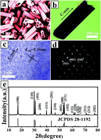
:![[thin space (1/6-em)]](https://www.rsc.org/images/entities/char_2009.gif) 2 were selected to study their morphology, structure, and composition. Fig. 1a shows the morphology of the UCHMs-G as characterized by FE-SEM. It is seen from the FE-SEM image that a large quantity of hexagonal-prismatic microtubes with uniform sizes were clearly identified. All of the tubular structures had open ends, indicating the hollow structure of the microtubes. Fig. 1b shows the TEM image of an individual microtube. The length (L) and diameter (D) of the microtube were about 2.0 μm and 0.6 μm, respectively, resulting in an aspect ratio (L/D) of ∼3.3 (Fig. 1 and Table 1).
2 were selected to study their morphology, structure, and composition. Fig. 1a shows the morphology of the UCHMs-G as characterized by FE-SEM. It is seen from the FE-SEM image that a large quantity of hexagonal-prismatic microtubes with uniform sizes were clearly identified. All of the tubular structures had open ends, indicating the hollow structure of the microtubes. Fig. 1b shows the TEM image of an individual microtube. The length (L) and diameter (D) of the microtube were about 2.0 μm and 0.6 μm, respectively, resulting in an aspect ratio (L/D) of ∼3.3 (Fig. 1 and Table 1).
| Samples (rare earth doping ions) | Phase | Morphology | L (nm) | D (nm) | Aspect ratios (L/D) | Rare earth ions composition | |
|---|---|---|---|---|---|---|---|
| Theoretical molar ratio | Measured molar ratio | ||||||
| UCHMs-R (Y3+, Er3+, Tm3+) | Hexagonal | Hollow microtube | 1350 | 400 | 3.375 | 88![[thin space (1/6-em)]](https://www.rsc.org/images/entities/char_2009.gif) : :![[thin space (1/6-em)]](https://www.rsc.org/images/entities/char_2009.gif) 10 10![[thin space (1/6-em)]](https://www.rsc.org/images/entities/char_2009.gif) : :![[thin space (1/6-em)]](https://www.rsc.org/images/entities/char_2009.gif) 2 2 |
86.8![[thin space (1/6-em)]](https://www.rsc.org/images/entities/char_2009.gif) : :![[thin space (1/6-em)]](https://www.rsc.org/images/entities/char_2009.gif) 10.7 10.7![[thin space (1/6-em)]](https://www.rsc.org/images/entities/char_2009.gif) : :![[thin space (1/6-em)]](https://www.rsc.org/images/entities/char_2009.gif) 2.5 2.5 |
| UCHMs-G (Y3+, Yb3+, Er3+) | Hexagonal | Hollow microtube | 2000 | 600 | 3.333 | 78![[thin space (1/6-em)]](https://www.rsc.org/images/entities/char_2009.gif) : :![[thin space (1/6-em)]](https://www.rsc.org/images/entities/char_2009.gif) 20 20![[thin space (1/6-em)]](https://www.rsc.org/images/entities/char_2009.gif) : :![[thin space (1/6-em)]](https://www.rsc.org/images/entities/char_2009.gif) 2 2 |
75.2![[thin space (1/6-em)]](https://www.rsc.org/images/entities/char_2009.gif) : :![[thin space (1/6-em)]](https://www.rsc.org/images/entities/char_2009.gif) 23.3 23.3![[thin space (1/6-em)]](https://www.rsc.org/images/entities/char_2009.gif) : :![[thin space (1/6-em)]](https://www.rsc.org/images/entities/char_2009.gif) 1.5 1.5 |
| UCHMs-B (Y3+, Yb3+, Tm3+) | Hexagonal | Hollow microtube | 1900 | 560 | 3.393 | 74.7![[thin space (1/6-em)]](https://www.rsc.org/images/entities/char_2009.gif) : :![[thin space (1/6-em)]](https://www.rsc.org/images/entities/char_2009.gif) 25 25![[thin space (1/6-em)]](https://www.rsc.org/images/entities/char_2009.gif) : :![[thin space (1/6-em)]](https://www.rsc.org/images/entities/char_2009.gif) 0.3 0.3 |
75.9![[thin space (1/6-em)]](https://www.rsc.org/images/entities/char_2009.gif) : :![[thin space (1/6-em)]](https://www.rsc.org/images/entities/char_2009.gif) 23.9 23.9![[thin space (1/6-em)]](https://www.rsc.org/images/entities/char_2009.gif) : :![[thin space (1/6-em)]](https://www.rsc.org/images/entities/char_2009.gif) 0.2 0.2 |
From the symmetry of the morphology, the presence of hexagonal-prismatic microtubes implied the preferred direction of [0001] for a single tube to grow. The HRTEM image shows the high crystallinity of the obtained hexagonal-prismatic microtubes, with the interplanar distance of 0.30 nm corresponding to the (110) lattice plane of hexagonal-phase NaYF4 (β-NaYF4) (JCPDS No. 28-1192) (Fig. 1c). The selected area electron diffraction (SAED) pattern taken from the side of a microtube can be indexed as the (111), (001), and (110) planes of β-NaYF4 (space group P63/m). The ordered hexagonal diffraction spots from the SAED pattern (Fig. 1d) demonstrated that the synthesized UCHMs-G exhibited a single crystalline feature. The XRD pattern of the UCHMs-G (Fig. 1e) resembled that of the standard pattern of pure β-NaYF4 crystals (JCPDS No. 28-1192). No secondary phase was observed in the XRD pattern, revealing that Yb3+/Er3+ ions were successfully doped into the β-NaYF4 lattice. The ordered hexagonal diffraction spots in the SAED pattern, and sharp diffraction peaks in the XRD pattern collectively suggested that the synthesized UCHMs-G were pure β-NaYF4: Ln3+ single crystals with high crystallinity. A phosphor with high crystallinity was critical for anti-counterfeiting applications, as it translated into less trap centers for photon emission and exhibited high luminescence.47
The element composition of the UCHMs-G was examined by EDXS. As shown in Fig. 2b, all the elements including Na, Y, F, Yb, and Er were detected in the EDXS spectrum. The molar ratio of Y: Yb: Er was 75.2![[thin space (1/6-em)]](https://www.rsc.org/images/entities/char_2009.gif) :
:![[thin space (1/6-em)]](https://www.rsc.org/images/entities/char_2009.gif) 23.3
23.3![[thin space (1/6-em)]](https://www.rsc.org/images/entities/char_2009.gif) :
:![[thin space (1/6-em)]](https://www.rsc.org/images/entities/char_2009.gif) 1.5, close to the feeding molar ratio of 78
1.5, close to the feeding molar ratio of 78![[thin space (1/6-em)]](https://www.rsc.org/images/entities/char_2009.gif) :
:![[thin space (1/6-em)]](https://www.rsc.org/images/entities/char_2009.gif) 20
20![[thin space (1/6-em)]](https://www.rsc.org/images/entities/char_2009.gif) :
:![[thin space (1/6-em)]](https://www.rsc.org/images/entities/char_2009.gif) 2, as shown in the inset of Fig. 2b and Table 1. This confirmed that all of the rare earth metal elements were well-doped in the NaYF4 matrix. The EDXS mapping (Fig. 2c–h) further showed that all the elements including the lanthanides were homogeneously distributed inside the UCHMs-G.
2, as shown in the inset of Fig. 2b and Table 1. This confirmed that all of the rare earth metal elements were well-doped in the NaYF4 matrix. The EDXS mapping (Fig. 2c–h) further showed that all the elements including the lanthanides were homogeneously distributed inside the UCHMs-G.
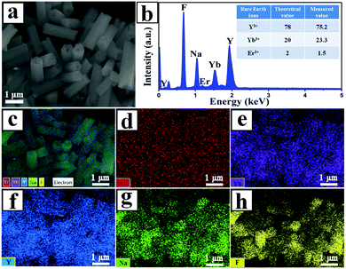 | ||
| Fig. 2 (a) FE-SEM image of the UCHMs-G sample, (b) representative results of EDXS, (c) electron image and (d–h) Er, Yb, Y, Na and F elemental maps of the UCHMs-G, respectively. | ||
During the hydrothermal process, PAA polymers with pendant carboxyl groups can chelate with Ln3+ ions and were likely to bond onto the growing crystal surface. Therefore, PAA acted as both a capping ligand and a morphology control agent in our system. To demonstrate our assumption, a controlled experiment was carried out by synthesis of NaYF4: Yb3+, Er3+ upconversion phosphors (UCPs-G) without a capping ligand under the same experimental conditions. The chemical components of the UCHMs-G and UCPs-G were characterized by FTIR. Compared with the FTIR spectrum of the UCPs-G, some additional peaks were shown in the FTIR spectrum of the UCHMs-G (Fig. S1a, ESI†). Specifically, the peak at 2929 cm−1 was attributed to the methylene asymmetric C–H stretching vibrations of the long alkyl chain of PAA, the strong band at 1720 cm−1 was assigned to the C![[double bond, length as m-dash]](https://www.rsc.org/images/entities/char_e001.gif) O stretching vibration of the –COOH group, and the bands at 1583 and 1461 cm−1 were attributed to the carboxylate asymmetric and symmetric –COO− stretching in the PAA. The FTIR spectra (Fig. S1a, ESI†) and the difference in the dispersibilities of the UCHMs-G and UCPs-G in water (Fig. S1b, ESI†) demonstrate that the PAA polymers were indeed adhered onto the surface of the synthesized UCHMs-G. The XRD pattern of the UCPs-G showed that the synthesized UCPs-G were also pure β-NaYF4: Ln3+ crystals. However, it should be pointed out that there is a large difference from each other in the relative intensities based on the (110) and (101) peaks for the UCPs-G and UCHMs-G (Fig. S1c, ESI†). This potentially suggested that the addition of the PAA capping ligand affected the possibility of different preferential growth orientations and therefore the morphology of the resultant NaYF4: Ln3+ crystals. This was confirmed by the FE-SEM characterization. The synthesized UCPs-G have an irregular shape (Fig. S1d, ESI†), while the NaYF4: Ln3+ crystals synthesized by employing PAA as a capping ligand exhibited a well-defined hollow structured microtube morphology (Fig. 1a).
O stretching vibration of the –COOH group, and the bands at 1583 and 1461 cm−1 were attributed to the carboxylate asymmetric and symmetric –COO− stretching in the PAA. The FTIR spectra (Fig. S1a, ESI†) and the difference in the dispersibilities of the UCHMs-G and UCPs-G in water (Fig. S1b, ESI†) demonstrate that the PAA polymers were indeed adhered onto the surface of the synthesized UCHMs-G. The XRD pattern of the UCPs-G showed that the synthesized UCPs-G were also pure β-NaYF4: Ln3+ crystals. However, it should be pointed out that there is a large difference from each other in the relative intensities based on the (110) and (101) peaks for the UCPs-G and UCHMs-G (Fig. S1c, ESI†). This potentially suggested that the addition of the PAA capping ligand affected the possibility of different preferential growth orientations and therefore the morphology of the resultant NaYF4: Ln3+ crystals. This was confirmed by the FE-SEM characterization. The synthesized UCPs-G have an irregular shape (Fig. S1d, ESI†), while the NaYF4: Ln3+ crystals synthesized by employing PAA as a capping ligand exhibited a well-defined hollow structured microtube morphology (Fig. 1a).
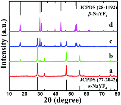
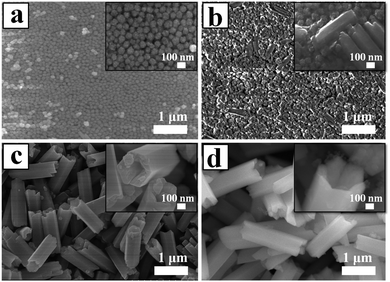
Fig. 4 shows a series of FE-SEM images that reveal the morphological evolution of the NaYF4 crystals. As shown in Fig. 4a, the initial huge number of α-NaYF4 spherical nanoparticles with an average diameter of 80 nm was formed in a short reaction time (1 h). The well-defined spherical morphology of the nanoparticles was likely attributed to the isotropic unit cell structure of α-NaYF4, resulting in an isotropic growth of the particles. It is well-known that the α-phase of NaYF4 is a metastable thermodynamic state, during which these nanoparticles would serve as seeds for the growth of β-NaYF4 hexagonal microrods via a dissolution-renucleation process under hydrothermal conditions.48 This speculation was confirmed by the appearance of a few regular and well-defined microprisms in the intermediate products synthesized at 2 h of hydrothermal reaction (Fig. 4b). The average size of the observed microprisms was ∼500 nm in length and ∼150 nm in diameter, as shown in the inset of Fig. 4b. Moreover, a large amount of nanoparticles still co-existed with the intermediate product. XRD patterns also indicated that the co-existence of two shapes resulted from the presence of the mixed crystal phase of α + β-NaYF4. The formation of a hexagonal-shaped structure was due to the anisotropic unit cell structure of β-NaYF4, which in turn induced anisotropic growth along a crystallographically reactive direction.49 Therefore, different morphologies of the NaYF4 products were attributed to α-NaYF4 (nanoparticles) and β-NaYF4 (microprisms). As the reaction time was increased to 8 h, the microprisms gradually became uniform and completely translated into microtubes, but a few small spherical solid particles were still observed. As shown in Fig. 4c, these microtubes were composed of six smooth lateral planes with reentrant grooves. The mean length and diameter of the microtubes were 1.4 μm and 0.4 μm, respectively. This suggested that the phase transition (α → β) and growth of β-NaYF4 can directly induce the morphology change of NaYF4 crystals from nanospheres to microprisms and further to microtubes.
After 24 h, the reaction yielded uniform microtubes with a 100% morphological yield and all of the tubular structures had open ends (Fig. 4d). The size of the microtubes increased from 1.4 μm to 2.0 μm in length and from 0.4 μm to 0.6 μm in diameter as the reaction time increased from 8 h to 24 h. Interestingly, the top end of the hexagonal prisms was not flat but like a crown as shown in the inset of Fig. 4d. Considering the dramatic growth of the NaYF4 microtubes in the longitudinal direction and the microtubes with reentrant grooves synthesized at 8 h reaction, the resultant microtubes adopted hollow structures and pure hexagonal phase UCHMs-G.
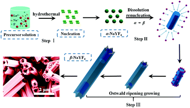
Herein we propose a possible growth mechanism for UCHMs formation. In our protocol, the synthesis of the lanthanide ion-doped NaYF4 microcrystals was developed by precipitating Na+ and Ln3+ ions with fluorides in an aqueous solution. PAA polymers with pendant carboxyl groups were chelated with Ln3+ ions and designed to regulate the reaction by binding onto the growing crystal surface. At the beginning, PAA polymers formed complexes with Ln3+ ions (i.e. Ln3+-PAA complexes) through strong coordination interactions. Under the hydrothermal condition of high temperature and high pressure, the chelating ability of the Ln3+-PAA complexes became weaker, resulting in a gradual release of Ln3+ ions. The released Ln3+ ions would react with the Na+ and F− ions in solution to generate small NaYF4 nuclei, as shown in Scheme 1, step I. Within a very short reaction time, these nuclei quickly congregated together and grew into α-NaYF4 spherical nanoparticles. However, these α-NaYF4 nanoparticles were thermodynamically unstable and then transformed into β-NaYF4 seeds. Our FE-SEM and XRD results clearly show that the phase transformation (α → β) led to a dramatic morphology change due to the different characteristic unit cell structures in their crystallographic phases. The growth of β-NaYF4 crystals generally follows the classical Ostwald ripening process in order to reduce the surface energy.50 As the reaction time increased, anisotropic growth of the crystals became dominant by rapid dissolution of the α-NaYF4 nanoparticles and release of monomers, and both effects resulted in the formation of β-NaYF4 crystals. The dissolution-renucleation process of cubic-phase nanoparticles preferentially occured at the circumferential edges of each prism microrod along the crystallographically reactive direction, resulting in the formation of β-NaYF4 microprisms with a well-defined cross section, as shown in Scheme 1, step II.
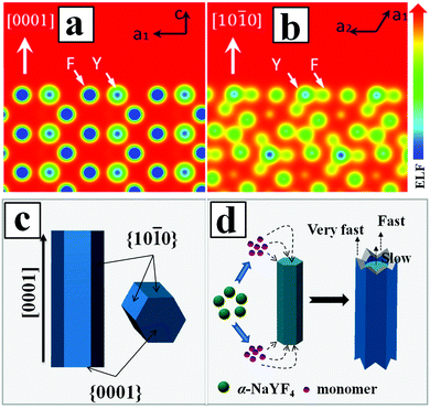
According to the general principle of crystal growth, the morphology of the crystals was correlated with the relative growth rate of different crystal facets.51 The growth velocity in different crystallographic facets of β-NaYF4 crystals were often influenced by two factors. The first factor was the coordination effect between F− and Y3+ ions. Another factor was due to the selective adhesion of PAA ligands onto the specific crystal surface that in turn affected the kinetic morphology growth.52 By calculating the electron localization function (ELF) in the NaYF4 crystal (Fig. 5a and b), we identified a stronger bonding of Y3+ with F− on the prismatic planes ({10![[1 with combining macron]](https://www.rsc.org/images/entities/char_0031_0304.gif) 0} crystal planes) than that on the top/bottom facets ({0001} crystal planes), due to the high density of Y3+ on the {10
0} crystal planes) than that on the top/bottom facets ({0001} crystal planes), due to the high density of Y3+ on the {10![[1 with combining macron]](https://www.rsc.org/images/entities/char_0031_0304.gif) 0} crystal planes as compared to the {0001} crystal planes. The high density of Y3+ also led to the higher capping ability of F− ions on the prismatic facets than that of F− ions on the top/bottom planes, which in turn decreased the average number of dangling bonds and further reduced the chemical potential of the crystal plane.53 As a result, the growth rate along the [0001] direction was much faster than that along the [10
0} crystal planes as compared to the {0001} crystal planes. The high density of Y3+ also led to the higher capping ability of F− ions on the prismatic facets than that of F− ions on the top/bottom planes, which in turn decreased the average number of dangling bonds and further reduced the chemical potential of the crystal plane.53 As a result, the growth rate along the [0001] direction was much faster than that along the [10![[1 with combining macron]](https://www.rsc.org/images/entities/char_0031_0304.gif) 0] direction. On the other hand, the high density of Y3+ on the {10
0] direction. On the other hand, the high density of Y3+ on the {10![[1 with combining macron]](https://www.rsc.org/images/entities/char_0031_0304.gif) 0} crystal planes also induced more PAA ligands to be selectively adhered onto the crystal surface and thus inhibited the growth of {10
0} crystal planes also induced more PAA ligands to be selectively adhered onto the crystal surface and thus inhibited the growth of {10![[1 with combining macron]](https://www.rsc.org/images/entities/char_0031_0304.gif) 0} crystal planes along the transverse direction. Meanwhile, the less adsorption of PAA ligands on the {0001} crystal planes resulted in a relatively faster growth rate along the [0001] direction than that along the [10
0} crystal planes along the transverse direction. Meanwhile, the less adsorption of PAA ligands on the {0001} crystal planes resulted in a relatively faster growth rate along the [0001] direction than that along the [10![[1 with combining macron]](https://www.rsc.org/images/entities/char_0031_0304.gif) 0.] direction. Additionally, the growth of β-NaYF4 microprisms consumed the vicinal monomers near rod-like NaYF4 at the expense of the dissolution of nearby cubic α-NaYF4 spherical-like particles. The dissolved monomers from cubic α-NaYF4 will first be in contact with the extending top corner of the rods, followed by the rim and center area, leading to different growth rates at the top corner, rim, and center in the {0001} facet that eventually produced a hollow structure of NaYF4 crystals with crown-like top ends, as shown in Fig. 5d.
0.] direction. Additionally, the growth of β-NaYF4 microprisms consumed the vicinal monomers near rod-like NaYF4 at the expense of the dissolution of nearby cubic α-NaYF4 spherical-like particles. The dissolved monomers from cubic α-NaYF4 will first be in contact with the extending top corner of the rods, followed by the rim and center area, leading to different growth rates at the top corner, rim, and center in the {0001} facet that eventually produced a hollow structure of NaYF4 crystals with crown-like top ends, as shown in Fig. 5d.
![[thin space (1/6-em)]](https://www.rsc.org/images/entities/char_2009.gif) :
:![[thin space (1/6-em)]](https://www.rsc.org/images/entities/char_2009.gif) 10.7
10.7![[thin space (1/6-em)]](https://www.rsc.org/images/entities/char_2009.gif) :
:![[thin space (1/6-em)]](https://www.rsc.org/images/entities/char_2009.gif) 2.5 (Y3+
2.5 (Y3+![[thin space (1/6-em)]](https://www.rsc.org/images/entities/char_2009.gif) :
:![[thin space (1/6-em)]](https://www.rsc.org/images/entities/char_2009.gif) Er3+
Er3+![[thin space (1/6-em)]](https://www.rsc.org/images/entities/char_2009.gif) :
:![[thin space (1/6-em)]](https://www.rsc.org/images/entities/char_2009.gif) Tm3+) and 75.9
Tm3+) and 75.9![[thin space (1/6-em)]](https://www.rsc.org/images/entities/char_2009.gif) :
:![[thin space (1/6-em)]](https://www.rsc.org/images/entities/char_2009.gif) 23.9
23.9![[thin space (1/6-em)]](https://www.rsc.org/images/entities/char_2009.gif) :
:![[thin space (1/6-em)]](https://www.rsc.org/images/entities/char_2009.gif) 0.2 (Y3+
0.2 (Y3+![[thin space (1/6-em)]](https://www.rsc.org/images/entities/char_2009.gif) :
:![[thin space (1/6-em)]](https://www.rsc.org/images/entities/char_2009.gif) Yb3+
Yb3+![[thin space (1/6-em)]](https://www.rsc.org/images/entities/char_2009.gif) :
:![[thin space (1/6-em)]](https://www.rsc.org/images/entities/char_2009.gif) Tm3+), respectively, close to the feeding molar ratios in Table 1.
Tm3+), respectively, close to the feeding molar ratios in Table 1.
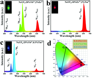
The upconversion emission spectra of UCHMs-R and UCHMs-B are shown in Fig. 6b and c, respectively. In Fig. 6b, the major peak position of UCHMs-R is located at 656 nm of red color, corresponding to the transition of 4F9/2 → 4I15/2 of Er3+. Thus, a bright red upconversion emission was observed from the dispersion of the as-prepared UCHMs-R under irradiation of a 980 nm laser (Fig. 6b, inset). For the UCHMs-B, divergent blue color emission peaks were located at 450 nm and 475 nm, while a red color emission peak was located at 644 nm. These three peaks corresponded to the 1D2 → 3F4, 1G4 → 3H6, and 1G4 → 3F4 transitions of Tm3+, respectively. Since the intensity of the blue emission peaks was significantly higher than that of the red peak, the UCHMs-B showed a blue color under the irradiation of a 980 nm laser (Fig. 6c, inset).
Furthermore, the fluorescence property of the RGB UCHMs in the solid state was examined using a confocal fluorescence microscope. As shown in Fig. S3 (ESI†), a high contrast, hypersensitive red, green, and blue fluorescent image of RGB UCHMs was observed at an excitation wavelength of 980 nm without auto-fluorescence from the background. The energy level diagrams of the Er3+/Tm3+, Yb3+/Er3+ and Yb3+/Tm3+ co-doped NaYF4 lattice are shown in Fig. S4 (ESI†). The upconversion fluorescence of the RGB UCHMs was marked in the CIE color coordinates and is shown in Fig. 6d. The CIE color coordinates of the UCHMs-R, UCHMs-G, and UCHMs-B were (0.654, 0.321), (0.271, 0.701) and (0.136, 0.083), respectively. It can be seen that the triangle composed by the positions of the RGB UCHMs materials can cover almost half the region of the chromaticity diagram, which means that a variety of colors (including white) can be obtained based on the RGB UCHMs materials. In addition, it was demonstrated that all of the UCHMs exhibited stronger upconversion fluorescence than the upconversion nanoparticles (UCNPs) synthesized by an oleic acid assisted thermal decomposition method (Fig. S5, ESI†). This was due to the high crystallinity and the low density of surface quenching centers in the UCHMs microcrystals.55 Overall, the hydrophilic property, unique morphology, strong upconversion fluorescence intensity and tunable fluorescence color made the UCHMs good fluorescent materials for inkjet printing for anti-counterfeiting applications.
2.2. Inkjet printing of UCHMs for anti-counterfeiting
While electronic communication has become an integral part of our daily life, paper still plays an indispensable role in information storage, retrieval, and management systems. Many important documents, including passports, checks, and bonds, are paper-based. So, information encryption on paper is still a challenging task for many applications.56,57 In this work, the as-prepared RGB UCHMs were dispersed in a solvent mixture of ethanol, water, and glycerol to form RGB fluorescent inks for anti-counterfeiting applications.To ensure that the inks work stably in the inkjet printer, we tuned the ink properties by evaluating the printing performance (i.e., dynamic viscosity and surface tension). Here we discuss the preparation of the UCHMs-G ink as a typical example. By fixing the weight ratio of UCHMs-G (0.2 wt%) and changing the weight ratio of deionized water, ethanol, and glycerol, a series of UCHMs-G inks were formulated (sample Ink1–Ink6). The detailed parameters of the preparation of Ink1–Ink6 are shown in Table S1 (ESI†). The properties of different UCHMs-G ink samples were characterized by evaluating the dynamic viscosity and surface tension, and the results are summarized in Table S2 (ESI†). Generally, the dynamic viscosity of ink can affect its flow in the cartridge and through the nozzle. High viscosity ink may cause the nozzle to clog, while low viscosity ink may cause damped oscillation and infiltration resulting in loss of print accuracy and luminescence intensity. In addition, an appropriate surface tension of ink helps in keeping a relatively small contact angle over the substrates, which increases the coverage area for a single drop of ink to form patterns with good uniformity under certain dots per inch (DPI) of a printer. The preferred dynamic viscosity and surface tension of ink for the inkjet printer may vary within a specific range at room temperature: the dynamic viscosity varies from 1 to 5 mPa s while the surface tension varies from 30 to 60 mN m−1.34,58 Based on the results in Table S2 (ESI†), we chose Ink5 as the optimized ink, where the dynamic viscosity and surface tension are 3.432 mPa s and 33.404 mN m−1, respectively. By keeping the mass ratio of UCHMs-R (1.0 wt%) and UCHMs-B (0.5 wt%), respectively, another two upconversion fluorescent inks with proper dynamic viscosity and surface tension are prepared (Table S3, ESI†).
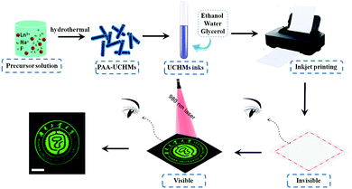
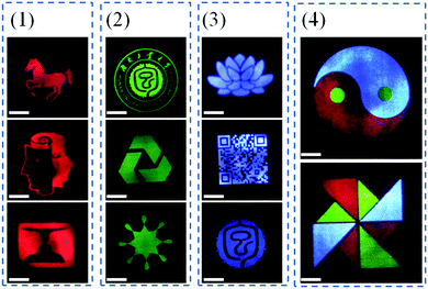
Multicolored and designable patterns were printed on the common A4 paper substrate using the as-obtained RGB fluorescent inks by inkjet printing technology. Scheme 2 shows the inkjet printing procedure of the UCHMs fluorescent inks on paper. During the first step, patterns were generated by independent deposition of RGB fluorescent inks on the A4 paper substrate. As shown in Fig. 7, under 980 nm light excitation, different printed patterns with different colors appeared on the paper with very fine details, including red patterns (horse, human face, and goblet patterns in Fig. 7, group 1), green patterns (“Hunan University of Technology” logo, triangle circle, and the star patterns in Fig. 7, group 2), and blue patterns (lotus, QR code, and the Chinese character of  which is the school badge of Hunan University of Technology in Fig. 7, group 3). Subsequently, the three-primary-color inks were printed as isolated and overlapping features to produce a more complicated images. As shown in (Fig. 7, group 4), colorful patterns of “taichi” diagram and windmill, which simultaneously emit distinct red, green and blue upconversion luminescence, can be observed under 980 nm light excitation. These images clearly indicate that the UCHMs ink-based anti-counterfeiting labels possessed excellent hiddenness and security, and could be used as a smart encryption for anti-counterfeiting and security applications.
3. Conclusions
Security of optical information is of great importance in modern society. In this work, novel β-NaYF4 UCHMs doped with different lanthanide ions (Ln3+ = Er3+/Tm3+, Yb3+/Er3+, and Yb3+/Tm3+) were designed to produce red-green-blue luminescence using a facile hydrothermal process employing PAA as a stabilizing agent and ligand. The preparation of all the intermediates and the final products was simple and with high yields. All of the β-NaYF4: Ln3+ UCHMs possessed well-defined structures and strong upconversion fluorescence. The formation of the NaYF4 UCHMs involved a phase transition from pure cubic-phase to mixed cubic/hexagonal-phases to pure hexagonal-phase, correlating with morphology changes from spherical nanoparticles to short microprisms, and ultimately to hollow microtubes. Both the phase transitions and morphology changes were attributed to the classical Ostwald ripening process and different growth rates of different crystal facets. More importantly, upon doping of UCHMs with different lanthanide ions and tailoring the molar ratio of the doped lanthanide ions, three-primary-color (RGB) UCHMs were prepared. The resulting RGB UCHMs can be dispersed in a solvent mixture of ethanol, water, and glycerol to obtain different fluorescent inks. We further demonstrated that the RGB UCHMs inks can be used to print hidden optical images on regular paper using inkjet printing technology. These hidden images were completely invisible at standard lighting conditions, but became visible with multi-luminescent colors at 980 nm light excitation. We envision that the environment-friendly UCHMs fluorescent inks, integrating their simple fabrication process, rapid inkjet printing, and difficulty for encryption, have enormous potential for anti-counterfeiting, multilevel image encryption, and background-free image reconstruction.Conflicts of interest
There are no conflicts to declare.Acknowledgements
The financial support by National Key Research and Development Program of China (2018YFD0400705), National Science Foundation of China (21501056 and 21705043), the National Science Foundation for Post-Doctoral Scientists of China (2018M632981), and the Science Foundation of Hunan Province (218JJ3115 and 218JJ3117) is gratefully acknowledged.Notes and references
- T. Kelesidis, I. Kelesidis, P. I. Rafailidis and M. E. Falagas, J. Antimicrob. Chemother., 2007, 60, 214–236 CrossRef PubMed.
- B. Yoon, J. Lee, I. S. Park, S. Jeon, J. Lee and J. M. Kim, J. Mater. Chem. C, 2013, 1, 2388–2403 RSC.
- K. Pawan, S. Satbir and K. G. Bipin, Nanoscale, 2016, 8, 14297–14340 RSC.
- A. Mitrokotsa, M. R. Rieback and A. S. Tanenbaum, Inf. Syst. Front., 2009, 12, 491–505 CrossRef.
- T. Zhang, L. Fu, Z. Chen, Y. Cui and X. Liu, Prog. Org. Coat., 2016, 100, 100–104 CrossRef.
- H. Peng, S. Bi, M. Ni, X. Xie, Y. Liao, X. Zhou, Z. Xue, J. Zhu, Y. Wei, C. N. Bowman and Y. W. Mai, J. Am. Chem. Soc., 2014, 136, 8855–8858 CrossRef PubMed.
- W. Yao, Q. Tian, J. Liu, Q. Xue, M. Li, L. Liu, Q. Lu and W. Wu, Nanoscale, 2017, 9, 15982–15989 RSC.
- J. Andres, R. D. Hersch, J. E. Moser and A. S. Chauvin, Adv. Funct. Mater., 2014, 24, 5029–5036 CrossRef.
- Z. Xu, D. Gonzalez-Abradelo, J. Li, C. A. Strassert, B. J. Ravoo and D. S. Guo, Mater. Chem. Front., 2017, 1, 1847–1852 RSC.
- X. Wu, H. Liu, J. Liu, K. N. Haley, J. A. Treadway, J. P. Larson, N. Ge, F. Peale and M. P. Bruchez, Nat. Biotechnol., 2003, 21, 41–46 CrossRef PubMed.
- M. You, M. Lin, S. Wang, X. Wang, G. Zhang, Y. Hong, Y. Dong, G. Jin and F. Xu, Nanoscale, 2016, 8, 10096–10104 RSC.
- A. H. Mady, M. L. Baynosa, D. Tuma and J. J. Shim, Appl. Catal., B, 2017, 203, 416–427 CrossRef.
- J. Liu, Y. Zhuang, L. Wang, T. Zhou, N. Hirosaki and R. J. Xie, ACS Appl. Mater. Interfaces, 2018, 10, 1802–1809 CrossRef PubMed.
- X. Liu, R. Deng, Y. Zhang, Y. Wang, H. Chang, L. Huang and X. Liu, Chem. Soc. Rev., 2015, 44, 1479–1508 RSC.
- F. Wang and X. Liu, Acc. Chem. Res., 2014, 47, 1378–1385 CrossRef PubMed.
- J. Cheng, E. H. Hill, Y. Zheng, T. He and Y. Liu, Mater. Chem. Front., 2018, 2, 662–678 RSC.
- M. You, Z. Li, P. Zhang, D. Bai, M. Lin and F. Xu, in Handbook of Immunoassay Technologies, ed. S. K. Vashist and J. H. T. Luong, Academic Press, 2018, pp. 273–304 DOI:10.1016/B978-0-12-811762-0.00011-6.
- B. Jin, S. Wang, M. Lin, Y. Jin, S. Zhang, X. Cui, Y. Gong, A. Li, F. Xu and T. J. Lu, Biosens. Bioelectron., 2017, 90, 525–533 CrossRef PubMed.
- B. Zhu, B. Qian, Y. Liu, C. Xu, C. Liu, Q. Chen, J. Zhou, X. Liu and J. Qiu, NPG Asia Mater., 2017, 9, e394 CrossRef.
- M. Hu, D. Ma, C. Liu, J. Wang, Z. Zhang and L. Meng, J. Mater. Chem. C, 2016, 4, 6975–6981 RSC.
- A. Baride, J. M. Merug, C. Douma, D. Langerman, G. Crawford, J. J. Kellar, W. M. Crossb and P. S. May, RSC Adv., 2015, 5, 101338–101346 RSC.
- G. P. Darshan, H. B. Premkumar, H. Nagabhushana, S. C. Sharma, S. C. Prashantha, H. P. Nagaswarup and B. D. Prasad, Dyes Pigm., 2016, 131, 268–281 CrossRef.
- B. Zhou, B. Shi, D. Jin and X. Liu, Nat. Nanotechnol., 2015, 10, 924–936 CrossRef PubMed.
- X. Sang, W. Chen, P. Chen, X. Liu and J. Qiu, J. Mater. Chem. C, 2015, 3, 9089–9094 RSC.
- J. C. Boyer, N. J. J. Johnson and F. C. J. M. v. Veggel, Chem. Mater., 2009, 21, 2010–2012 CrossRef.
- R. Chai, H. Lian, Z. Hou, C. Zhang, C. Peng and J. Lin, J. Phys. Chem. C, 2010, 114, 610–616 CrossRef.
- H. Tan, S. Xie, J. Xu, N. Li, C. Zhang, L. Xu and J. Zheng, Sci. Adv. Mater., 2017, 9, 2223–2233 Search PubMed.
- Y. Liu, Y. H. Lee, Q. Zhang, Y. Cui and X. Y. Ling, J. Mater. Chem. C, 2016, 4, 4312–4319 RSC.
- M. Ecker and T. Pretsch, RSC Adv., 2014, 4, 286–292 RSC.
- M. Li, W. Yao, J. Liu, Q. Tian, L. Liu, J. Ding, Q. Xue, Q. Lu and W. Wu, J. Mater. Chem. C, 2017, 5, 6512–6520 RSC.
- L. He, L. Xia, Y. Yang, Q. Zheng, N. Jiang, C. Xu, Y. Liu and D. Lin, Mater. Res. Bull., 2017, 95, 483–490 CrossRef.
- T. Blumenthal, J. Meruga, P. Stanley May, J. Kellar, W. Cross, K. Ankireddy, S. Vunnam and Q. N. Luu, Nanotechnology, 2012, 23, 185305–185312 CrossRef PubMed.
- J. M. Meruga, A. Baride, W. Cross, J. J. Kellar and P. S. May, J. Mater. Chem. C, 2014, 2, 2221–2227 RSC.
- M. You, J. Zhong, Y. Hong, Z. Duan, M. Lin and F. Xu, Nanoscale, 2015, 7, 4423–4431 RSC.
- Q. Ma, J. Wang, Z. Li, D. Wang, X. Hu, Y. Xu and Q. Yuan, Inorg. Chem. Front., 2017, 4, 1166–1172 RSC.
- L. L. da Luz, R. Milani, J. F. Felix, I. R. Ribeiro, M. Talhavini, B. A. Neto, J. Chojnacki, M. O. Rodrigues and S. A. Junior, ACS Appl. Mater. Interfaces, 2015, 7, 27115–27123 CrossRef PubMed.
- W. Gao, H. Zheng, Q. Han, E. He and R. Wang, CrystEngComm, 2014, 16, 6697–6706 RSC.
- G. Bühler and C. Feldmann, Appl. Phys. A: Mater. Sci. Process., 2007, 87, 631–636 CrossRef.
- M. Ding, D. Chen, S. Yin, Z. Ji, J. Zhong, Y. Ni, C. Lu and Z. Xu, Sci. Rep., 2015, 5, 12745–12757 CrossRef PubMed.
- M. Lin, Y. Zhao, M. Liu, M. Qiu, Y. Dong, Z. Duan, Y. Li, B. Pingguan-Murphy, T. Lu and F. Xu, J. Mater. Chem. C, 2014, 2, 3671–3676 RSC.
- C. Li, Z. Quan, P. Yang, S. Huang, H. Lian and J. Lin, J. Phys. Chem. C, 2008, 112, 13395–13404 CrossRef.
- Y. Su, L. Li and G. Li, Cryst. Growth Des., 2008, 8, 2678–2683 CrossRef.
- B. Chen, W. Kong, Y. Liu, Y. Lu, M. Li, X. Qiao, X. Fan and F. Wang, Angew. Chem., Int. Ed., 2017, 56, 10383–10387 CrossRef PubMed.
- D. Gao, D. Tian, X. Zhang and W. Gao, Sci. Rep., 2016, 6, 22433–22442 CrossRef PubMed.
- B. Chen, T. Sun, X. Qiao, X. Fan and F. Wang, Adv. Opt. Mater., 2015, 3, 1577–1581 CrossRef.
- S. Zeng, G. Ren, W. Li, C. Xu and Q. Yang, J. Phys. Chem. C, 2010, 114, 10750–10754 CrossRef.
- F. Shi, J. Wang, D. Zhang, G. Qin and W. Qin, J. Mater. Chem., 2011, 21, 13413–13421 RSC.
- X. Guo, P. Li, S. Yin and W. Qin, J. Fluorine Chem., 2017, 200, 91–95 CrossRef.
- S. Ullah, C. Hazra, E. P. Ferreira-Neto, T. C. Silva, U. P. Rodrigues-Filho and S. J. L. Ribeiro, CrystEngComm, 2017, 19, 3465–3475 RSC.
- M. Ding, Y. Li, D. Chen, H. Lu, J. Xi and Z. Ji, J. Alloys Compd., 2016, 658, 952–960 CrossRef.
- M. K. Singh and A. Banerjee, Cryst. Growth Des., 2013, 13, 2413–2425 CrossRef.
- Y. Yin and A. P. Alivisatos, Nature, 2005, 437, 664–670 CrossRef PubMed.
- X. Liang, X. Wang, J. Zhuang, Q. Peng and Y. Li, Adv. Funct. Mater., 2007, 17, 2757–2765 CrossRef.
- H. Dong, L. D. Sun and C. H. Yan, Chem. Soc. Rev., 2015, 44, 1608–1634 RSC.
- F. Wang, J. Wang and X. Liu, Angew. Chem., Int. Ed., 2010, 49, 7456–7460 CrossRef PubMed.
- W. Jeong, M. I. Khazi, D. H. Park, Y. S. Jung and J.-M. Kim, Adv. Funct. Mater., 2016, 26, 5230–5238 CrossRef.
- W. Wang, N. Xie, L. He and Y. Yin, Nat. Commun., 2014, 5, 5459–5465 CrossRef PubMed.
- B. J. de Gans and U. S. Schubert, Macromol. Rapid Commun., 2003, 24, 659–666 CrossRef.
Footnotes |
| † Electronic supplementary information (ESI) available. See DOI: 10.1039/c8qm00278a |
| ‡ Joint first authors, contributed equally to this work. |
| This journal is © the Partner Organisations 2018 |

