Benzyl and fluorinated benzyl side chains for perylene diimide non-fullerene acceptors†‡
Maryam
Nazari
 a,
Mark
Martell
a,
Thomas A.
Welsh
a,
Mark
Martell
a,
Thomas A.
Welsh
 a,
Owen
Melville
b,
Zhe
Li
c,
Jonathan
Cann
a,
Edward
Cieplechowicz
a,
Owen
Melville
b,
Zhe
Li
c,
Jonathan
Cann
a,
Edward
Cieplechowicz
 a,
Yingping
Zou
 c,
Benoit H.
Lessard
 b and
Gregory C.
Welch
 *a
*a
aDepartment of Chemistry, University of Calgary, 2500 University Drive NW Calgary, Alberta T2N 1N4, Canada. E-mail: gregory.welch@ucalgary.ca
bDepartment of Chemical and Biological Engineering, University of Ottawa, 161 Louis Pasteur, Ottawa, Ontario, K1N 6N5, Canada
cCollege of Chemistry and Chemical Engineering, Central South University, Changsha 410083, China
First published on 11th October 2018
Abstract
The synthesis and characterization of three N-annulated perylene diimide dimers with benzyl based side-chains is reported. Benzyl, 4-fluorobenzyl, and pentafluorobenzyl groups are used as side chains at the pyrrolic N-atom position of the N-annulated perylene diimide chromophore. All three compounds were used as non-fullerene acceptors in polymer based organic solar cells. Power conversion efficiencies upwards of 5.8% were achieved for both benzyl and 4-fluorobenzyl substituted acceptors, with different donor polymers.
Perylene diimide (PDI) based molecules have emerged as one of the best classes of non-fullerene acceptors (NFA) used in bulk heterojunction (BHJ) organic photovoltaics (OPV).1–6 For single junction OPVs, the best power conversion efficiency (PCE) has reached 7–9%7–10 for polymer solar cells using dimeric PDI NFAs and 8–10% for polymer solar cells using tetrameric PDI NFAs.11,12 In parallel PDI based polymers have emerged as promising NFAs.13,14
The material properties of these NFAs are dominated by the PDI chromophore. All the NFAs exhibit strong visible light absorption from 400–600 nm, low lying LUMO energy levels at ∼−3.6 to −3.9 eV, and high photochemical and thermal stability.15 The PDI NFAs are most often paired with narrow band gap polymer donors. Several strategies to tune the properties of PDI NFAs are ring fusion,11,16,17 core substitution,18–22 and annulation8,10,23–25 at the bay position.
A material-based strategy to increase the performance of OPVs that has not been widely employed for PDI NFAs is the so-called ‘side-chain engineering’.26 Branched alkyl chains (3-pentyl or 6-undecyl) are typically used at both imide positions and seemingly only impact solubility parameters. There are several reports of alkoxy based side chains being installed at the bay positions,27,28 but most PDI NFAs are modified with π-conjugated substituents.
Our group has been investigating N-annulated PDIs.23,29,30N-Annulation at the bay position allows for an extra site of tunability, increases solubility, and decreases the molecule's electron affinity leading to higher lying LUMO levels and higher open circuit voltages (VOC) in OPV devices.23,31N-Annulated PDI dimers with alkyl chains at the pyrrolic N-position have been used to fabricate OPVs with PCEs from 5–7%.32 Side-chain engineering revealed that long and branched side chains give the best solubility and OPV performance.33 Thus, the N-annulated PDI is an important molecule as it allows for rapid side-chain engineering via simple SN2 chemistry.
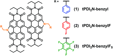
Herein we show that benzyl-based moieties are effective side-chains for the development of new PDI NFAs that can give good device performance. The target structures, shown in Fig. 1, incorporate benzyl, 4-fluorobenzyl, and pentafluorobenzyl side-chains. CH and CF benzyl chains were selected as they should lead to different intermolecular interactions as compared to alkyl chains, with the possibility of increased π–π interactions, and different electronic influences on the dimeric PDI core.
The compounds tPDI2N-benzyl (1), tPDI2N-benzylF (2) and, tPDI2N-benzylF5 (3) were synthesized following our previously reported procedures.23 Each compound was identified using 1H and 13C NMR spectroscopy, mass spectrometry, and elemental analysis. Full details can be found in the ESI.‡ Each compound was thermally stable up to ∼410 °C, with the first mass loss attributed to the decomposition of the imide groups, thus indicating that benzyl-based moieties are not the weak points of the molecules.
The electrochemical properties of 1, 2, and 3 were determined by cyclic voltammetry supported by differential pulse voltammetry measurements. Each compound exhibits four reversible reduction events and one quasi-reversible oxidation event, typical for N-annulated PDI dimers (Fig. S28, ESI‡). E1/2 values and estimated reduction/oxidation onsets are given in Table 1. Compound 1 has similar energetics to the related alkyl chain derivatives.22,33 The addition of 2 F-atoms (2) slightly lowers the reduction potential but has little impact on the oxidation. The addition of 10 F-atoms (3) further lowers the reduction potential but also serves to alter the oxidation by increasing it. This is expected as the C6F5 groups are considerably more electron withdrawing than the C6H5 groups. The trends were confirmed by modelling the structures using density functional theory calculations (see Fig. S31, ESI‡). As a general comparison to the ‘alkyl chain’ derivatives, the benzyl chain gives similar electronic properties while the fluorinated benzyl chains serve to stabilize the frontier molecular orbital energy levels.
| E 1/2 (V) | E 1/2 (V) | E HOMO IP (eV) | E LUMO EA (eV) | ε solc | λ max sol/film | |
|---|---|---|---|---|---|---|
| a All data referenced to the Fc/Fc+ redox couple. b The ionization potential (IP) and electron affinity (EA), commonly correlated to the HOMO and LUMO energy levels were determined from the first E1/2 values, see ESI. c CH2Cl2. | ||||||
| 1 | −1.24, −1.35 | 1.16 | −5.96 | −3.56 | 117![[thin space (1/6-em)]](https://www.rsc.org/images/entities/char_2009.gif) 000 000 |
532/533 |
| −1.56, −1.66 | ||||||
| 2 | −1.22, −1.30 | 1.16 | −5.96 | −3.58 | 120![[thin space (1/6-em)]](https://www.rsc.org/images/entities/char_2009.gif) 000 000 |
530/533 |
| −1.52, −1.64 | ||||||
| 3 | −1.19, −1.28 | 1.23 | −6.03 | −3.61 | 124![[thin space (1/6-em)]](https://www.rsc.org/images/entities/char_2009.gif) 000 000 |
525/528 |
| −1.49, −1.61 | ||||||
The optical properties were determined using UV/vis spectroscopy. Fig. 2 shows the optical absorption spectra of 1–3 in solution and as spun-cast films. All compounds have typical optical profiles for PDI based materials in solution with a strong absorption band from 400–550 nm (ε at λmax ∼ 120![[thin space (1/6-em)]](https://www.rsc.org/images/entities/char_2009.gif) 000 M−1 cm−1) with three characteristic vibrionic peaks for the 0–0, 0–1, and 0–2 transitions (low to high energy). While the spectra for 1 and 2 are nearly identical, that of 3 is slightly blue shifted, a consequence of the electron withdrawing C6F5 groups having a larger impact on the HOMO level (i.e. lowering the HOMO energy level), as compared to 1 and 2, widening the band gap, again confirmed by DFT calculations (Fig. S31, ESI‡). A transition from solution to thin-film shows a slight-red shift and broadening of the spectra for 1 and 2, in addition to an increase in the intensity of 0–1 transition (λ = 495 nm), indicative of molecular aggregation. There is less of a change for compound 3 which implies a different solid-state organization. The less pronounced 0–1 transition (λ = 491 nm) for 3 also suggests a lower degree of organization within the film.
000 M−1 cm−1) with three characteristic vibrionic peaks for the 0–0, 0–1, and 0–2 transitions (low to high energy). While the spectra for 1 and 2 are nearly identical, that of 3 is slightly blue shifted, a consequence of the electron withdrawing C6F5 groups having a larger impact on the HOMO level (i.e. lowering the HOMO energy level), as compared to 1 and 2, widening the band gap, again confirmed by DFT calculations (Fig. S31, ESI‡). A transition from solution to thin-film shows a slight-red shift and broadening of the spectra for 1 and 2, in addition to an increase in the intensity of 0–1 transition (λ = 495 nm), indicative of molecular aggregation. There is less of a change for compound 3 which implies a different solid-state organization. The less pronounced 0–1 transition (λ = 491 nm) for 3 also suggests a lower degree of organization within the film.
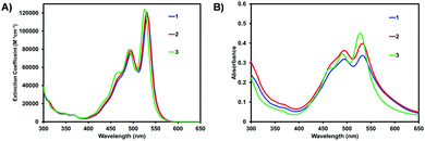 | ||
| Fig. 2 Optical absorption spectra of PDI materials 1–3 in (A) CHCl3 solution and (B) as spun-cast films. Films were cast from 10 mg mL−1 CHCl3 solutions and measured as-cast. Raw data is shown. Normalized data shown in Fig. S30 (ESI‡). | ||
Previously we have shown that thermally annealed (TA) thin-films of PDI materials can positively influence device performance. Specifically, TA at 180 °C resulted in an increase in both electron mobility and solar cell performance.29 Neat films of 1–3 were investigated ‘as-cast’ and after TA at 180 °C (Fig. S32, ESI‡). The UV/vis spectra of films of 1 and 2 showed a more pronounced 0–0 peak after TA, while that of 3 showed little change. No obvious crystallization was observed with the POM images being featureless, but the atomic force microscopy (AFM) images (Fig. 3) showed a clear roughening of the films and the formation of fibril like domains after TA. The change is most pronounced for 1 and 2.
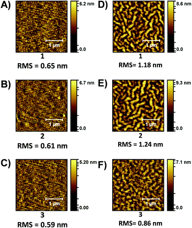 | ||
| Fig. 3 AFM topology (2.5 × 2.5 μm) images of PDI films. ‘As-cast”: (A) 1, (B) 2, (C) 3. Thermally annealed 180 °C: (D) 1, (E) 2, (F) 3. | ||
To evaluate the charge transport properties of PDI materials 1–3, bottom-gate, bottom contact (BGBC) organic thin-film transistors (OTFT) were fabricated with results summarized in Table 2. All devices were N-type in a vacuum, with electron field-effect mobility ranging between 7.2 × 10⁻⁶ and 19.8 × 10⁻⁶ cm2 V−1 s−1 for devices fabricated without thermal annealing. These values exceeded comparable results from three previously reported dimeric PDI derivatives,29 potentially due to the additional π–π stacking afforded by the benzyl substituents. Upon thermal annealing, devices using 1 and 3 improved mildly, while devices using 2 improved significantly, with electron field-effect mobility increasing by an order of magnitude to 81.8 × 10⁻⁶ cm2 V−1 s−1.
| 1 | 1 | 2 | 2 | 3 | 3 | |
|---|---|---|---|---|---|---|
| a Thermally annealed films at 180 °C. | ||||||
| μ avg (× 10−6 cm2 V−1 s−1) | 19.8 | 23.7 | 7.2 | 81.8 | 13.9 | 19.2 |
| μ max (× 10−6 cm2 V−1 s−1) | 25.8 | 25.5 | 8.9 | 86.7 | 15.9 | 21.2 |
| V T (V) | 15–18 | 20–22 | 28–29 | 15–17 | 15–16 | 15–17 |
| I on/off | 102−3 | 103 | 102 | 103 | 102−3 | 103 |
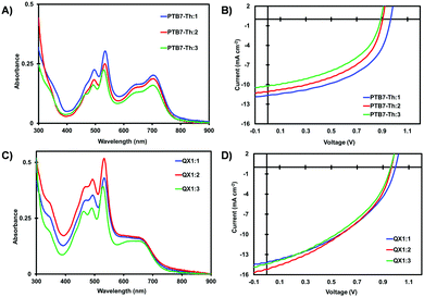
All three PDI materials were evaluated as non-fullerene acceptors in polymer-based bulk-heterojunction (BHJ) organic solar cells (OSCs). Following a standard procedure in our lab, all solar cells were fabricated using an inverted device architecture (ITO/ZnO/BHJ/MoOx/Ag).34 Recognizing the importance of donor polymer selection, two polymers were used: PTB7-Th35 and TTFQx-T136 (QX1), both shown to give high PCE OSCs when paired with PDI acceptors in our labs.32,33 Active layers were processed under the best conditions previously disclosed.23,29 All devices were tested in air. Current–voltage curves are shown in Fig. 4. Full details are found in the ESI.‡
The optical absorption spectra of PTB7-Th:PDI films (Fig. 4A) exhibit absorption from 400–800 nm whereas those of QX1![[thin space (1/6-em)]](https://www.rsc.org/images/entities/char_2009.gif) :
:![[thin space (1/6-em)]](https://www.rsc.org/images/entities/char_2009.gif) PDI films (Fig. 4C) exhibit absorption from 400–750 nm. The low energy band in each spectrum is attributed to the polymer donor, with QX1 being slightly blue shifted to PTB7-Th owing to a deeper HOMO energy level (Fig. S35, ESI‡). Of the six blended films, those using 3 as the acceptor showed lower overall absorption intensity. For all films, the emission of the polymer donor was efficiently quenched by the PDI acceptor (Fig. S36 and S37, ESI‡).
PDI films (Fig. 4C) exhibit absorption from 400–750 nm. The low energy band in each spectrum is attributed to the polymer donor, with QX1 being slightly blue shifted to PTB7-Th owing to a deeper HOMO energy level (Fig. S35, ESI‡). Of the six blended films, those using 3 as the acceptor showed lower overall absorption intensity. For all films, the emission of the polymer donor was efficiently quenched by the PDI acceptor (Fig. S36 and S37, ESI‡).
Comparing the PTB7-Th based devices, those with a PTB7-Th:1 active layer gave the best performance with champion PCE of 5.69% with a VOC of 0.96 V, a JSC of 11.7 mA cm−2, and FF of 51%. PTB7-Th:2 based devices gave the best PCE of 4.89% with a VOC of 0.90 V, a JSC of 11.0 mA cm−2, and FF of 49%. Average PCE was 4.88% and 4.17% for 1 and 2 based OSCs. The drop in PCE is attributed to the lower VOC, a consequence of the F-atoms which served to lower the reduction potential. PTB7-Th:3 based devices had the best and average PCE of 4.21% and 3.86%, respectively, with a notable decrease in all parameters, compared to OSCs using 1 and 2 as NFAs. The systematic decrease in VOC when using acceptors 1 to 2 to 3 is consistent with the increasing number of F-atoms which serve to stabilize the LUMO energy levels. The device performance of PTB7-Th:1 based OSCs is slightly higher than that of related devices using alkyl based N-annulated PDIs reported by our group31,33 and recently that of Huang and co-workers,25 highlighting the potential of the benzyl sidechain (Table 3).
| BHJ | V OC (V) | J SC (mA cm−2) | FF (%) | PCE (%) |
|---|---|---|---|---|
Device architecture: ITO/ZnO/BHJ/MoOx/Ag. PTB7-Th:1–3 BHJs processed from 1![[thin space (1/6-em)]](https://www.rsc.org/images/entities/char_2009.gif) : :![[thin space (1/6-em)]](https://www.rsc.org/images/entities/char_2009.gif) 1 C6H5Cl solutions. QX1:1–3 BHJs processed from 4 1 C6H5Cl solutions. QX1:1–3 BHJs processed from 4![[thin space (1/6-em)]](https://www.rsc.org/images/entities/char_2009.gif) : :![[thin space (1/6-em)]](https://www.rsc.org/images/entities/char_2009.gif) 6 2Me-THF solutions and thermally annealed for 10 minutes at 180 °C. The champion data of 10 devices are shown in parentheses. 6 2Me-THF solutions and thermally annealed for 10 minutes at 180 °C. The champion data of 10 devices are shown in parentheses. |
||||
| PTB7-Th:1 | 0.94 (0.96) | 10.3 (11.7) | 50 (51) | 4.88 (5.69) |
| PTB7-Th:2 | 0.89 (0.90) | 9.5 (11.0) | 49 (49) | 4.17 (4.89) |
| PTB7-Th:3 | 0.88 (0.89) | 9.3 (10.2) | 47 (47) | 3.86 (4.21) |
| QX1:1 | 0.99 (0.99) | 13.8 (14.1) | 41 (42) | 5.56 (5.82) |
| QX1:2 | 0.96 (0.96) | 14.6 (15.1) | 40 (41) | 5.57 (5.82) |
| QX1:3 | 0.95 (0.96) | 13.9 (14.4) | 40 (40) | 5.27 (5.50) |
The QX1:1 based devices exhibit a similar trend with a progressively decreasing VOC when using acceptors 1 to 2 to 3. Devices based on QX1:1 and QX1:2 gave the best PCE of 5.8% each and similar average PCE values of 5.56% and 5.57%, respectively. The lower average VOC for QX1:2 based devices vs. QX1:1 (ca. 0.96 vs. 0.99 V) is compensated with a higher average JSC (ca. 14.6 vs. 13.8 mA cm−2). The near 1 V VOC is noteworthy for the QX1:1 devices considering the narrow optical gap of the donor polymer, thus a low energy loss in this system. QX1:3 based devices gave good PCE of 5.5% (average = ca. 5.27%). Clearly, for this series of PDI acceptors, the QX1 polymer is a better match for realizing maximum efficiency.
The surface morphology of the active layer films was investigated using AFM (Fig. 5). All films exhibit a fibril-type microstructure which is different from the granular-type microstructure exhibited by the related PDI materials with alkyl side chains.29,33 With a given polymer, BHJ blends with PDI materials 1–3 have similar domain sizes, but when comparing the PTB7-Th:PDI films vs. the QX1:PDI films, there is a clear decrease in domain size for the QX1:PDI films which reflects the higher PCE achieved. Ultimately, all OSC devices suffer from a low FF, which can be attributed to the inherent low electron mobility of these N-annulated PDI materials.25,29,37
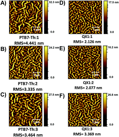 | ||
| Fig. 5 AFM topology (5 × 5 μm) images of BHJ active layers. (A) PTB7-Th:1, (B) PTB7-Th:2, (C) PTB7-Th:3, (D) QX1:1, (E) QX1:2, and (F) QX1:3. | ||
In conclusion, we have reported on the ‘side-chain’ engineering of dimeric PDI non-fullerene acceptors. For the first time, we have introduced benzyl and fluorinated benzyl side chains into the PDI scaffold. The N-annulation at the bay position of the PDI chromophore allows for facile integration of the new side chains. The addition of two(4-fluorobenzyl) and ten(pentafluorobenzyl) F-atoms onto the PDI dimer servers to slightly stabilize the frontier molecular orbital energy levels providing a method to fine tune the energetics of these PDI materials. Organic solar cells fabricated with each new PDI materials and two different donor polymers had PCEs reaching as high as 5.8%. The PDI material with benzyl side chains gave the best performance owing to the highest open circuit voltage. This work opens the door for the exploration of a myriad of side chains at the pyrrolic N-positions of these dimeric PDI materials to improve solar cell performance.
Conflicts of interest
There are no conflicts to declare.Acknowledgements
GCW acknowledges NSERC DG (435715-2013), CFI JELF (34102), CRC, and the UofC. MN and TAW are grateful for UofC Eyes High doctoral scholarships. This research was undertaken thanks in part to funding from the Canada First Research Excellence Fund (CFREF). Polymer synthesis has been financially supported by the Natural Science Foundation of Hunan Province (21875286).References
- J. Zhang, H. S. Tan, X. Guo, A. Facchetti and H. Yan, Nat. Energy, 2018, 3, 720–731 CrossRef CAS.
- A. Wadsworth, M. Moser, A. Marks, M. S. Little, N. Gasparini, C. J. Brabec, D. Baran and I. McCulloch, Chem. Soc. Rev., 2018 10.1039/C7CS00892A.
- Y. Duan, X. Xu, Y. Li and Q. Peng, Chin. Chem. Lett., 2017, 28, 2105–2115 CrossRef CAS.
- Z. Liu, Y. Wu, Q. Zhang and X. Gao, J. Mater. Chem. A, 2016, 4, 17604–17622 RSC.
- E. Kozma and M. Catellani, Dyes Pigm., 2013, 98, 160–179 CrossRef CAS.
- C. Li and H. Wonneberger, Adv. Mater., 2012, 24, 613–636 CrossRef CAS PubMed.
- H. Wang, L. Chen and Y. Xiao, J. Mater. Chem. A, 2017, 5, 22288–22296 RSC.
- D. Meng, D. Sun, C. Zhong, T. Liu, B. Fan, L. Huo, Y. Li, W. Jiang, H. Choi, T. Kim, J. Y. Kim, Y. Sun, Z. Wang and A. J. Heeger, J. Am. Chem. Soc., 2016, 138, 375–380 CrossRef CAS PubMed.
- J. Liu, S. Chen, D. Qian, B. Gautam, G. Yang, J. Zhao, J. Bergqvist, F. Zhang, W. Ma, H. Ade, O. Inganäs, K. Gundogdu, F. Gao and H. Yan, Nat. Energy, 2016, 1, 16089 CrossRef CAS.
- D. Sun, D. Meng, Y. Cai, B. Fan, Y. Li, W. Jiang, L. Huo, Y. Sun and Z. Wang, J. Am. Chem. Soc., 2015, 137, 11156–11162 CrossRef CAS PubMed.
- J. Zhang, Y. Li, J. Huang, H. Hu, G. Zhang, T. Ma, P. C. Y. Chow, H. Ade, D. Pan and H. Yan, J. Am. Chem. Soc., 2017, 139, 16092–16095 CrossRef CAS PubMed.
- Z. Luo, T. Liu, W. Cheng, K. Wu, D. Xie, L. Huo, Y. Sun and C. Yang, J. Mater. Chem. C, 2018, 6, 1136–1142 RSC.
- Y. Yin, J. Yang, F. Guo, E. Zhou, L. Zhao and Y. Zhang, ACS Appl. Mater. Interfaces, 2018, 10, 15962–15970 CrossRef CAS PubMed.
- Y. Guo, Y. Li, O. Awartani, J. Zhao, H. Han, H. Ade, D. Zhao and H. Yan, Adv. Mater., 2016, 28, 8483–8489 CrossRef CAS PubMed.
- G. Zhang, J. Zhao, P. C. Y. Chow, K. Jiang, J. Zhang, Z. Zhu, J. Zhang, F. Huang and H. Yan, Chem. Rev., 2018, 118, 3447–3507 CrossRef CAS PubMed.
- H. Hu, Y. Li, J. Zhang, Z. Peng, L. Ma, J. Xin, J. Huang, T. Ma, K. Jiang, G. Zhang, W. Ma, H. Ade and H. Yan, Adv. Energy Mater., 2018, 1800234 CrossRef.
- K. Lin, S. Wang, Z. Wang, Q. Yin, X. Liu, J. Jia, X. E. Jia, P. Luo, X. Jiang, C. Duan, F. Huang and Y. Cao, Front. Chem., 2018, 6, 328 CrossRef PubMed.
- S. H. Eom, H. S. Kim, H. J. Do, U.-H. Lee, F. T. A. Wibowo, D.-H. Hwang, S. C. Yoon and I. H. Jung, Dyes Pigm., 2018, 156, 318–325 CrossRef CAS.
- T. Welsh, A. Laventure, G. Welch, T. A. Welsh, A. Laventure and G. C. Welch, Molecules, 2018, 23, 931 CrossRef PubMed.
- T. A. Welsh, A. Laventure, T. Baumgartner and G. C. Welch, J. Mater. Chem. C, 2018, 6, 2148–2154 RSC.
- S. M. McAfee, S. V. Dayneko, A. D. Hendsbee, P. Josse, P. Blanchard, C. Cabanetos and G. C. Welch, J. Mater. Chem. A, 2017, 5, 11623–11633 RSC.
- A. D. Hendsbee, S. V. Dayneko, J. A. Pells, J. R. Cann and G. C. Welch, Sustainable Energy Fuels, 2017, 1, 1137–1147 RSC.
- A. D. Hendsbee, J.-P. Sun, W. K. Law, H. Yan, I. G. Hill, D. M. Spasyuk and G. C. Welch, Chem. Mater., 2016, 28, 7098–7109 CrossRef CAS.
- J. Cann, S. Dayneko, J.-P. Sun, A. D. Hendsbee, I. G. Hill and G. C. Welch, J. Mater. Chem. C, 2017, 5, 2074–2083 RSC.
- F. You, X. Zhou, H. Huang, Y. Liu, S. Liu, J. Shao, B. Zhao, T. Qin and W. Huang, New J. Chem., 2018, 42, 15079–15087 RSC.
- J. Mei and Z. Bao, Chem. Mater., 2014, 26, 604–615 CrossRef CAS.
- Y. Lin, J. Wang, S. Dai, Y. Li, D. Zhu and X. Zhan, Adv. Energy Mater., 2014, 4, 1400420 CrossRef.
- X. Zhang, Z. Lu, L. Ye, C. Zhan, J. Hou, S. Zhang, B. Jiang, Y. Zhao, J. Huang, S. Zhang, Y. Liu, Q. Shi, Y. Liu and J. Yao, Adv. Mater., 2013, 25, 5791–5797 CrossRef CAS PubMed.
- M. Vespa, J. R. Cann, S. V. Dayneko, O. A. Melville, A. D. Hendsbee, Y. Zou, B. H. Lessard and G. C. Welch, Eur. J. Org. Chem., 2018, 4592–4599 CrossRef CAS.
- H. Langhals and S. Kirner, Eur. J. Org. Chem., 2000, 365–380 CrossRef CAS.
- S. V. Dayneko, A. D. Hendsbee and G. C. Welch, Chem. Commun., 2017, 53, 1164–1167 RSC.
- S. M. McAfee, A.-J. Payne, A. D. Hendsbee, S. Xu, Y. Zou and G. C. Welch, Sol. RRL, 2018, 1800143 CrossRef.
- S. V. Dayneko, A. D. Hendsbee and G. C. Welch, Small Methods, 2018, 2, 1800081 CrossRef.
- Y. Sun, J. H. Seo, C. J. Takacs, J. Seifter and A. J. Heeger, Adv. Mater., 2011, 23, 1679–1683 CrossRef CAS PubMed.
- S. Zhang, L. Ye, W. Zhao, D. Liu, H. Yao and J. Hou, Macromolecules, 2014, 47, 4653–4659 CrossRef CAS.
- S. Xu, X. Wang, L. Feng, Z. He, H. Peng, V. Cimrová, J. Yuan, Z.-G. Zhang, Y. Li and Y. Zou, J. Mater. Chem. A, 2018, 6, 3074–3083 RSC.
- A.-J. Payne, J. Song, Y. Sun and G. C. Welch, Chem. Commun., 2018, 54, 11443–11446 RSC.
Footnotes |
| † During the course of the submission process, ITIC-Cl4 was reported – see ref. 25. |
| ‡ Electronic supplementary information (ESI) available: Experimental details, film characterization and device optimization. See DOI: 10.1039/c8qm00487k |
| This journal is © the Partner Organisations 2018 |

