 Open Access Article
Creative Commons Attribution 3.0 Unported Licence
A preparation method for the highly permeable ceramic microfiltration membrane – precursor film firing method
Xiaoqin Yin ,
Kang Guan,
Peng Gao,
Cheng Peng and
Jianqing Wu*
School of Materials Science and Engineering, South China University of Technology, Guangzhou 510640, China. E-mail: imjqwu@scut.edu.cn; Fax: +86 2087110273; Tel: +86 2087111669
First published on 12th January 2018
Abstract
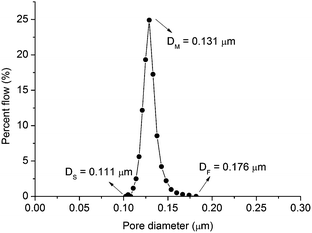
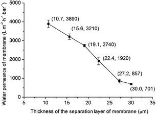
A method called the precursor film firing method is proposed to improve the permeance of ceramic microfiltration membranes by avoiding intermediate layer and dip-coating process, and efficiently control the thickness of the separation layer. In this method a precursor film is prepared independently of the support by a film coating machine. This precursor film consists of two layers: Al2O3/PVA layer made of Al2O3 powder and polyvinyl alcohol (PVA), and polyvinyl butyral (PVB) layer. The precursor film is pasted on the support and fired to obtain membranes. Because the intermediate layer and dip-coating process are avoided in this method, the fabricated membranes show high permeance. For the fabricated membrane with average pore size = 0.18 μm and separation layer thickness = 10.7 μm, the permeance is 3890 L m−2 h−1 bar−1. Also the separation layer thickness can be controlled efficiently. And the precursor film can be used on fabricate curved membranes such as cylindrical membranes.
1. Introduction
In comparison with other membranes, such as polymeric membranes, ceramic membranes show higher cost because of their high sintering temperatures and raw materials. However ceramic membranes normally show considerable mechanical strength, thermal stability and chemical compatibility.1,2 Due to these properties, they are promising in some filtration processes under harsh conditions, such as high pressure and high temperatures.Ceramic microfiltration membranes normally consist of three layers: support layer, intermediate layer and separation layer.3,4 The support layer provides mechanical strength, and the separation layer gives selectivity efficiency.4 The intermediate layer that bridges the support layer and the separation layer plays several roles:3 usually the precursor system of the separation layer such as ceramic slurry5–11 and sol12–15 are coated on supports by dip-coating technique. In the absence of the intermediate layer, the small particles in the precursor system for the separation layer will probably penetrate to the large pores of the support and decrease the permeance of the membrane. Moreover, coating a separation layer directly on a support with large pores normally may make the separation layer peel off easily.3 However, the intermediate layer will increase the total thickness of membrane system, which will reduce the permeance of membrane. Moreover, the fabrication of the intermediate layer will increase the total fabrication costs of membrane system. Hence, the ideal ceramic microfiltration membrane should consist of a support with large pores and a very thin and defect-free separation layer with controllable pore sizes.3
The permeance of membrane is sensitive to the thickness of the separation layer. The separation layer of commercial microfiltration membranes is generally in the range of 10–20 μm.3 Controlling the thickness of the separation layer is an important issue in the membrane fabrication process. In traditional dip-coating process, the liquid precursor is absorbed towards the substrate under the driving force of capillary suction pressure of the support or the external applied pressure.5 The coating thickness of the separation layer is affected by many parameters, including viscosity, density and surface tension of the precursor system; porosity, surface roughness and radius of the support; the contact time; and the withdrawal speed, etc.5 Hence, it is complex to control the thickness of the separation layer by adjusting so many parameters in traditional dip-coating technique.
Recently, Qin et al.16,17 attempted to fabricate membranes without intermediate layer based on one-step coating method and sacrificial-interlayer method. The obtained membranes show relatively high permeance in comparison with the membranes fabricated using traditional dip-coating process. However, because the dip-coating technique was also used in these two methods,16,17 the small particles in separation layer might penetrate to the big pores of support. There is still some room to improve these two methods. Moreover it is inconvenient to control the separation layer thickness using these two methods.
This study aims to propose a novel ceramic microfiltration membrane preparation method to improve the permeance of membrane by avoiding intermediate layer and dip-coating process, and efficiently control the separation layer thickness. In this method a precursor film is prepared independently of the supports by a film coating machine. This precursor film consists of two layers: Al2O3/PVA layer made of Al2O3 powder and polyvinyl alcohol (PVA), and polyvinyl butyral (PVB) layer. The precursor film is pasted on the support and fired to obtain membrane with high permeance. Because of the important role of precursor film in this method, this novel method is called precursor film firing method. It is noted that the pore size of microfiltration membrane is in a relatively wide range: 0.05–10 μm.4 To illustrate the mechanism of precursor film firing method, this study will concentrate on the membranes with pore size around 0.1–0.5 μm. However the applicability of the proposed precursor film firing method is not limited in this pore size range.
2. Experimental
2.1 Materials
2.2 Fabrication of supports
Qin et al.18 lowered the sintering temperature for fabricating high-purity porous alumina support by using boehmite. Similar to Qin et al.,18 the present study also used boehmite as a sintering additive to fabricate the supports. There are three main steps.2.3 Fabrication of microfiltration membranes using precursor film firing method
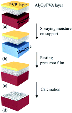 | ||
| Fig. 2 Schematic representation of fabricating ceramic microfiltration membranes using the precursor film firing method. | ||
Then, the precursor film was pasted on the support (Fig. 2b and c). When the film contacted the wet surface of the support the PVA in the Al2O3/PVA layer would partially become wetting, which provided an adhesive force for pasting the precursor film on the support. After drying at room temperature for 24 hours the precursor film with the support was calcined in air with the schedule that from room temperature to 600 °C with heating rate = 2 °C min−1 and soaked for 1 hour, subsequently heated at 5 °C min−1 to 1280 °C and soaked for 1 hour. During the calcination process PVA, PVB and other organic components in the precursor film were oxidized and volatilized. The remaining Al2O3 was sintered and the separation layer was formed (Fig. 2d).
2.4 Characterizations
The surface tension of the Al2O3/PVA slurry was measured using a contact angle measuring instrument (FM40Mk2 Easy Drop, KRÜSS GmbH, Germany) at 25 °C. The morphology of the Al2O3/PVA film was observed using a stereo microscope (L330-M1000, AOSVI, China). The thickness of the membrane and the morphology of the membrane and the support were determined with a scanning electron microscope (SEM) (ZEISS EVO 18, Germany). The pore size distribution and the porosity of the support were tested applying a mercury porosimetry (MIP) (Micrometrics AutoPore 9510, USA). The contact angle of mercury for MIP was set as 130°.Water treatment like drinking water product, municipal wastewater treatment, and food and beverage industries is an important application of microfiltration membranes.1 The present study concentrates on measuring the water permeance of membranes. The water permeance of membrane and support was measured using a fully automated fluid and gas handling systems (OSMO Inspector 2.0, Poseidon, Convergence, Netherlands) at 25 °C. As the pressure of the deionized water was gradually increased, the corresponding flow through the membrane was recorded. The water permeance was calculated based on the relationship between the transmembrane pressure and the flow. To avoid non-stationary transient effects, the membrane and the support were saturated with deionized water before the pressure was applied. The pore size distribution, largest pore size, and average pore size of membranes were tested and calculated according to ASTM: F316-03.20 The flexural strength of support is determined by three-point bending test according to ASTM: C1161-13.21 In three-point bending test, the support is cut into rectangle-shaped bar with size of 26 (length) × 4 (width) × 3 (thickness) mm3. The span of three-point bending test is fixed at 20 mm.
3. Results and discussions
3.1 Performance of the support
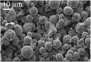
Table 1 lists the flexural strength of supports in this work and literature. The strength of ceramic supports are normally related to the porosity and the pore size. The support in this work shows higher strength than that in Qin et al.18 This is because the support in this work has smaller porosity than that in Qin et al.18 The support in this work shows lower strength than that in Dong et al.22 This is probably because the support in this work has larger average pore size than that in Dong et al.22 Fig. 3 shows the morphology of the support surface viewed using SEM. It can be seen that the Al2O3 grains are spherical and with the size of around 10 μm.Fig. 4 shows the pore size distribution and the porosity of the support measured using MIP. As shown in Fig. 4a, the pore diameter ranges from 0.82 μm to 9 μm, and the mean diameter is approximate 4.6 μm. The support shows a narrow pore size distribution (Fig. 4a) and the porosity of the support is 0.31 (Fig. 4b).
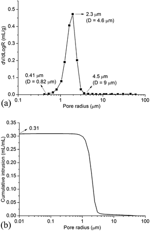 | ||
| Fig. 4 Pore size distribution and porosity of the support. (D = pore diameter) (a) pore size distribution (b) porosity. | ||
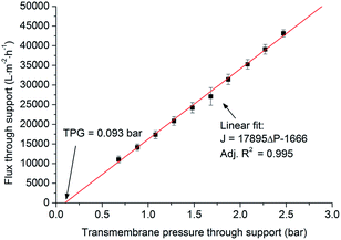
As shown in Fig. 5, the flux and the transmembrane pressure through the support exhibit a linear relationship (eqn (1)), which is similar to Darcy's law for the flow through a porous material (eqn (2)).12,23–25 The slope (17![[thin space (1/6-em)]](https://www.rsc.org/images/entities/char_2009.gif) 895 L m−2 h−1 bar−1) in eqn (1) represents the water permeance of the support. With J = 0 L m−2 h−1, eqn (1) gives ΔP = 0.093 bar. This pressure (0.093 bar) is called threshold pressure gradient (TPG). In some cases for the low-velocity flow through a porous material, the flow might not occur until the transmembrane pressure increases to the value of TPG.26,27
895 L m−2 h−1 bar−1) in eqn (1) represents the water permeance of the support. With J = 0 L m−2 h−1, eqn (1) gives ΔP = 0.093 bar. This pressure (0.093 bar) is called threshold pressure gradient (TPG). In some cases for the low-velocity flow through a porous material, the flow might not occur until the transmembrane pressure increases to the value of TPG.26,27
| J = 17895ΔP − 1666 | (1) |
 | (2) |
Table 2 lists the water permeance of the supports for microfiltration membrane in this work and literature. The water permeance of support in this work shows same order of magnitude in comparison with the water permeance of supports in literature. In general the average pore size, the porosity and the support thickness are important factors which influence the water permeance. The support in this work shows similar average pore size, porosity and support thickness to that in Dong et al.8 Accordingly, the support in this work shows similar water permeance to that in Dong et al.8
3.2 Influence of surfactant on the formulation of Al2O3/PVA film
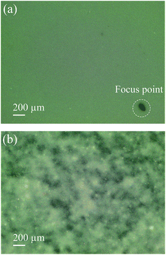
As shown in Fig. 6, if the surfactant is added in the Al2O3/PVA slurry a smooth Al2O3/PVA film can be obtained (Fig. 6a), while if the surfactant is not added in the Al2O3/PVA slurry the prepared film is uneven (Fig. 6b). This is because the addition of surfactant changes the surface tension of the Al2O3/PVA slurry. As a result the viscosity and the dispersion degree of Al2O3 powder are affected which makes the alumina powder disperse more evenly in the composite. The measured surface tensions of the Al2O3/PVA slurry made with and without fluorocarbon surfactant are 50.3 mN m−1 and 76.2 mN m−1, respectively. Due to the relatively high surface tension, the Al2O3/PVA slurry without surfactant was uneven and the Al2O3/PVA film could not be formed smoothly. Hence, the film prepared using Al2O3/PVA slurry with a relatively low surface tension is preferred.3.3 Function of the PVB layer
The precursor film consists of Al2O3/PVA layer and PVB layer. The Al2O3/PVA layer is calcined as the separation layer of membrane, while the PVB layer is used to inhibit the possible crinkles in the precursor film when the precursor film is pasted on the support. As mentioned in Section 2.3, during the process of pasting the precursor film on the support, the Al2O3/PVA layer of the precursor film will absorb the moisture on the support surface. The PVA in the Al2O3/PVA layer will partially become wetting, which provides an adhesive force for pasting the precursor film on the support. However during this process the PVA will also become swelling. As a result, crinkles might form in the precursor film. After calcination, the crinkles will be more severe. Because the PVB layer has good toughness and ductility, and is insoluble in water, it can provide a horizontal restraining force to inhibit the formation of crinkles. Fig. 7 shows that the membrane fabricated with PVB layer exhibits no significant defects (Fig. 7a), and the membrane fabricated without PVB layer has obvious crinkles (Fig. 7b).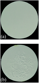 | ||
| Fig. 7 Photos of the membranes fabricated with and without PVB layer (thickness of the Al2O3/PVA layer of the precursor film is about 25 μm) (a) with PVB layer (b) without PVB layer. | ||
3.4 Performance of the membrane
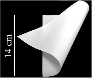 | ||
| Fig. 8 Photo of the precursor film (thickness of the Al2O3/PVA layer of the precursor film is about 25 μm). | ||
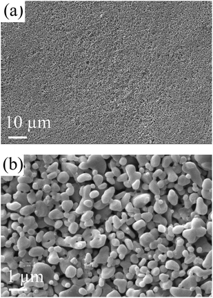
Fig. 9 shows the morphology of the membrane surface after calcination. The membrane is smooth and no significant defects can be observed.
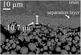 | ||
| Fig. 11 Cross section of membrane (thickness of the Al2O3/PVA layer of the precursor film is about 15 μm). | ||
Fig. 12 shows the relationship between the thickness of the separation layer and the thickness of the Al2O3/PVA layer of the precursor film. With increasing the Al2O3/PVA layer thickness from 20 μm to 40 μm, the separation layer thickness increases from 10.7 μm to 30 μm. The separation layer of commercial microfiltration membranes is in normally in the range of 10–20 μm.5 In other words, the thickness of the separation layer fabricated with the precursor film firing method meets the commercial requirement. In addition, it is found that the thickness of the separation layer (Ls, μm) linearly increases with the thickness of the Al2O3/PVA layer of the precursor film (Lp, μm) (eqn (3)). The gradient in eqn (3) represents the volume deformation of Al2O3/PVA layer during the drying at room temperature and calcination at 1280 °C.
| Ls = 0.76Lp | (3) |
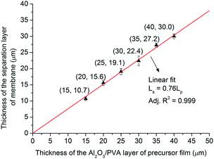 | ||
| Fig. 12 Thickness of the separation layer of membrane versus thickness of the Al2O3/PVA layer of precursor film. | ||
This linear relationship illustrates that it will be convenient to control the thickness of the separation layer with the precursor film firing method proposed in this study. As mentioned earlier, the thickness of the separation layer prepared by the traditional dip-coating method is affected by a variety of parameters, including viscosity, density and surface tension of the suspension; porosity, surface roughness and radius of the support; the contact time; and the withdrawal speed, etc.5 Hence it will be complex and difficult to control the thickness by adjusting so many parameters.
From the viewpoint of controlling the thickness of the separation layer, the precursor film firing method proposed in this study is more attractive than the traditional dip-coating technique.
| PM = J/ΔP | (4) |
Fig. 13 shows the calculated water permeance of the membrane with different separation layer thickness (ΔP = 1 bar). It can be seen that with increasing the separation layer thickness from 10.7 μm to 30.0 μm, the water permeance of the membrane decreases from 3890 L m−2 h−1 bar−1 to 701 L m−2 h−1 bar−1. This trend is also similar to the Darcy's law for the flow through a porous material (eqn (2)): the water permeance of the membrane (J/ΔP) is reciprocal to the membrane thickness (L).
Table 3 lists the permeance of membranes for microfiltration in this work and literature. The average pore sizes of these membranes are at the same order of magnitude (0.1–0.5 μm). The membrane in this work shows relatively high water permeance in comparison with other reports. For example, for the membrane with average pore size = 0.18 μm and separation layer thickness = 10.7 μm, the water permeance arrives at 3890 L m−2 h−1 bar−1. While Qin et al.16 reported that for a membrane with average pore size = 0.24 μm and separation layer thickness = 10 μm, the water permeance was 1410 L m−2 h−1 bar−1. In Dong et al.,8 the membrane consisted of three layers: support layer, intermediate layer and separation layer. The average pore size of the intermediate layer was 0.85 μm which was close to the average pore size of the separation layer (0.54 μm). This intermediate layer reduced the water permeance of the membrane system. For the membrane systems in Wang et al.10 and Qin et al.,16 intermediate layer was avoided. However because dip-coating process was used in Wang et al.10 and Qin et al.,16 the water permeance might be reduced. For example, in Wang et al.10 the size of the titania powder for fabricating separation layer was 0.37 μm, and the average pore size of the support layer was 2.1 μm. The small titania powder would probably penetrate to the big pores of the support layer during the dip-coating process. In the proposed precursor film firing method, the membrane system was obtained without intermediate layer. What's more, because the dip-coating process was avoided the small grains in the separation layer didn't access to the big pores of the support. Because of above two reasons, the obtained membrane system shows relatively high water permeance.
Table 4 lists the properties of support and separation layer. It is noted the porosity of the serration layer was not measured in this study.
| Properties | Support | Separation layer |
|---|---|---|
| Average pore size (μm) | 4.6 | 0.18 |
| Porosity | 0.31 | — |
| Permeance (L m−2 h−1 bar−1) | 17.9 × 10³ | 3.89 × 10³ |
4. Conclusions
This study proposes a novel method to fabricate ceramic microfiltration membranes. A precursor film is prepared independently of the supports by a film coating machine. This precursor film consists of two layers: Al2O3/PVA layer and PVB layer. The precursor film is pasted on the support and fired to obtain the microfiltration membrane. Based on the experimental results, the following conclusion can be drawn:The precursor film (Al2O3/PVA and PVB composite film) is flexible, which provides a potential for applying the precursor film firing method in fabricating curved membranes e.g. cylindrical membranes in addition to flat membranes.
The separation layer thickness (Ls, μm) and the thickness of the Al2O3/PVA layer (Lp, μm) follow the linear relationship: Ls = 0.76Lp. This shows that it is convenient to control the thickness of the separation layer by using the precursor film firing method. With increasing the Al2O3/PVA layer thickness from 20 μm to 40 μm, the separation layer thickness increases from 10.7 μm to 30 μm. The separation layer of commercial microfiltration membranes is in normally in the range of 10–20 μm.5 In other words, the thickness of the separation layer fabricated with the precursor film firing method meets the commercial requirement.
Because intermediate layer and dip-coating process are avoided in the precursor film firing method, the fabricated membrane shows high permeance. For the fabricated membrane with average pore size = 0.18 μm and separation layer thickness = 10.7 μm, the water permeance reaches 3890 L m−2 h−1 bar−1.
In view of the above advantages, the proposed precursor film firing method is attractive for fabricating ceramic microfiltration membranes.
Conflicts of interest
There are no conflicts to declare.Acknowledgements
This work is financially supported by the National Key Research and Development Program of China (Grant No. 2017YFB0703202) and the National Natural Science Foundation of China (Grant No. 51472092). The first author would like to thank Mr Yougen Yu, Mr Yang Liu for their help in measuring the properties of supports and membranes.References
- M. Lee, Z. Wu and K. Li, 2-Advances in ceramic membranes for water treatment, in Woodhead Publishing Series in Energy, ed. A. Basile, A. Cassano and N. K. Rastogi, Woodhead Publishing, Oxford, 2015, pp. 43–82 Search PubMed.
- E. P. Garmash, Y. N. Kryuchkov and V. N. Pavlikov, Ceramic membranes for ultra-and microfiltration (review), Glass Ceram., 1995, 52, 150–152 CrossRef.
- A. J. Burggraaf, Important characteristics of inorganic membranes, in Fundamentals of Inorganic Membrane Science and Technology, ed. A. J. Burggraaf and L. Cot, Elsevier, 1st edn, 1996, pp. 21–34 Search PubMed.
- S. Luque, D. Gómez and J. R. Álvarez, Industrial Applications of Porous Ceramic Membranes (Pressure-Driven Processes), Membr. Sci. Technol., 2008, 13, 177–216 CAS.
- B. C. Bonekamp, Preparation of asymmetric ceramic membrane supports by dip-coating, in Fundamentals of Inorganic Membrane Science and Technology, ed. A. J. Burggraaf and L. Cot, Elsevier, 1st edn, 1996, pp. 141–221 Search PubMed.
- K. Lindqvist and E. Lidén, Preparation of alumina membranes by tape casting and dip coating, J. Eur. Ceram. Soc., 1997, 17, 359–366 CrossRef CAS.
- E. Levänen and T. Mäntylä, Effect of sintering temperature on functional properties of alumina membranes, J. Eur. Ceram. Soc., 2002, 22, 613–623 CrossRef.
- Y. Dong, S. Chen, X. Zhang, J. Yang, X. Liu and G. Meng, Fabrication and characterization of low cost tubular mineral-based ceramic membranes for micro-filtration from natural zeolite, J. Membr. Sci., 2006, 281, 592–599 CrossRef CAS.
- C. Falamaki, M. Naimi and A. Aghaie, Dip-coating technique for the manufacture of alumina microfilters using PVA and Na-CMC as binders: a comparative study, J. Eur. Ceram. Soc., 2006, 26, 949–956 CrossRef CAS.
- Y. H. Wang, X. Q. Liu and G. Y. Meng, Preparation and properties of supported 100% titania ceramic membranes, Mater. Res. Bull., 2008, 43, 1480–1491 CrossRef CAS.
- A. Majhi, P. Monash and G. Pugazhenthi, Fabrication and characterization of γ-Al2O3–clay composite ultrafiltration membrane for the separation of electrolytes from its aqueous solution, J. Membr. Sci., 2009, 340, 181–191 CrossRef CAS.
- A. Leenaars and A. Burggraaf, The preparation and characterization of alumina membranes with ultrafine pores. 2. The formation of supported membranes, J. Colloid Interface Sci., 1985, 105, 27–40 CrossRef CAS.
- B. Topuz and M. Çiftçioğlu, Preparation of particulate/polymeric sol–gel derived microporous silica membranes and determination of their gas permeation properties, J. Membr. Sci., 2010, 350, 42–52 CrossRef CAS.
- H. Karimnezhad, L. Rajabi, E. Salehi, A. A. Derakhshan and S. Azimi, Novel nanocomposite Kevlar fabric membranes: Fabrication characterization, and performance in oil/water separation, Appl. Surf. Sci., 2014, 293, 275–286 CrossRef CAS.
- X. L. Pan, N. Stroh, H. Brunner, G. X. Xiong and S. S. Sheng, Deposition of sol–gel derived membranes on α- Al2O3 hollow fibers by a vacuum-assisted dip-coating process, J. Membr. Sci., 2003, 226, 111–118 CrossRef CAS.
- W. Qin, C. Peng and J. Wu, A sacrificial-interlayer technique for single-step coating preparation of highly permeable alumina membrane, Ceram. Int., 2017, 43, 901–904 CrossRef CAS.
- W. Qin, K. Guan, B. Lei, Y. Liu, C. Peng and J. Wu, One-step coating and characterization of α-Al2O3 microfiltration membrane, J. Membr. Sci., 2015, 490, 160–168 CrossRef CAS.
- W. Qin, C. Peng, M. Lv and J. Wu, Preparation and properties of high-purity porous alumina support at low sintering temperature, Ceram. Int., 2014, 40, 13741–13746 CrossRef CAS.
- F. Buss, C. C. Roberts, K. S. Crawford, K. Peters and L. F. Francis, Effect of soluble polymer binder on particle distribution in a drying particulate coating, J. Colloid Interface Sci., 2011, 359, 112–120 CrossRef CAS PubMed.
- ASTM F316-03, Standard Test Methods for Pore Size Characteristics of Membrane Filters by Bubble Point and Mean Flow Pore Test1, 2011 Search PubMed.
- ASTM C1161-13, Standard Test Methods for Flexural Strength of Advanced Ceramics at Ambient Temperature, 2013 Search PubMed.
- Y. Dong, B. Lin, J. E. Zhou, X. Zhang, Y. Ling, X. Liu, G. Meng and S. Hampshire, Corrosion resistance characterization of porous alumina membrane supports, Mater. Charact., 2011, 62, 409–418 CrossRef CAS.
- I. H. Huisman, Membrane separations | Microfiltration, in Encyclopedia of Separation Science, ed. I. D. Wilson, Academic Press, Oxford, 2000, pp. 1764–1777 Search PubMed.
- X. Ding, Y. Fan and N. Xu, A new route for the fabrication of TiO2 ultrafiltration membranes with suspension derived from a wet chemical synthesis, J. J. Membr. Sci., 2006, 270, 179–186 CrossRef CAS.
- M. Qiu, Y. Fan and N. Xu, Preparation of supported zirconia ultrafiltration membranes with the aid of polymeric additives, J. Membr. Sci., 2010, 348, 252–259 CrossRef CAS.
- Y. Huang, Z. Yang, Y. He and X. Wang, An overview on nonlinear porous flow in low permeability porous Media, Theor. Appl. Mech. Lett., 2013, 3, 022001 CrossRef.
- X. Wang and J. J. Sheng, Discussion of liquid threshold pressure gradient, Petroleum, 2017, 3, 232–236 CrossRef.
| This journal is © The Royal Society of Chemistry 2018 |


