 Open Access Article
Creative Commons Attribution 3.0 Unported Licence
A proton conductor electrolyte based on molten CsH5(PO4)2 for intermediate-temperature fuel cells
Xiaojing Chen abc,
Yichong Zhanga,
Paulo Ribeiorinhad,
Haibin Li
 *bc,
Xiangyang Konga and
Marta Boaventura*d
aSchool of Materials Science and Engineering, Shanghai Jiao Tong University, 800 Dong Chuan Road, Shanghai 200240, China
bState Key Laboratory of Ocean Engineering, Shanghai Jiao Tong University, 800 Dongchuan Road, Shanghai 200240, China. E-mail: haibinli@sjtu.edu.cn
cCollaborative Innovation Center for Advanced Ship and Deep-Sea Exploration, Shanghai Jiao Tong University, 800 Dongchuan Road, Shanghai 200240, China
dLEPABE, Faculdade de Engenharia, Universidade do Porto, Rua Dr. Roberto Frias, 4200-465 Porto, Portugal. E-mail: marta.boaventura@fe.up.pt
First published on 30th January 2018
Abstract
Molten carbonate fuel cells have been commercialized as a mature technology. Due to the liquid electrolyte in molten carbonate fuel cells, gas seal and low contact resistance are easier to achieve than in other fuel cells. Herein, we report an investigation of the viability of a molten oxoacid salt as a novel type of fuel cell electrolyte. In comparison with molten carbonate electrolytes for MCFCs that operate at 500–700 °C, for which a ceramic support matrix is required, the molten proton conductor electrolyte has a lower working temperature range of 150–250 °C. The present study has shown that an electrolyte membrane, in which molten CsH5(PO4)2 is held in a matrix made of PBI polymer and SiO2 powder, has excellent thermal stability, good mechanical properties, and high proton conductivity. In addition, a molten proton conductor fuel cell equipped with such an electrolyte membrane operating at 200 °C showed an open-circuit voltage of 1.08 V, and a stable output voltage during continuous measurement for 150 h at a constant output current density of 100 mA cm−2.
Introduction
Intermediate-temperature fuel cells (ITFCs), which operate at 120–700 °C, have many excellent features in comparison with low-temperature fuel cells (LTFCs) and high-temperature fuel cells (HTFCs). Compared with LTFCs, ITFCs offer higher tolerance of catalysts to CO, use of lower amount of precious metals, less complicated water management, and electrode kinetics and enhanced catalysis rates.1–3 In addition, compared with HTFCs, ITFCs broaden the range of available materials and elongate material lifespans. The heart of a fuel cell is its electrolyte, which determines the operating temperature range of the device. As is well known, among the various fuel cells, the molten carbonate fuel cell (MCFC) is the only one that utilizes a molten salt electrolyte. To maintain the electrolyte in the liquid state, the cell must operate at above 550 °C (the standard working temperature is 650 °C).4 Due to the liquid electrolyte of the MCFC, gas seal and low contact resistance are easier to achieve than in other types of fuel cells.5 The electrochemical reaction in the MCFC involves the formation of carbonate (CO32−) ions at the cathode and their transport to the anode via the molten carbonate electrolyte. The molten carbonate electrolyte, typically (Li0.62K0.38)2CO3 or (Li0.52Na0.48)2CO3, is usually held in a porous ceramic matrix made of lithium aluminate (LiAlO2).6 Among the various types of H2/O2 fuel cells, the MCFC has the thickest electrolyte (0.5–1.5 mm).5 It is necessary to maintain acceptable mechanical strength, as well as to counteract dissolution of the NiO cathode in molten carbonate, which may result in the formation of Ni dendrites and hence short circuiting between the electrodes.7 The thick electrolyte also results in the MCFC showing typical I–V linear characteristics, with ohmic losses dominating. Therefore, the MCFC offers the low power densities of about 100–150 mW cm−2.8,9 On the other hand, the high operating temperature of 550–650 °C limits the choice of applicable materials, since the supporting matrices of the molten carbonate electrolyte must be ceramics, which are inherently inflexible and brittle, and thus breakable.In this work, we have investigated the viability of a molten oxoacid salt as a novel type of fuel cell electrolyte. Pentahydrogen phosphates, MH5(PO4)2 (M = K, Rb, Cs), are a family of oxoacid salts, which are typically comprised of oxyanions linked together by hydrogen bonds.10,11 It has been reported that the conductivity of MH5(PO4)2 is independent of the alkaline metal cation at above 160 °C, maintaining an extremely high value of ca. 200 mS cm−1 due to the molten state.11 The oxoacid salt employed in this study, CsH5(PO4)2, melts at around 150 °C, and its melting facilitates anhydrous proton transport.12
In comparison with the molten carbonate electrolytes for MCFCs that operate at 500–700 °C, which necessitate the use of a ceramic support matrix (such as γ-LiAlO2), the molten proton conductor electrolyte has a lower working temperature range of 150–250 °C. Therefore, we can use a flexible polymer with good mechanical properties as the support matrix for holding the molten CsH5(PO4)2, which can be cast from organic solutions in a convenient and inexpensive process. In this work, polybenzimidazole (PBI) has been utilized as a polymeric matrix due to its superior mechanical strength and chemical stability, and high thermal stability up to 550 °C.13–15 The amount of CsH5(PO4)2 proton conductor loaded in the matrices is a key parameter of the electrolyte membranes due to its effect on the proton conductivity, and as much as possible should be loaded to ensure high proton conductivity. Normally, PBI polymer is free from voids, and thus it is difficult to infiltrate a significant amount of CsH5(PO4)2 melt. An efficient technique has been reported for obtaining polymer membranes with a certain distribution of voids, in which doped ceramic particles provide a well-developed porous structure, i.e. highly connected voids are formed between the particles, and thus an increase in the amount of ceramic particles results in higher porosity.13–15 On the other hand, it has been reported that in composites composed of CsH5(PO4)2 and SiO2, the addition of SiO2 powder with large surface area leads to the formation of disordered CsH5(PO4)2 at the contact interface and consequently to an increase in proton conductivity by up to 1–2 orders of magnitude compared to that of polycrystalline CsH5(PO4)2.16,17 In the present study, a composite matrix has been fabricated by combining PBI polymer and SiO2 powder in a mechanical ball-milling process followed by casting from solution, which was then immersed in a CsH5(PO4)2 melt to obtain an electrolyte membrane loaded with CsH5(PO4)2. Results have shown that such electrolyte membranes, in which molten CsH5(PO4)2 is held in a matrix composed of PBI polymer and SiO2 powder, display excellent thermal stability, good mechanical properties and high proton conductivity. Furthermore, we demonstrate a molten proton conductor fuel cell (MPCFC) based on the new kind of electrolyte membrane. The MPCFC operating at 200 °C displayed promising electrochemical performances: an open-circuit voltage (OCV) of 1.08 V and a stable output voltage over continuous measurement for 150 h at a constant output current density of 100 mA cm−2.
Results and discussion
Appearance and morphology
Membrane samples were prepared based on the preparation procedure shown in Fig. 1, which features photographs of the materials as insets. As can be seen, the SiO2/PBI matrix had a grey, opaque appearance due to the addition of SiO2 powder, whereas the pure PBI membrane was dark-brown and transparent. After loading CsH5(PO4)2 within the SiO2/PBI matrix, the Cs(SiO2/PBI) electrolyte membrane had a light-yellow, opaque appearance. All of the membranes were fully flexible.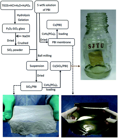 | ||
| Fig. 1 Flow chart of the preparation of all the samples involved in this work. The photographs show pure PBI, an SiO2/PBI matrix, and a Cs(SiO2/PBI) electrolyte membrane. | ||
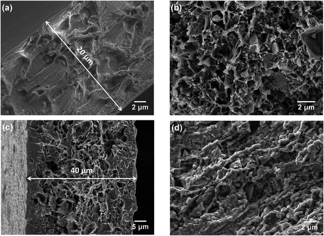
The morphologies of the membranes were observed by SEM. In Fig. 2a, it can be seen that the pure PBI membrane was free from visible pores or voids. Fig. 2b is an SEM image of the 3SiO2/7PBI matrix membrane, and shows that it consisted of a net-like PBI skeleton and SiO2 powder particles with an angular shape smaller than 1 μm embedded therein. Comparison of Fig. 2a and b clearly shows that the addition of SiO2 powder promotes the formation of a net-like PBI skeleton with a large number of voids, which will facilitate the infiltration of CsH5(PO4)2 during immersion of the SiO2/PBI matrix in a CsH5(PO4)2 melt. The cross-sectional SEM images in Fig. 2a and c reveal that the pure PBI membrane and the Cs(3SiO2/7PBI) electrolyte membrane had thicknesses of 20 and 40 μm, respectively. Fig. 2c and d show SEM images of the as-prepared Cs(3SiO2/7PBI) electrolyte membrane and after it had been subjected to a conductivity test (from 100 to 260 °C), respectively. The as-prepared Cs (3SiO2/7PBI) electrolyte membrane had a cross-sectional structure with voids in the centre and more compaction on either side, which can be rationalized in terms of penetration of the CsH5(PO4)2 melt from both faces towards the centre. Comparing Fig. 2c and d reveals the change in morphology after the conductivity test. At test temperatures up to 260 °C, CsH5(PO4)2 was in its molten liquid state and could flow into the voids in the matrix. This resulted in the formation of a compact electrolyte membrane containing highly connected CsH5(PO4)2, as shown in Fig. 2d. The connected CsH5(PO4)2 provides proton-conducting paths, which are essential for the electrolyte membranes to achieve high proton conductivity. In addition, the infilled molten CsH5(PO4)2 may serve to block gas accessibility within the electrolyte membrane. Such a compact electrolyte membrane can be expected to produce an MPCFC with a high OCV.
Thermal and mechanical properties
The thermal properties of PBI, SiO2/PBI, CsH5(PO4)2, and the electrolyte membranes consisting of SiO2/PBI matrices loaded with CsH5(PO4)2 were analysed by recording their TGA and DSC curves under a flowing air atmosphere, and the results are given in Fig. 3. As can be seen in the TGA curves in Fig. 3a, the pure PBI membrane showed a weight loss of 3.6% from 120 to 400 °C, which can be attributed to the removal of residual solvents molecules and absorbed water. Compared to the pure PBI membrane, the SiO2/PBI matrices showed lower weight losses due to the addition of inorganic SiO2 powder. Both the PBI and SiO2/PBI membranes showed outstanding thermal stability. As is evident from Fig. 3a, dehydration of CsH5(PO4)2 was initiated after melting under dry conditions,18 resulting in a weight loss of 10.5% from 150 to 400 °C. Compared to pure CsH5(PO4)2, the Cs(SiO2/PBI) electrolyte membranes showed smaller weight losses, which decreased with increasing content of inorganic SiO2 in the matrix. These electrolyte membranes are thus thermally stable and may be used in intermediate-temperature fuel cells.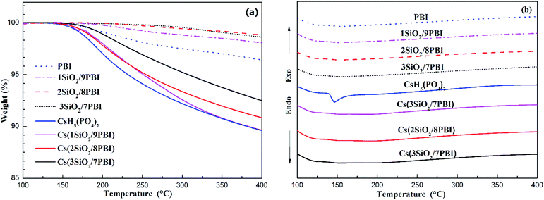 | ||
| Fig. 3 TGA (a) and DSC (b) curves of pure PBI, SiO2/PBI, CsH5(PO4)2 and the Cs(SiO2/PBI) electrolyte membranes. | ||
In the DSC curves in Fig. 3b, CsH5(PO4)2 showed a large endothermic peak at around 150 °C attributable to its melting.18,19 In contrast, the Cs(1SiO2/9PBI), Cs(2SiO2/8PBI), and Cs(3SiO2/7PBI) electrolyte membranes loaded with CsH5(PO4)2 showed no corresponding endothermic peaks. According to SEM analyses, it could be speculated that, by immersing SiO2/PBI matrices in the CsH5(PO4)2 melt, the molten CsH5(PO4)2 penetrated into the voids within the net-like PBI skeleton, resulting in a highly dispersed distribution thereof. The highly dispersed CsH5(PO4)2 and its disorder at its interface with SiO2 particles should be responsible for the disappearance of the endothermic peak corresponding to its melting point.20
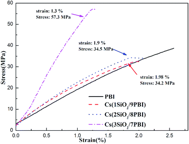
Good mechanical properties of the electrolyte membrane are essential to meet the needs of MEA fabrication in fuel cells. Fig. 4 shows stress–strain curves of the pure PBI and Cs(SiO2/PBI) electrolyte membranes measured at room temperature. It can be seen that all of the membranes had a greater than 34 MPa and an elongation of more than 1.3%, indicating good mechanical properties. It is noteworthy that, due to the high contents of the inorganic components of SiO2 powder and CsH5(PO4)2, the Cs(3SiO2/7PBI) membrane had a maximum tensile strength of 57.3 MPa, much higher than those of the other membranes.
Proton conductivities of the electrolyte membranes
Fig. 5 shows the temperature dependences of the conductivities of various electrolyte membranes consisting of pure PBI and SiO2/PBI matrices loaded with CsH5(PO4)2 under 47% H2O/N2 atmosphere. It can be seen that, for each of the electrolyte membranes, the proton conductivity increased with increasing temperature. More precisely, the temperature changes of the conductivity could be divided into four regions in the studied range between 100 and 260 °C: a gradual increase in the low-temperature range of 100–140 °C, a rapid increase in the region 140–160 °C, a slow increase in the high-temperature range up to 250 °C, and a slight decrease at temperatures over 250 °C. CsH5(PO4)2, as a proton conductor, is responsible for the proton conduction of the electrolyte membranes. The melting point of CsH5(PO4)2 is around 150 °C, as confirmed by the DSC analysis shown in Fig. 3b. In the low-temperature range of 100–140 °C, below its melting point, CsH5(PO4)2 is in the solid state and has a relatively low proton conductivity of 10−5–10−3 S cm−1.21 In the region 140–160 °C near its melting point, interfacial CsH5(PO4)2 in contact with the SiO2 powder particles and bulk CsH5(PO4)2 successively liquefied due to their different melting points, with that of the interfacial CsH5(PO4)2 being lower than that of the bulk CsH5(PO4)2.22 Molten CsH5(PO4)2 is primarily responsible for high proton conduction, resulting in a gradually increasing proton conductivity in the high-temperature range from 160 °C up to 250 °C.18,23 Above 250 °C, the decrease in conductivity of the electrolyte membranes may be ascribed to dehydration of the CsH5(PO4)2, which results in a reduction in the carrier concentration. It is noteworthy that the proton conductivities of the Cs(SiO2/PBI) electrolyte membranes increased with the increasing content of SiO2 powder, and were much higher than that of the Cs(PBI) electrolyte membrane at every temperature investigated. The SiO2 powder used had a particle size of <1 μm, as shown in Fig. 2b. From the nitrogen adsorption–desorption isotherm, the specific surface area and pore volume of SiO2 powder were evaluated as 343 m2 g−1 and 0.54 mL g−1 respectively. The pore size distribution of the SiO2 powder, determined using the BJH method, showed a peak pore size of 6 nm. The addition of SiO2 powder to the PBI polymer is seemingly helpful for obtaining electrolyte membranes with high proton conductivities in two respects. The first is the creation of voids within the matrix by the packed particles, as confirmed by SEM observation in Fig. 2b, which allows for greater infusion of the molten CsH5(PO4)2 proton conductor into the SiO2/PBI matrix. Indeed, the loading amount increased with increasing content of SiO2 powder in the electrolyte membranes, as shown in Table 1, resulting in a higher conductivity. The second factor is the formation of an extensive contact interface between the CsH5(PO4)2 and SiO2 powder, with a large specific surface area and an accessible mesoporous structure, such that it could be supposed that disordered CsH5(PO4)2 formed at the interface through interfacial interaction, resulting in an improved conductivity.22 Among all of the prepared electrolyte membranes, Cs(3SiO2/7PBI) with the highest SiO2 content, in which the most CsH5(PO4)2 was loaded, showed the highest conductivity of 64.8 mS cm−1 at 250 °C.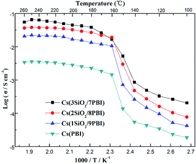 | ||
| Fig. 5 Proton conductivities of the Cs(PBI), Cs(1SiO2/9PBI), Cs(2SiO2/8PBI), and Cs(3SiO2/7PBI) electrolyte membranes under 47% H2O/N2 atmosphere. | ||
| Electrolyte membrane | Matrix | SiO2 content (wt%) | CsH5(PO4)2 loading level (wt%) |
|---|---|---|---|
| Cs(PBI) | Pure PBI | 0 | 103 |
| Cs(1SiO2/9PBI) | 1SiO2/9PBI | 10 | 241 |
| Cs(2SiO2/8PBI | 2SiO2/8PBI | 20 | 373 |
| Cs(3SiO2/7PBI) | 3SiO2/7PBI | 30 | 468 |
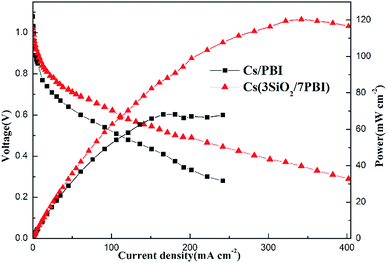
The fuel cells equipped with Cs(3SiO2/7PBI) and Cs(PBI) electrolyte membranes gave peak power densities of 120 and 68 mW cm−2, respectively. Clearly, the former is higher than the latter. The main reason is probably that, compared to the Cs(PBI) membrane, the Cs(3SiO2/7PBI) membrane with a higher loaded content of CsH5(PO4)2 has a higher proton conductivity under the fuel cell operating conditions, resulting in a lower ohmic resistance.
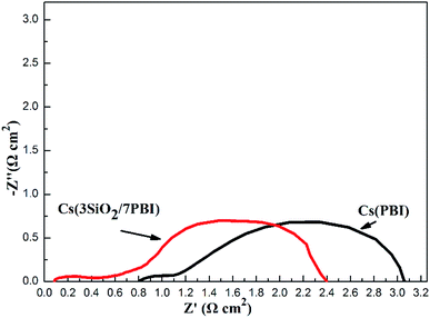
An impedance analysis of the MPAFCs was carried out with a current load of 100 mA cm−2 and impedance spectra are shown in Fig. 7. The intercept in the high-frequency domain on the real axis represents the ohmic resistance (RΩ) of the fuel cell, which is mainly ascribed to the membrane, and it is 0.084 Ω cm2 for the Cs(3SiO2/7PBI) membrane and 0.81 Ω cm2 for the Cs(PBI) membrane. Cs(3SiO2/7PBI) and Cs(PBI) electrolyte membranes have the thicknesses of 42 and 23 μm, respectively, and thus their proton conductivity could be calculated to be 50 and 2.84 mS cm−1, which are in accordance with data showed in Fig. 5. The diameter of the semicircle in the low-frequency domain is the electrode resistance (Re) from both the anode and cathode, which is 2.32 Ω cm2 for the Cs(3SiO2/7PBI) membrane and 2.30 Ω cm2 for the Cs(PBI) membrane. It is well known that creating the so-called triplephase boundaries, in which the proton conductor, catalysts, and reactants are in close contact with each other, is critical in reducing electrode resistance. In the present study, the used commercial GDEs contain Nafion resin as proton conductor. The fuel cell operating temperature of 200 °C could cause the deterioration of the proton transfer ability, resulting in the increasing electrode resistance. It is believed that the introduction of an intermediate-temperature proton conductor such as CsH5(PO4)2 instead of Nafion® resin within the GDEs should be able to achieve better triplephase boundaries, leading to the reduction of electrode resistance.
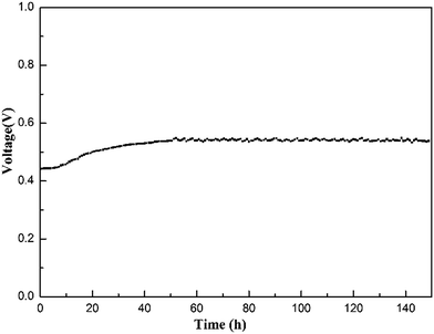
To evaluate the stability of the electrolyte membrane operating in a fuel cell, a longevity experiment was conducted at 200 °C on an MPAFC equipped with the Cs(3SiO2/7PBI) electrolyte membrane. Fig. 8 shows the stability of the output voltage with time at a constant output current density of 100 mA cm−2. After an initial increase from ca. 0.44 to 0.55 V, during the continuous measurement up to 150 h, the fuel cell showed good stability at around 0.55 V, indicating high stability of the electrolyte membrane under the operating conditions.
Conclusions
In the present study, we have succeeded in preparing proton-conducting electrolyte membranes loaded with molten CsH5(PO4)2, and have constructed a working fuel cell. Although further improvements, such as better MEA design, are definitely required, the presented results proved that molten proton conductor electrolyte membranes show advantages of non-permeability of fuel gases, sufficient proton conductivity, high thermal stability, good mechanical properties, and low fabrication cost.So far, various ITFCs including MCFC and phosphoric acid fuel cell (PAFC) have been developed, and they have varying operating temperatures, covering the intermediate-temperature range from 120 °C up to 700 °C. Table 2 summarizes the operating temperature, electrolyte, matrix and mobile ion information of the MPCFC using the molten proton conductor electrolyte in comparison with the MCFC and PAFC as conventional ITFCs. Under the high operation temperatures of 500–700 °C, molten carbonate fuel cell suffers from a high stresses due to thermal cycling. On the other hand, the advantages of using the PBI polymeric matrix to retain the electrolyte in liquid form in MPCFC and PAFC over the ceramic matrix such as the LiAlO2 in MCFC and the SiC matrix in PAFC include, easy handling, thinner electrolyte thickness, less cost and better tolerance towards pressure differences between cathode and anode.
| Type | Operating temperature | Electrolyte | Matrix | Mobile ion |
|---|---|---|---|---|
| MPCFC | 150–250 °C | Molten proton conductor (CsH5(PO4)2) | PBI (polymer) | H+ |
| MCFC | 500–700 °C | Molten carbonate ((Na, K)2CO3) | LiAlO2 (ceramic) | CO32− |
| PAFC | 120–200 °C | H3PO4 | SiC (ceramic) | H+ |
| 120–200 °C | H3PO4 | PBI (polymer) | H+ |
One of the main drawbacks of fuel cells that are hindering their widespread commercialization are hydrogen infrastructure. Methanol is such a liquid hydrogen carrier, and has the lowest reforming temperature, around 200–300 °C compared to other hydrocarbons. A way of using methanol is by means of methanol reforming, where it is used to produce hydrogen rich mixture of gases that can be utilized in fuel cells. Due to the mismatch on the operating temperature between the low-temperature methanol reformer (200–300 °C) and the PAFC (120–200 °C), the heat released by the PAFC is mostly wasted, and thus the simplest and most efficient way to achieve heat integration is having both ITFCs and methanol reformer operated at same temperature.25 The MPCFC using molten proton conductor electrolyte can operate at a temperature from 150 °C up to 250 °C, which allows matching methanol reforming (200–300 °C), making it very attractive for the possibility of its integration with methanol reformer. It could be expected that new types of MPCFCs using the molten proton conductor electrolytes capable of operating at intermediate temperatures would considerably affect the direction of current intermediate-temperature fuel cell research.
Experimental section
Materials
Si(OC2H5)4 (TEOS), NaOH, HCl, H3PO4 (85 wt% in water), LiCl, and Cs2CO3 (99.9% trace metals basis) were purchased from Shanghai Sinopharm Chemical Reagent Co., Ltd. N,N-dimethyl-acetamide (DMAc) was purchased from Shanghai Lingfeng Chemical Reagent Co. Ltd. Polybenzimidazole (PBI) was purchased from Shanghai Shengjun Polymer Technologies Co. Ltd. Silver paste (DAD-40) was purchased from the Shanghai Research Institute of Synthetic Resins. All materials were used as received without further purification.Preparation
![[thin space (1/6-em)]](https://www.rsc.org/images/entities/char_2009.gif) :
:![[thin space (1/6-em)]](https://www.rsc.org/images/entities/char_2009.gif) 4
4![[thin space (1/6-em)]](https://www.rsc.org/images/entities/char_2009.gif) :
:![[thin space (1/6-em)]](https://www.rsc.org/images/entities/char_2009.gif) 4 × 10⁻³ (TEOS
4 × 10⁻³ (TEOS![[thin space (1/6-em)]](https://www.rsc.org/images/entities/char_2009.gif) :
:![[thin space (1/6-em)]](https://www.rsc.org/images/entities/char_2009.gif) H2O
H2O![[thin space (1/6-em)]](https://www.rsc.org/images/entities/char_2009.gif) :
:![[thin space (1/6-em)]](https://www.rsc.org/images/entities/char_2009.gif) HCl) was firstly prepared and stirred for 30 min at room temperature, and then H3PO4 was added to give a molar ratio of 7
HCl) was firstly prepared and stirred for 30 min at room temperature, and then H3PO4 was added to give a molar ratio of 7![[thin space (1/6-em)]](https://www.rsc.org/images/entities/char_2009.gif) :
:![[thin space (1/6-em)]](https://www.rsc.org/images/entities/char_2009.gif) 3 (TEOS
3 (TEOS![[thin space (1/6-em)]](https://www.rsc.org/images/entities/char_2009.gif) :
:![[thin space (1/6-em)]](https://www.rsc.org/images/entities/char_2009.gif) H3PO4) and the mixture was stirred for 1 h. The obtained transparent solution was then transferred to a Teflon vessel and left to stand at room temperature until gelation occurred. Neutralization of the acidic gel was a necessary step to avoid the precipitation of PBI with a basic amino group (–NH2) when the acidic inorganic material was added to the solution. The SiO2 gel monolith containing phosphoric acid was immersed in 2 mol L−1 NaOH solution to neutralize the H3PO4 contained therein, then washed repeatedly with distilled water until the washings reached neutral pH, and subsequently dried at 120 °C for 24 h, so that a neutral SiO2 gel monolith was obtained. Finally, the SiO2 gel monolith was crushed to SiO2 powder using an agate mortar, and this powder was kept under a dry atmosphere before use.
H3PO4) and the mixture was stirred for 1 h. The obtained transparent solution was then transferred to a Teflon vessel and left to stand at room temperature until gelation occurred. Neutralization of the acidic gel was a necessary step to avoid the precipitation of PBI with a basic amino group (–NH2) when the acidic inorganic material was added to the solution. The SiO2 gel monolith containing phosphoric acid was immersed in 2 mol L−1 NaOH solution to neutralize the H3PO4 contained therein, then washed repeatedly with distilled water until the washings reached neutral pH, and subsequently dried at 120 °C for 24 h, so that a neutral SiO2 gel monolith was obtained. Finally, the SiO2 gel monolith was crushed to SiO2 powder using an agate mortar, and this powder was kept under a dry atmosphere before use.![[thin space (1/6-em)]](https://www.rsc.org/images/entities/char_2009.gif) :
:![[thin space (1/6-em)]](https://www.rsc.org/images/entities/char_2009.gif) 4 was concentrated to dryness overnight at 100 °C and then the resultant white solid was kept under a dry atmosphere prior to use.
4 was concentrated to dryness overnight at 100 °C and then the resultant white solid was kept under a dry atmosphere prior to use.![[thin space (1/6-em)]](https://www.rsc.org/images/entities/char_2009.gif) :
:![[thin space (1/6-em)]](https://www.rsc.org/images/entities/char_2009.gif) LiCl, 100
LiCl, 100![[thin space (1/6-em)]](https://www.rsc.org/images/entities/char_2009.gif) :
:![[thin space (1/6-em)]](https://www.rsc.org/images/entities/char_2009.gif) 3, w/w) were dissolved in DMAc with vigorous stirring at 120 °C for 5 h to form a 5 wt% solution. This solution was then cast onto a glass plate. A pure PBI membrane was obtained by initially drying at 70 °C for 10 h, then at 120 °C for 10 h, and finally at 120 °C under vacuum overnight. It was then peeled off from the glass plate, and washed in boiling water for 10 h to remove LiCl and residual DMAc.
3, w/w) were dissolved in DMAc with vigorous stirring at 120 °C for 5 h to form a 5 wt% solution. This solution was then cast onto a glass plate. A pure PBI membrane was obtained by initially drying at 70 °C for 10 h, then at 120 °C for 10 h, and finally at 120 °C under vacuum overnight. It was then peeled off from the glass plate, and washed in boiling water for 10 h to remove LiCl and residual DMAc.SiO2/PBI matrix membranes were prepared according to the following procedure. First, the requisite amounts of SiO2 were incorporated into 5 wt% PBI solutions. The obtained mixtures of PBI and SiO2 were milled in a planetary ball-milling apparatus (QM-3SP2, NanDa Instrument Plant) for 24 h at 580 rpm and then cast onto glass plates. The SiO2/PBI composite matrices were obtained by initially drying at 70 °C for 10 h, then at 120 °C for 10 h, and finally at 120 °C under vacuum overnight. They were then peeled off from the glass plate, and washed in boiling water for 10 h to remove LiCl and residual DMAc.
To indicate the different weight ratios of SiO2 powder and PBI polymer in the SiO2/PBI matrices, such as 1![[thin space (1/6-em)]](https://www.rsc.org/images/entities/char_2009.gif) :
:![[thin space (1/6-em)]](https://www.rsc.org/images/entities/char_2009.gif) 9, 2
9, 2![[thin space (1/6-em)]](https://www.rsc.org/images/entities/char_2009.gif) :
:![[thin space (1/6-em)]](https://www.rsc.org/images/entities/char_2009.gif) 8, and 3
8, and 3![[thin space (1/6-em)]](https://www.rsc.org/images/entities/char_2009.gif) :
:![[thin space (1/6-em)]](https://www.rsc.org/images/entities/char_2009.gif) 7, they were designated as 1SiO2/9PBI, 2SiO2/8PBI, and 3SiO2/7PBI, respectively.
7, they were designated as 1SiO2/9PBI, 2SiO2/8PBI, and 3SiO2/7PBI, respectively.
The proton conductivities of the electrolyte membranes were determined by means of an impedance/gain phase analyser (SI 1260, Solartron) over the frequency range from 10−1 to 107 Hz with a voltage amplitude of 20 mV. Measurements were carried out over the temperature range from 100 to 260 °C under a 47% H2O/N2 atmosphere generated by bubbling dry N2 through water at 80 °C. A two-electrode a.c. method described in a previous study27 was applied for these measurements. Two parallel silver stripe electrodes connected with gold wires were obtained by painting silver paste on each electrolyte membrane. To obtain a steady state, a time interval of 30 min between adjacent temperatures (testing temperature elevated by 10 °C) was selected. The electrolyte resistance was estimated from the intercept on the real axis at the high-frequency end of the impedance spectra. The proton conductivities of the electrolyte membranes were calculated according to the following equation:
| σ = a/dLR | (1) |
Single cells of the MPCFC were fabricated using the Cs(PBI) and Cs(3SiO2/7PBI) electrolyte membranes. The electrolyte membranes were sandwiched between two gas diffusion electrodes (GDEs) with Pt loadings of 0.5 mg cm−2 (S10CC, SGL Group) without a hot-pressing procedure to form a membrane-electrode assembly (MEA) with an active area of 5 cm2. These single cells were fueled with humidified hydrogen at the anode and dry oxygen at the cathode, respectively. The gas flow rates of H2 and O2 were both set at 60 cm3 min−1 at 1 bar. Humidification of H2 at the anode was achieved by feeding water at a flow rate of 0.12 ml min−1 into the gas flow. The MPCFCs were characterized by polarization curves and electrochemical impedance spectroscopy (EIS). EIS were obtained at 100 mA cm−2, between 10−1 and 105 Hz with a perturbation amplitude of 5 mV. A durability test of the MPCFC assembled with the Cs(3SiO2/7PBI) electrolyte membrane was conducted by operating under a constant output current density of 100 mA cm−2 at 200 °C.
Conflicts of interest
There are no conflicts to declare.Acknowledgements
This work was supported by the International Science & Technology Cooperation Program of the Ministry of Science & Technology (grant No. 2015DFG62250), and Project POCI-01-0145-FEDER-006939 (Laboratory for Process Engineering, Environment, Biotechnology, and Energy – LEPABE funded by FEDER funds through COMPETE2020 – Operational Program Competitiveness and Internationalization (POCI) – and by national funds through FCT – Foundation for Science and Technology). This research was partially supported by the project “Flexible glass-based proton exchange membrane and MEA for high temperature PEMFC” financed by FCT and MOST. X. K. would thank the financial support by NSFC No. 21761132004.References
- S. M. Haile, D. A. Boysen, C. R. I. Chisholm and R. B. Merle, Nature, 2001, 410, 910–913 CrossRef CAS PubMed.
- S. M. Haile, C. R. I. Chisholm, K. Sasaki, D. A. Boysen and T. Uda, Faraday Discuss., 2007, 134, 17–39 RSC.
- A. H. Jensen, Q. Li, E. Christensen and N. J. Bjerrum, J. Electrochem. Soc., 2014, 161, F72–F76 CrossRef CAS.
- Advances in Molten Salt Chemistry, ed. J. R. Selman, H. C. Maru, L. G. Marianowski, E. Ong, A. Pigeaud, V. Sampath, I. G. Mamantov, J. Braunstein and C. B. Mamantov, Plenum Press, New York, 1981, vol. 4, pp. 159–388 Search PubMed.
- P. Tomczyk, J. Power Sources, 2006, 160, 858–862 CrossRef CAS.
- T. Kojima, Y. Miyazaki, K. Nomura and K. Tanimoto, J. Electrochem. Soc., 2007, 154, F222–F230 CrossRef CAS.
- P. Tomczyk, Y. Ono, Y. Hisamitsu, M. Mohamedi and I. Uchida, Electrochem. Solid-State Lett., 1999, 2, 431–433 CrossRef CAS.
- H.-J. Choi, J.-J. Lee, S.-H. Hyun and H.-C. Lim, Int. J. Hydrogen Energy, 2011, 36, 11048–11055 CrossRef CAS.
- J. Soler, T. González, M. J. Escudero, T. Rodrigo and L. Daz, J. Power Sources, 2002, 106, 189–195 CrossRef CAS.
- E. Philippot and O. Lindqvist, Acta Chem. Scand., 1971, 25, 512 CrossRef CAS.
- H. Muroyama, K. Kudo, T. Matsui, R. Kikuchi and K. Eguchi, Solid State Ionics, 2007, 178, 1512–1516 CrossRef CAS.
- T. Matsui, T. Kukino, R. Kikuchi and K. Eguchi, Electrochim. Acta, 2006, 51, 3719–3723 CrossRef CAS.
- S. Y. Oh, T. Yoshida, G. Kawamura, H. Muto, M. Sakai and A. Matsuda, J. Mater. Chem., 2010, 20, 6359–6366 RSC.
- H. Pu, L. Liu, Z. Chang and J. Yuan, Electrochim. Acta, 2009, 54, 7536–7541 CrossRef CAS.
- M. Q. Li, Z. G. Shao and K. Scott, J. Power Sources, 2008, 183, 69–75 CrossRef CAS.
- G. V. Lavrova and V. G. Ponomareva, Solid State Ionics, 2008, 179, 1170–1173 CrossRef CAS.
- A. Epiphanova, O. Magaev and O. Vodyankina, J. Sol-Gel Sci. Technol., 2012, 61, 509–517 CrossRef CAS.
- H. Muroyama, T. Matsui, R. Kikuchi and K. Eguchi, J. Electrochem. Soc., 2008, 155, B958–B962 CrossRef CAS.
- G. V. Lavrova, E. B. Burgina, A. A. Matvienko and V. G. Ponomareva, Solid State Ionics, 2006, 177, 1117–1122 CrossRef CAS.
- V. G. Ponomareva and E. S. Shutova, Solid State Ionics, 2007, 178, 729–734 CrossRef CAS.
- G. Lavrova and V. Ponomareva, Russ. J. Electrochem., 2007, 43, 454–461 CrossRef CAS.
- G. Qing and R. Kikuchi, Solid State Ionics, 2016, 289, 133–142 CrossRef CAS.
- T. Matsui, H. Muroyama, R. Kikuchi and K. Eguchi, J. Jpn. Pet. Inst., 2010, 53, 1–11 CrossRef CAS.
- S. Srinivasan, O. A. Velev, A. Parthasarathy, D. J. Manko and A. J. Appleby, J. Power Sources, 1991, 36, 299–320 CrossRef CAS.
- P. Ribeirinha, G. Schuller, M. Boaventura and A. Mendes, Int. J. Hydrogen Energy, 2017, 42, 13902–13912 CrossRef CAS.
- H. Li, D. Jin, X. Kong, H. Tu, Q. Yu and F. Jiang, Microporous Mesoporous Mater., 2011, 138, 63–67 CrossRef CAS.
- Q. Xie, Y. Li, J. Hu, X. Chen and H. Li, J. Membr. Sci., 2015, 489, 98–105 CrossRef CAS.
| This journal is © The Royal Society of Chemistry 2018 |

