 Open Access Article
Adsorption of an Au atom and dimer on a thin θ-Al2O3/NiAl(100) film: dependence on the thickness of the θ-Al2O3 film†
Ching-Lun Hsiaa,
Jeng-Han Wang *b and
Meng-Fan Luo
 *a
*a
aDepartment of Physics, National Central University, 300 Jhongda Road, Jhongli District, Taoyuan 32001, Taiwan. E-mail: mfl28@phy.ncu.edu.tw
bDepartment of Chemistry, National Taiwan Normal University, Taipei, Taiwan. E-mail: jenghan@ntnu.edu.tw
First published on 10th January 2018
Abstract
With calculations based on density-functional theory (DFT) we investigated the adsorption of a single Au atom and a dimer on thin θ-Al2O3(001) films supported on NiAl(100). The interaction of the Au adsorbates with the surface was shown to depend on the thickness of the film. The adsorption energy for an Au atom on θ-Al2O3(001)/NiAl(100) of film thickness ≤four atomic layers was significantly enhanced—over three times that on a bulk θ-Al2O3(001) surface, and accompanied with a shortened Au-oxide bond and an uplifted Au-binding Al. The strong Au-surface interaction involved a decreased work function of θ-Al2O3(001)/NiAl(100) and consequently drove charge to transfer from the substrate to the adsorbed Au atom; the charge was transferred from NiAl, through alumina, on monolayer θ-Al2O3(001)/NiAl(100), but directly from alumina on thicker layers. For an Au dimer, both upright (end-on) and flat-lying (side-on) geometries existed. The flat-lying dimer was preferred on mono- and tri-layer alumina films, having a greater adsorption energy but a weakened Au–Au bond, whereas the upright geometry prevailed for films of other thickness, having a weaker adsorption energy and being less charged, similar to that on a bulk θ-Al2O3(001) surface. The results imply an opportunity to control the properties and morphologies of metal clusters supported on an oxide film by tuning its thickness.
Introduction
Metal nanoclusters supported on thin oxide films grown on metal single crystals have been widely studied as a realistic model system for catalysis in recent decades.1–6 Such studies exhibit some common catalytic features as observed in real-world catalysts, and allow detailed investigation of the structure–reactivity correlation.1–10 The results indicate that the catalytic properties depend on not only the size of the metal clusters8–15 but also the thickness of the oxide film.16 For instance, both experiments and theoretical simulations show that Au atoms or clusters on MgO/Ag(001) are negatively charged, through an electron transfer from the Ag substrate to the Au atoms, when the MgO film amounts to three monolayers; in contrast, Au adsorbates become neutral on a thick MgO film.17–19 Such charged Au clusters have also induced activation of CO2.20,21 Similar charge transfer was observed for Au on FeO/Pt(111).22,23 Moreover, adhesive binding of metal clusters to the thin oxide film is indicated to vary with the thickness of the film, resulting in altered cluster morphologies and, likely, catalytic properties.24,25 The features dependent on the film thickness have opened a new dimension for the design of model systems or even catalysts. The present work is devoted to exploring such effects on the adsorption of metal atoms or clusters.Assisted with calculations based on density-functional theory (DFT), we investigated the adsorption behavior of Aun adsorbates (n = 1 or 2; n denotes the number of Au atoms constituting the adsorbate) on a thin film of alumina (Al2O3) grown on NiAl(100). Oxide-supported Au clusters attract much attention as they exhibit an extraordinary catalytic activity, in contrast with their bulk state, toward various reactions encompassing oxidation of carbon monoxide, oxidation and hydrochlorination of hydrocarbons, reduction of nitrogen monoxide, the water–gas-shift reaction and methanol decomposition.7,8,26–31 These atypical catalytic properties rely critically on the Au cluster size. The understanding of the interaction between Au and its supporting oxides becomes essential, as it allows ones to adequately manipulate the cluster size, morphology and hence reactivity. Al2O3 is a popular support for catalysts; a thin Al2O3/NiAl(100) film has been studied and used as a model system.15,32–41 We have performed simulations with alumina slabs of 1–5 atomic layers atop a NiAl(100) slab of 11 or 12 atomic layers. The alumina slabs have the structure of θ-Al2O3 and a surface termination of the (001) facet to match previous experimental results.32–35,42
Our results show that the interaction of Au adsorbates with the surface depends significantly on the thickness of the alumina film. For a single Au atom, the dependence is reflected in the adsorption site, adsorption energy, Au-oxide bond length and adsorption-induced structural alteration. The adsorption energy for a film thickness ≤4 atomic layers is remarkably enhanced with respect to that of a bulk θ-Al2O3(001) surface. The strong Au-surface interaction involves a charge transfer from the substrate to the adsorbed Au, and that, resembling Au on MgO/Ag(001) and MgO/Mo(001),17–19 is associated with a decreased work function of alumina/NiAl(100). On a monolayer alumina film, the charge was transferred from NiAl to an adsorbed Au by tunneling through the alumina film. For an Au dimer, both upright and flat-lying geometries exist, but, in contrast with Au dimers on MgO/Ag(001),43 the preferred configuration depends on the film thickness. The flat-lying dimer is found on mono- and tri-layer alumina and is governed energetically by the Au-surface interaction, whereas the upright one on alumina of another thickness behaves like the dimer on a bulk θ-Al2O3(001) surface. These disparate adsorption configurations might provide clues to understand the two-dimensional (2D) structures and atypical bimodal distribution of the size of Au clusters observed on Al2O3/NiAl(100).44 These results also confirm the possibility that tuning the thickness of the thin oxide film allows one to manipulate the properties and morphologies of supported metal clusters.
Computational details
We performed DFT calculations with the Vienna Ab initio Simulation Program (VASP),45–47 with projector-augmented waves48 and the generalized-gradient approximation proposed by Perdew et al.49 The alumina/NiAl(100) surfaces were represented in a fixed supercell comprising a θ-Al2O3 slab of 1–5 atomic layers on top of a NiAl slab of 11 or 12 atomic layers with Ni or Al termination, which was separated from its periodic images by a vacuum region of thickness at least 15 Å to avoid interactions between the slabs; the bottom three NiAl layers were fixed at their optimal positions derived from NiAl bulk calculations and the other layers were free to relax. A (4 × 4) cell (11.25 × 11.66 Å2) was typically used in the present calculations, despite the θ-Al2O3(001) surface has a primitive surface unit cell (2 × 1).32–35,42 Brillouin-zone integration is sampling in the reciprocal space by a Monkhorst pack k-point grid of (3 × 3 × 1). A plane-wave energy cut-off (ENCUT) at 400 eV and an error 10−5 eV allowed in total energy (EDIFF) were applied. These parameters were justified as an even smaller energetic convergence, larger k-point grids and cut-off energies, such as 10−6, (4 × 4 × 1) and 520 eV, gave negligible differences of calculated adsorption energies (less than 10 meV). The structures of Aun adsorbates (n = 1 or 2) on the alumina/NiAl(100) were also optimized with the bottom three NiAl layers fixed at their bulk positions and the other layers allowed to relax fully. The charge transfer between the oxide and Aun upon adsorption was derived on counting the difference in the number of valence electrons (Bader charge) of the adsorbed atoms.We calculated gaseous Aun by placing a monomer or dimer in a cell of the same size as that employed for the surface calculation, which is sufficiently large to prevent interaction between Aun in neighboring unit cells. All the calculations were performed based on spin-polarized DFT, since a free Au atom exhibits spin polarization. The calculated bond length, 2.52 Å, and dissociation energy, 2.28 eV, of an Au2 dimer match well with experimental values, 2.47 Å and 2.29 eV,50 respectively, so the present computational capability is reliable.
The adsorption energy for an Aun adsorbate is defined as
 | (1) |
 is the total energy of a free gaseous Aun. To explore the clustering energetics, we also calculated the cohesive energy of an adsorbed Aun, defined as
 | (2) |
Results and discussion
In this section, we explain how we constructed the thin alumina films supported on NiAl(100) (θ-Al2O3/NiAl(100)) and demonstrate how we simulated adsorption of a single Au atom and dimer on the oxide surfaces. The simulation shows that the most stable configurations for a single Au atom and a dimer on the alumina films varied with their thickness. The origin of this thickness-dependent adsorption is discussed and associated with a structural relaxation, decreased work function, facilitated charge transfer and varied density of states (DOS).1. Determination of surface structures of a thin θ-Al2O3/NiAl(100) film
Preceding studies with LEED, EELS, RHEED, STM and modeling have indicated that the thin alumina films grown on NiAl(100) at elevated temperatures have a structure of θ-Al2O3 and a surface termination of the (001) facet.32–35,42 This orientation is preferred as θ-Al2O3(001) has an oxygen or Al lattice that matches better the square Al or Ni lattice of NiAl(100). The present alumina films were therefore simulated based on the structure of θ-Al2O3(001). The θ-Al2O3/NiAl(100) surfaces were represented in a supercell comprising a θ-Al2O3 slab (1–5 atomic layers) on top of a NiAl slab (11 or 12 atomic layers) terminated with Ni or Al. Although the ratio 2![[thin space (1/6-em)]](https://www.rsc.org/images/entities/char_2009.gif) :
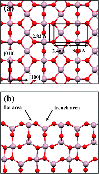
:![[thin space (1/6-em)]](https://www.rsc.org/images/entities/char_2009.gif) 3 of Al to O might not be sustained in the θ-Al2O3 slabs, we use the same notation for brevity. Both θ-Al2O3 and NiAl(100) slabs were simulated based on structural information obtained from experimental results.32,42,51,52 As the calculated lattice parameters of bulk θ-Al2O3 (a = 5.63 Å, b = 2.92 Å, c = 11.76 Å, β = 103.96°) and bulk NiAl (a0 = 2.89 Å) agree satisfactorily with experiments (a = 5.64 Å, b = 2.92 Å, c = 11.83 Å, β = 104°, a0 = 2.89 Å),32,42,51,52 we confidently used the calculated lattice parameters to construct the film slabs to simulate the surfaces. The θ-Al2O3(001) film slab has four possible surface terminations, derived by cleaving the unit cell of the oxide at various planes, and all four surface terminations (after undergoing relaxation) exhibit a (2 × 1) surface unit cell,53 consistent with diffraction measurements.32–35 Nevertheless, only one termination, shown schematically in Fig. 1(a), is energetically more stable53 and matches the atomically resolved STM images of θ-Al2O3(001)/NiAl(100).34,42 We thus constructed the θ-Al2O3 slab with this surface termination exposed to vacuum and with the other side bound to NiAl(100). The unit cell of such a surface termination has an armchair-like configuration containing flat (left part) and trench (right part) areas (Fig. 1(b)); the other side of the θ-Al2O3 slab (bound to NiA1(100)) varies with the slab thickness.
3 of Al to O might not be sustained in the θ-Al2O3 slabs, we use the same notation for brevity. Both θ-Al2O3 and NiAl(100) slabs were simulated based on structural information obtained from experimental results.32,42,51,52 As the calculated lattice parameters of bulk θ-Al2O3 (a = 5.63 Å, b = 2.92 Å, c = 11.76 Å, β = 103.96°) and bulk NiAl (a0 = 2.89 Å) agree satisfactorily with experiments (a = 5.64 Å, b = 2.92 Å, c = 11.83 Å, β = 104°, a0 = 2.89 Å),32,42,51,52 we confidently used the calculated lattice parameters to construct the film slabs to simulate the surfaces. The θ-Al2O3(001) film slab has four possible surface terminations, derived by cleaving the unit cell of the oxide at various planes, and all four surface terminations (after undergoing relaxation) exhibit a (2 × 1) surface unit cell,53 consistent with diffraction measurements.32–35 Nevertheless, only one termination, shown schematically in Fig. 1(a), is energetically more stable53 and matches the atomically resolved STM images of θ-Al2O3(001)/NiAl(100).34,42 We thus constructed the θ-Al2O3 slab with this surface termination exposed to vacuum and with the other side bound to NiAl(100). The unit cell of such a surface termination has an armchair-like configuration containing flat (left part) and trench (right part) areas (Fig. 1(b)); the other side of the θ-Al2O3 slab (bound to NiA1(100)) varies with the slab thickness.
We considered twenty θ-Al2O3/NiAl(100) models, including θ-Al2O3 slabs of 1–5 atomic layers and θ-Al2O3–NiAl(100) interfaces of Al–Al, O–Al, Al–Ni and O–Ni bondings. Only seven models (among the twenty) were energetically converged. Fig. 2(a)–(g) show the side views of θ-Al2O3(001), as a comparison, and the seven θ-Al2O3/NiAl(100) models. The symbols 1L–5L in the figures indicate models with 1–5 atomic layers in the θ-Al2O3 slabs. Models 2L and 5L have two stable bondings at the interface: O–Ni (Fig. 2(c) and (g)) and O–Al (Fig. 2(d) and (h)), denoted as 2L–O–Ni (5L–O–Ni) and 2L–O–Al (5L–O–Al), respectively. In the θ-Al2O3/NiAl(100) models, the atomic structures of either θ-Al2O3 or NiAl far from the interface resemble their counterparts in the bulk but those at or near the interface vary. Models 1L (Fig. 2(b)) and 4L (Fig. 2(f)) have similar bonding structures at the interface: Al atoms (grey) of θ-Al2O3 are bound to Ni atoms (blue) of NiAl. The interatomic distance between the Ni atoms (circled in Fig. 2(b) and (f)) bound to the same Al atoms of θ-Al2O3 at the interface decreased to 2.64 Å, relative to the bulk value 2.81 Å. The structural alteration at the interface for models 2L–O–Ni (Fig. 2(c)) and 2L–O–Al (Fig. 2(d)) differs evidently. The atoms at the interface in model 2L–O–Ni became strongly rearranged; the Ni atoms at the top layer of NiAl were driven from their initial bulk positions to bind the O atoms of θ-Al2O3. In contrast, those in model 2L–O–Al remained at positions similar to those of their counterparts in bulk θ-Al2O3 and NiAl. Model 3L (Fig. 2(e)) has O–Al bonds at the interface; their length along direction [001] is about 2.0 Å (circled in Fig. 2(e)), greater than that (or of the O–Ni bond) in other models, typically 1–2 Å along direction [001]. As the θ-Al2O3 and NiAl slabs in Model 3L are most separated, this structure might be most unstable and energetically unfavorable. The interface structures of models 5L–O–Ni (Fig. 2(g)) and 5L–O–Al (Fig. 2(h)) are similar to those of 2L–O–Ni and 2L–O–Al, respectively. The interface restructuring in model 5L–O–Ni is likewise more evident than that in model 5L–O–Al, but less severe than that in 2L–O–Ni.
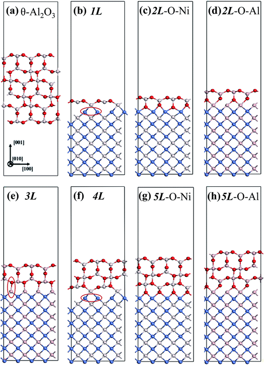 | ||
| Fig. 2 Schematic diagrams showing side views of (a) bulk θ-Al2O3(001) and (b)–(h) seven θ-Al2O3/NiAl(100) models, as indicated. Red, grey and blue spheres denote O, Al and Ni atoms, respectively. | ||
2. Adsorption of a single Au atom on a thin θ-Al2O3/NiAl(100) film
We placed a single Au atom at varied locations on θ-Al2O3/NiAl(100) to investigate the energetically preferable site and the corresponding adsorption energy . We explored the dependence of adsorption properties on the thickness of the θ-Al2O3 films and discuss the origin of the dependence.
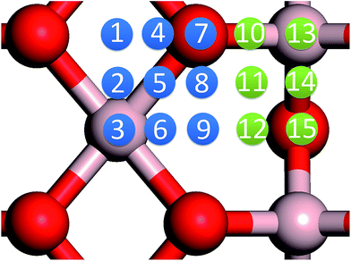
In our previous work, we placed an Au atom at fifteen sites (divided into two zones) distributed over a reduced quarter symmetric region of the (2 × 1) unit cell of the θ-Al2O3(001) surface (Fig. 3); we found that the adsorption energies for the flat area (zone 1, blue numbers) are generally 0.1 eV greater than those for the trench area (zone 2, green numbers).53 The O–Al bridge site (No. 5) in zone 1 is the most favored, with  = 0.35 eV. In the present work, a single Au atom was also placed on such an irreducible oxide surface but the oxide was supported with NiAl(100); the Au atom was allowed to relax to its energetically favored site. The most favored adsorption site is No. 3, a four-fold Al site in the flat zone, for all models except model 5L–O–Ni; the Au atom initially at any other asymmetric site migrated to this site after relaxation. The Au atom also adsorbed stably on sites No. 1 or 15 with smaller
  , because of their high symmetry (metastable positions). The adsorption properties in model 5L–O–Ni resemble those for the bulk θ-Al2O3(001) surface; their adsorption energies at site No. 3 (
 = 0.36 eV) and No. 5 (
 = 0.37 eV) are both comparable with those for the bulk θ-Al2O3(001) surface (
 = 0.32 and 0.35 eV respectively).53
 for an Au atom on stable site No. 3 in the various models are listed in Table 1; the values for adsorption on metastable site No. 15 are shown for comparison.
  in these models (except model 5L–O–Ni) are significantly greater (0.93–2.71 eV) than those for bulk θ-Al2O3 and are greater for thinner oxide films (1–3 atomic layers, 1.04–2.71 eV), indicating that
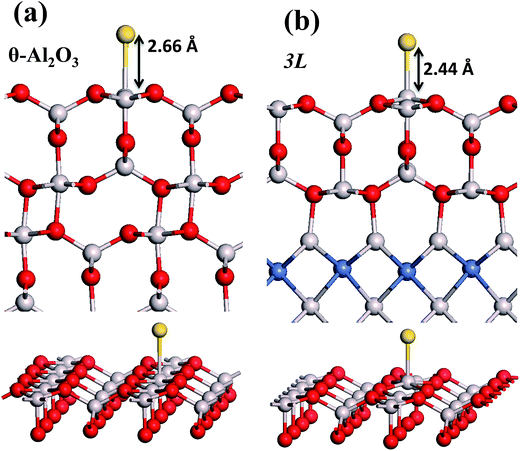
  is enhanced by the supporting NiAl. Several possible origins are discussed for this enhancement: structural relaxation, decreased work function, charge transfer and alteration of the density of states (DOS). We note first that the substrate structure alters significantly in response to the presence of the Au adsorbate. The Au-binding Al atom relaxes outwards, as shown in Fig. 4(a) and (b); its uplift distance, δAl, typically exceeds 0.30 Å (Table 2), evidently greater than that on a bulk θ-Al2O3 surface (0.07 Å) and in model 5L–O–Ni (0.09 Å). Additionally, the Au–Al bonds on a thin θ-Al2O3 film become shorter than that on the bulk (Fig. 4(a) and (b) and Table 2), reflecting typically stronger binding. Au in model 5L–O–Ni resembles Au on the bulk θ-Al2O3(001) surface in both the uplift distance δAl and the Au–Al bond length (Table 2), agreeing well with their similar
  .
.
The induced structural relaxation of Au involves not only the Au-binding Al but also other atoms around the Al atom. To estimate the contribution of the other relaxing atoms to the adsorption energy, we calculated  on fixing the atomic layers stepwise from NiAl to alumina films. Au in models 3L and 5L–O–Al, representing the greatest and least
  respectively, serves to demonstrate the effect of structural relaxation. The results show that the relaxation at all atomic layers contributes to the enhanced
  , whereas the relaxation at the atomic layers nearer the surface accounts more for
  (Table 3). For instance, the relaxation of the top three layers in models 3L and 5L–O–Al accounts for 35% and 31.2% of their
  , respectively. If all atoms in the alumina and NiAl were fixed,
  decreased by 41.3% and 49.5% for Au in models 3L and 5L–O–Al, respectively. They remained greater (1.59 eV in model 3L and 0.47 eV in 5L–O–Al) than that for bulk θ-Al2O3(001) (0.32 eV) or that in model 5L–O–Ni (0.36 eV). The structural relaxation shares a great proportion of the enhanced
  , but other mechanisms are also involved.
| Site No. 3 | |||||
|---|---|---|---|---|---|
| 3L | 5L–O–Al | ||||
| Fixed layers | % | Fixed layers | % | ||
| 3L Al2O3 + NiAl | 1.59 | 58.7 | 5L Al2O3 + NiAl | 0.47 | 50.5 |
| 2L Al2O3 + NiAl | 2.39 | 88.2 | 4L Al2O3 + NiAl | 0.65 | 69.9 |
| 1L Al2O3 + NiAl | 2.43 | 89.7 | 3L Al2O3 + NiAl | 0.68 | 73.1 |
| All NiAl substrate | 2.54 | 93.7 | 2L Al2O3 + NiAl | 0.76 | 81.7 |
| Bottom 3L of NiAl | 2.71 | 100.0 | 1L Al2O3 + NiAl | 0.87 | 93.5 |
| All NiAl substrate | 0.91 | 97.8 | |||
| Bottom 3L of NiAl | 0.93 | 100.0 | |||
We note that the work functions, listed in Table 2, of θ-Al2O3/NiAl(100) films are remarkably decreased; relative to the bulk θ-Al2O3 value, the work function in model 3L is decreased by 2.2 eV and even that in model 5L–O–Ni by 1.47 eV. This decreased work function facilitates charge transfer from the substrate to the Au adsorbate, as indicated for Au/MgO/Mo(100).18 The charge transferred from θ-Al2O3/NiAl(100) to the adsorbed Au atom, except model 5L–O–Ni, amounts to 0.20–0.26e (e = the charge of an electron), which is 4–5 times that (0.05e) on bulk θ-Al2O3 (Table 2). For all models except 1L, the charge transferred to the adsorbed Au is largely from the Au-binding Al and O atoms directly below the Al atom (Fig. 5(a) and (b)). This result confirms that the top layers are strongly involved in the interaction with the adsorbed Au. For model 1L, the transferred charge came primarily from the NiAl substrate, rather than the alumina film, illustrated in Fig. 5(c). As the alumina film in model 1L is thin and metallic (ESI†), the charge can tunnel readily through the alumina film. As a result, the charge transfer results in the formation of an Auδ− ion, induces an Au-surface dipole at the oxide surface and, hence, enhances the interaction between the adsorbed Au atom and the oxide surface.18,24,25
The enhanced adsorption energy is also reflected in the altered DOS of Au at the surface. For Au on site No. 3 of the bulk θ-Al2O3 surface, two peaks appear about 0.5 and 2.0 eV below the Fermi energy (Fig. 6(a)); in contrast, three features appear below the Fermi energy for Au on the θ-Al2O3/NiAl(100) surface and the additional signal (about 2.5 eV below the Fermi energy) decreased with increasing alumina layers (Fig. 6(b)–(h)). The additional signal is an effect from the supporting NiAl. Except model 5L–O–Ni, the effect also decreased the band gap between the highest occupied molecular orbital (HOMO) and the lowest unoccupied molecular orbital (LUMO) of the adsorbed Au atom, from 4.0 eV to 3.0–3.5 eV. The DOS of Au in model 3L (Fig. 6(e)) has a notably negative shift by about 1.0 eV; this great shift, consistent with a greatly enhanced  of Au in model 3L (Table 1), implies an increased interaction between Au and the θ-Al2O3/NiAl(100) surface.
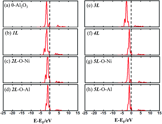 | ||
| Fig. 6 Calculated DOS for an adsorbed Au atom on (a) bulk θ-Al2O3(001) and (b)–(h) various θ-Al2O3/NiAl(100) surfaces, as indicated. The dashed lines in the figure indicate the Fermi energy. | ||
3. Adsorption of an Au dimer on the θ-Al2O3/NiAl(100) surface
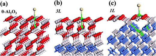
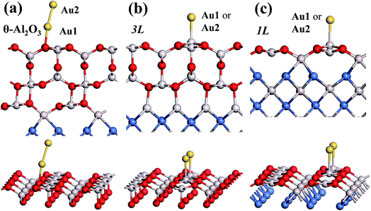
Our preceding work on an Au dimer on the bulk θ-Al2O3(001) surface showed that the dimer adsorbs preferentially with one Au bound to a surface O and the other dangling, as an end-on adsorption; both adsorption and cohesive energies alter little when the Au–O axis tilts slightly (within 30°) with respect to the surface normal or the standing dimer rotates azimuthally about the surface normal.53 Similar results are obtained for an Au2 dimer in models 2L, 4L and 5L; the Au dimer is singly coordinated to a surface O and with the Au–O axis tilted relative to the surface normal, shown in Fig. 7(a). Like the Au dimer on the bulk θ-Al2O3 surface, the Au-oxide bond length (DAu-oxide) decreases to 2.24–2.25 Å, whereas the Au–Au bond length (DAu–Au) remains at the value for a gaseous dimer, 2.52 Å; no adsorption-induced structural variation in the oxide film occurs. Their (0.7 ± 0.1 eV) or
  (1.50 ± 0.04 eV) are also similar (Table 4) and resemble those on the bulk θ-Al2O3 surface. No enhancement in the adsorption energy as great as that for a single Au atom (Table 2) is indicated for these oxide films.
| Model | DAu–Au/Å | DAu-oxide/Å | ΔQAu1/e | ΔQAu2/e | ||
|---|---|---|---|---|---|---|
| θ-Al2O3 | 0.74 | 1.51 | 2.52 | 2.25 | 0.10 | 0.05 |
| 1L | 1.24 | 1.76 | 2.69 | 2.49 | 0.11 | 0.11 |
| 2L–O–Ni | 0.63 | 1.46 | 2.52 | 2.24 | 0.08 | 0.05 |
| 2L–O–Al | 0.63 | 1.46 | 2.52 | 2.26 | 0.09 | 0.05 |
| 3L | 2.40 | 2.34 | 3.00 | 2.42 | 0.16 | 0.16 |
| 4L | 0.77 | 1.52 | 2.52 | 2.24 | 0.10 | 0.05 |
| 5L–O–Ni | 0.79 | 1.53 | 2.52 | 2.24 | 0.10 | 0.05 |
| 5L–O–Al | 0.73 | 1.50 | 2.51 | 2.25 | 0.10 | 0.05 |
The adsorption of an Au2 dimer on θ-Al2O3 slabs of one and three atomic layers on NiAl(100), models 1L and 3L, is disparate. Their most stable configurations have the dimers lying on the surfaces along direction [010], so side-on adsorption, and two Au atoms bound to the Al atoms on site No. 3 (Fig. 7(b) and (c)); the Au-bonding Al atoms are both lifted in a manner similar to that of the Al atom bound to an adsorbed single Au atom (Fig. 4(b)). The Au dimer on the 3L surface has the greatest  (2.40 eV), comparable with
  (2.34 eV), and the largest DAu–Au (3.0 Å). The energetics and adsorption configuration imply that the Au-oxide interaction is so strong that the Au–Au bonding becomes ineffective. The Au2 dimer on the 1L surface also shows great
  (1.24 eV) and
  (1.76 eV). The smaller DAu–Au (2.69 Å) nevertheless reflects an effective dimer bonding, consistent with its
  being greater than
  . The evidently distinct adsorption configurations and energies in models 1L and 3L indicate a dimer-surface interaction different from those in the other alumina models. The Au2 dimers placed in structurally symmetric configurations do not relax to the above stable configurations but remain as they are initially placed. For instance, the flat-lying dimer with its Au on site No. 15–No. 15 remains as that configuration because of the structurally symmetric constraints.
  for such symmetric configurations are smaller than 0.1 eV. Some metastable adsorption with an asymmetric configuration might form but also have a small
  . Examples are given in the ESI.†
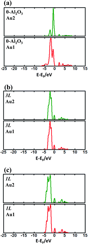
To investigate the adsorption properties of an Au dimer on thin oxide films, we analyzed their charge transfer and DOS. The transferred charge of an Au dimer on various θ-Al2O3/NiAl(100) surfaces is listed in Table 4. For an Au dimer standing upright (on bulk θ-Al2O3 and alumina films in models 2L, 4L and 5L), the charge transferred to the Au bound to O (Au1) amounts to 0.08–0.1e (ΔQAu1) whereas that for the Au dangling (Au2) is only 0.05e (ΔQAu2). Consistently, the DOS of Au1 differs from that of Au2, as shown in Fig. 8(a); Au1 has a main maximum at 3.0 eV below the Fermi level but Au2 has its main DOS maximum near the Fermi level. Similar results are obtained for the dimer on bulk θ-Al2O3 and alumina films in models 2L, 4L and 5L. The DOS of neither Au1 nor Au2 resembles that for a single Au atom (Fig. 6). As the Au–Au bonding alters the adsorption properties, the adsorption site, adsorption energy, DOS and charge transfer of an Au dimer all differ from those of a single Au atom in these models.
For models 1L and 3L, the transferred charge becomes greater (Table 4) – ΔQAu1 = ΔQAu2 = 0.16e in model 3L and ΔQAu1 = ΔQAu2 = 0.10e in model 1L, but is still smaller than their single-atom counterparts (Table 2). The DOS of Au1 and Au2 in models 1L and 3L are the same (Fig. 8(b) and (c)), indicating equivalent atoms, but unlike their single-atom counterparts (Fig. 6). For instance, the DOS of an Au dimer in model 1L has two major maxima: one at −2.0 eV and the other at −4.0 eV (Fig. 8(c)); it resembles neither those of Au dimers on other models nor that of a single Au on θ-Al2O3(1L)/NiAl(100) (Fig. 6(b)). This result indicates that, although the Au–Au bond is weakened and the dimer in model 3L adsorbs like two separate Au atoms, the electronic structure of Au is substantially altered by the second Au. The thickness-dependent adsorption configuration is likely associated with 2D structures and a bimodal distribution of the size of Au clusters observed on Al2O3/NiAl(100).44 On 1L and 3L Al2O3/NiAl(100), deposited Au atoms apparently tend to form 2D clusters at initial stages; the clusters grown through such an atomic stacking are expected to have a (001) orientation in a fcc phase, which also agree with the measured atomic structure of the Au clusters.40,54
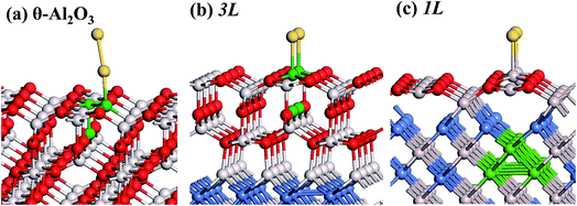
The substrate atoms involved in the charge transfer are found to corroborate the above argument for the Au-surface interactions. For the case of upright-standing configurations, the charge is transferred largely from Au-binding O (site No. 7), neighboring Al (site No. 3) and O below site No. 3, as shown in Fig. 9(a), differing from their single-atom counterparts (Fig. 5(a)–(c)). For an Au dimer in model 3L, the charge is transferred mostly from Au-binding Al (site No. 3) and O below site No. 3 (Fig. 9(b)), resembling that for a single Au atom in model 3L (Fig. 5(b)). For an Au dimer in model 1L, the charge transfers largely from the NiAl to the adsorbed dimer (Fig. 9(c)), a feature similar to that for an Au atom on θ-Al2O3(1L)/NiAl(100) (Fig. 5(c)), indicating that the adsorbed Au interacts substantially with the NiAl substrate underlying the monolayer alumina. These results again reflect that the adsorption of an Au monomer and dimer on θ-Al2O3(3L and 1L)/NiAl(100) indeed has some common properties. According to the above analysis, whether or not an adsorbed dimer lies flat on the θ-Al2O3(001)/NiAl(100) depends on a competition between the Au-oxide interaction and Au–Au bonding. A single Au atom preferentially adsorbed on site No. 3 but the distance between adjacent two sites No. 3 is greater than the natural Au–Au bond length (the bond length in the gas phase). When a dimer lies flat on the oxide surface with its two Au atoms bound to adjacent sites No. 3, it must have an increased bond length and thus a weakened Au–Au bond as an expense. If the strong Au-oxide interaction can compensate the raised energy due to the weakened Au–Au bond, the flat-lying geometry becomes energetically preferred; otherwise, the upright geometry, for which the Au–Au bond strength is sustained, is preferred. In model 1L and 3L, the Au-oxide interaction is sufficiently strong to afford the flat-lying geometry.
Conclusion
With DFT calculations, we have investigated the adsorption of a single Au atom and a dimer on thin θ-Al2O3(001) films, with thickness varying from one to five atomic layers (1L–5L), supported on NiAl(100). The adsorption behavior in a model with film thickness 5L resembles that on the bulk θ-Al2O3(001) surface, whereas the others differ and vary with the film thickness. A single Au atom on the bulk θ-Al2O3(001) surface, in an armchair-like configuration comprising flat and trench areas, adsorbs preferentially on the O–Al bridge site in the flat zone (0.32 eV); in contrast, the atom on 1L–4L thick θ-Al2O3/NiAl(100) is bound to the surface Al in the flat zone, with significantly enhanced adsorption energies (≥0.94 eV). The enhancement is accompanied by a shortened Au-oxide bond and an uplifted Au-binding Al (relative to that on the bulk θ-Al2O3(001) surface). The structural relaxation accounts largely, but incompletely, for the enhanced adsorption energies. Our electronic analysis indicates that the work function which is decreased because of the alumina–NiAl interfacial interaction promotes a transfer of charge from the oxide substrate to an adsorbed Au atom, and thus the interaction between the substrate and that Au atom. For 1L θ-Al2O3/NiAl(100), the charge tunnels readily from NiAl to the adsorbed Au. The promoted Au-substrate interaction is reflected also in the decreased HOMO–LUMO band gap and negatively shifted DOS of an adsorbed Au. For an Au dimer adsorbed on the θ-Al2O3/NiAl(100) surface, stable configurations of two kinds are indicated; on 2L, 4L and 5L alumina films, the dimer adsorbs preferentially in an upright (end-on) geometry, with one Au bound to a surface O and the other dangling, resembling that on a bulk θ-Al2O3 surface, whereas on 1L and 3L ones, the dimer lies flat on the oxide surface (side-on), with its Au–Au bond axis along direction [010] and the two Au atoms bound to the surface Al atoms in the flat zone. The latter adsorbs like two separate Au atoms and has an evidently greater adsorption energy, as the Au-oxide interaction becomes so dominating that the altered energy due to the weakened Au–Au bond, indicated by an increased Au–Au bond length and diminished difference between adsorption and cohesive energies, becomes minor.Conflicts of interest
There are no conflicts to declare.Acknowledgements
National Science Council in Taiwan provided financial support (grants NSC-98-2112-M-008-015-MY2 and NSC-100-2112-M-008-010-MY3) for this work. We thank Yi-Cheng Huang for technical support.References
- C. T. Campbell, Surf. Sci. Rep., 1997, 27, 1–111 CrossRef CAS.
- C. R. Henry, Surf. Sci. Rep., 1998, 31, 231–325 CrossRef CAS.
- X. Lai, T. P. S. Clair, M. Valden and D. W. Goodman, Prog. Surf. Sci., 1998, 59, 25–52 CrossRef CAS.
- M. Bäumer and H.-J. Freund, Prog. Surf. Sci., 1999, 61, 127–198 CrossRef.
- A. K. Santra and D. W. Goodman, J. Phys.: Condens. Matter, 2003, 15, R31 CrossRef CAS.
- H.-J. Freund, Surf. Sci., 2002, 500, 271–299 CrossRef CAS.
- M. Haruta, Catal. Today, 1997, 36, 153–166 CrossRef CAS.
- M. Valden, X. Lai and D. W. Goodman, Science, 1998, 281, 1647 CrossRef CAS PubMed.
- D. W. Goodman, J. Phys. Chem., 1996, 100, 13090–13102 CrossRef CAS.
- D. R. Rainer, C. Xu and D. W. Goodman, J. Mol. Catal. A: Chem., 1997, 119, 307–325 CrossRef CAS.
- V. Nehasil, I. Stará and V. Matolín, Surf. Sci., 1995, 331–333, 105–109 CrossRef CAS.
- S. Andersson, M. Frank, A. Sandell, A. Giertz, B. Brena, P. A. Brühwiler, N. Mårtensson, J. Libuda, M. Baümer and H. J. Freund, J. Chem. Phys., 1998, 108, 2967–2974 CrossRef CAS.
- J. M. Flores-Camacho, J. H. Fischer-Wolfarth, M. Peter, C. T. Campbell, S. Schauermann and H. J. Freund, Phys. Chem. Chem. Phys., 2011, 13, 16800–16810 RSC.
- M. Peter, J. M. Flores Camacho, S. Adamovski, L. K. Ono, K.-H. Dostert, C. P. O'Brien, B. Roldan Cuenya, S. Schauermann and H.-J. Freund, Angew. Chem., Int. Ed., 2013, 52, 5175–5179 CrossRef CAS PubMed.
- T.-C. Hung, T.-W. Liao, Z.-H. Liao, P.-W. Hsu, P.-Y. Cai, H. Lee, Y.-L. Lai, Y.-J. Hsu, H.-Y. Chen, J.-H. Wang and M.-F. Luo, ACS Catal., 2015, 5, 4276–4287 CrossRef CAS.
- M. Sterrer, M. Yulikov, E. Fischbach, M. Heyde, H.-P. Rust, G. Pacchioni, T. Risse and H.-J. Freund, Angew. Chem., Int. Ed., 2006, 45, 2630–2632 CrossRef CAS PubMed.
- G. Pacchioni, L. Giordano and M. Baistrocchi, Phys. Rev. Lett., 2005, 94, 226104 CrossRef PubMed.
- L. Giordano and G. Pacchioni, Phys. Chem. Chem. Phys., 2006, 8, 3335–3341 RSC.
- M. Sterrer, T. Risse, U. Martinez Pozzoni, L. Giordano, M. Heyde, H.-P. Rust, G. Pacchioni and H.-J. Freund, Phys. Rev. Lett., 2007, 98, 096107 CrossRef PubMed.
- F. Calaza, C. Stiehler, Y. Fujimori, M. Sterrer, S. Beeg, M. Ruiz-Oses, N. Nilius, M. Heyde, T. Parviainen, K. Honkala, H. Häkkinen and H.-J. Freund, Angew. Chem., Int. Ed., 2015, 54, 12484–12487 CrossRef CAS PubMed.
- C. P. O'Brien, K. H. Dostert, M. Hollerer, C. Stiehler, F. Calaza, S. Schauermann, S. Shaikhutdinov, M. Sterrer and H. J. Freund, Faraday Discuss., 2016, 188, 309–321 RSC.
- N. Nilius, E. D. L. Rienks, H.-P. Rust and H.-J. Freund, Phys. Rev. Lett., 2005, 95, 066101 CrossRef PubMed.
- L. Giordano, G. Pacchioni, J. Goniakowski, N. Nilius, E. D. L. Rienks and H.-J. Freund, Phys. Rev. Lett., 2008, 101, 026102 CrossRef PubMed.
- D. Ricci, A. Bongiorno, G. Pacchioni and U. Landman, Phys. Rev. Lett., 2006, 97, 036106 CrossRef PubMed.
- M. Sterrer, T. Risse, M. Heyde, H.-P. Rust and H.-J. Freund, Phys. Rev. Lett., 2007, 98, 206103 CrossRef PubMed.
- M. Haruta, N. Yamada, T. Kobayashi and S. Iijima, J. Catal., 1989, 115, 301–309 CrossRef CAS.
- G. C. Bond and D. T. Thompson, Catal. Rev., 1999, 41, 319–388 CAS.
- D. Cameron, R. Holliday and D. Thompson, J. Power Sources, 2003, 118, 298–303 CrossRef CAS.
- M. Haruta, A. Ueda, S. Tsubota and R. M. Torres Sanchez, Catal. Today, 1996, 29, 443–447 CrossRef CAS.
- F. Boccuzzi, A. Chiorino and M. Manzoli, J. Power Sources, 2003, 118, 304–310 CrossRef CAS.
- F.-W. Chang, H.-Y. Yu, L. S. Roselin, H.-C. Yang and T.-C. Ou, Appl. Catal., A, 2006, 302, 157–167 CrossRef CAS.
- P. Gassmann, R. Franchy and H. Ibach, Surf. Sci., 1994, 319, 95–109 CrossRef CAS.
- R.-P. Blum, D. Ahlbehrendt and H. Niehus, Surf. Sci., 1998, 396, 176–188 CrossRef.
- V. Maurice, N. Frémy and P. Marcus, Surf. Sci., 2005, 581, 88–104 CrossRef CAS.
- M. S. Zei, C. S. Lin, W. H. Wen, C. I. Chiang and M. F. Luo, Surf. Sci., 2006, 600, 1942–1951 CrossRef CAS.
- M. F. Luo, C. I. Chiang, H. W. Shiu, S. D. Sartale and C. C. Kuo, Nanotechnology, 2006, 17, 360 CrossRef CAS.
- H. Qin and G. Zhou, J. Appl. Phys., 2013, 114, 083513 CrossRef.
- H. Qin, P. Sutter and G. Zhou, J. Am. Ceram. Soc., 2014, 97, 2762–2769 CrossRef CAS.
- H. Qin, X. Chen, L. Li, P. W. Sutter and G. Zhou, Proc. Natl. Acad. Sci. U. S. A., 2015, 112, E103–E109 CrossRef CAS PubMed.
- S. D. Sartale, H.-W. Shiu, M.-H. Ten, W.-R. Lin, M.-F. Luo, Y.-C. Lin and Y.-J. Hsu, J. Phys. Chem. C, 2008, 112, 2066–2073 CAS.
- C.-S. Chao, Y.-D. Li, B.-W. Hsu, W.-R. Lin, H.-C. Hsu, T.-C. Hung, C.-C. Wang and M.-F. Luo, J. Phys. Chem. C, 2013, 117, 5667–5677 CAS.
- N. Frémy, V. Maurice and P. Marcus, J. Am. Ceram. Soc., 2003, 86, 669–675 CrossRef.
- V. Simic-Milosevic, M. Heyde, N. Nilius, T. König, H. P. Rust, M. Sterrer, T. Risse, H. J. Freund, L. Giordano and G. Pacchioni, J. Am. Chem. Soc., 2008, 130, 7814–7815 CrossRef CAS PubMed.
- M. F. Luo, H. W. Shiu, M. H. Ten, S. D. Sartale, C. I. Chiang, Y. C. Lin and Y. J. Hsu, Surf. Sci., 2008, 602, 241–248 CrossRef CAS.
- G. Kresse and J. Hafner, Phys. Rev. B: Condens. Matter Mater. Phys., 1993, 47, 558–561 CrossRef CAS.
- G. Kresse and J. Furthmüller, Comput. Mater. Sci., 1996, 6, 15–50 CrossRef CAS.
- G. Kresse and J. Furthmüller, Phys. Rev. B: Condens. Matter Mater. Phys., 1996, 54, 11169–11186 CrossRef CAS.
- G. Kresse and D. Joubert, Phys. Rev. B: Condens. Matter Mater. Phys., 1999, 59, 1758–1775 CrossRef CAS.
- J. P. Perdew, K. Burke and M. Ernzerhof, Phys. Rev. Lett., 1996, 77, 3865–3868 CrossRef CAS PubMed.
- J. Ho, K. M. Ervin and W. C. Lineberger, J. Chem. Phys., 1990, 93, 6987–7002 CrossRef CAS.
- A. Stierle, V. Formoso, F. Comin and R. Franchy, Surf. Sci., 2000, 467, 85–97 CrossRef CAS.
- E. Husson and Y. Repelin, Eur. J. Solid State Inorg. Chem., 1996, 33, 1223–1231 CAS.
- B. W. Chang, J. P. Chou and M. F. Luo, Surf. Sci., 2011, 605, 1122–1128 CrossRef CAS.
- G.-R. Hu, C.-S. Chao, H.-W. Shiu, C.-T. Wang, W.-R. Lin, Y.-J. Hsu and M.-F. Luo, Phys. Chem. Chem. Phys., 2011, 13, 3281–3290 RSC.
Footnote |
| † Electronic supplementary information (ESI) available. See DOI: 10.1039/c7ra13081c |
| This journal is © The Royal Society of Chemistry 2018 |

