 Open Access Article
Thermal debinding mass transfer mechanism and dynamics of copper green parts fabricated by an innovative 3D printing method
Xiaokang Yan*a,
Chao Wangb,
Wei Xionga,
Tongwei Houc,
Liang Hao *a and
Danna Tanga
aGemological Institute, China University of Geosciences, Wuhan, 430074, Chian. E-mail: cugxky@163.com; haoliang4883@outlook.com; Fax: +86 27 87482950; Tel: +86 27 67884883
bZhengzhou Vocational University of Information and Technology, Zhengzhou, 450046, China
cSchool of Materials Science and Engineering, North University of China, Taiyuan, 030051, China
First published on 14th March 2018
Abstract
To explore the thermal debinding mass transfer mechanism and dynamics of an innovative copper paste injection 3D printing method, the thermal behavior of the copper paste was investigated to clarify the stages of the debinding process. Furthermore, the debinding ratio, burnout ratio, shrinkage and microstructures were characterized to study the mass transfer channel and dynamics. The dynamics equation of diffusion mass transfer was analyzed. The activation energy and pre-exponential factor were calculated. The results revealed that gas phase mass transfer was the main mass transfer path and the diffusion coefficient in the carbon powder embedded environment (2.68 × 10⁻⁵ cm2 s−1) was higher than that in air atmosphere (1.96 × 10⁻⁵ cm2 s−1). Moreover, the migration of solid phase materials and the diffusion of atoms are also discussed. When combined with the sintering process, the sintered metal parts had a smooth surface flatness and excellent metallurgical bonding, the thin wall of which was only 340 μm thick.
1 Introduction
Metal 3D printing technologies such as laser micro sintering (LMS), selective laser melting (SLM) and electron beam melting (EBM) are capable of manufacturing metal components with complex structures and advanced functionalities1,2 and have been widely applied in aviation, medical and other high-end fields.3–5 However, the extremely fast conditions during the laser or electron beam melt-forming process often makes it easy to form crack defects, severely affecting the mechanical properties. A recent study reported that the use of a nano zirconium-based nucleating agent to assemble alloy powder can effectively inhibit micro-cracks and improve the strength of the alloy.6 However, this very innovative tool still cannot completely solve the problems of the limited range of printable materials and extremely expensive equipment that have existed for a long time.7To avoid these problems, a low-cost 3D printing technique via metal paste injection 3D printing was developed. It involves the use of the material deposition principle for forming a 3D shape layer-by-layer, similar to the fused deposition modeling (FDM).8,9 However, it requires a debinding and sintering process to remove the adhesive material and consolidate the metallic materials. A specific binder wax material is mixed with fine metal particles to formulate paste composite, which is then heated to form a semi-melt paste and injected from the fine deposition nozzle; then, the injected material is cooled and solidified layer-by-layer to form 3D shapes. Then, the green part is heated in an oven to vaporize the binder during the debinding stage and the remaining powder is sintered into a dense part, similar to the process of metal injection molding (MIM).10,11 As the use of a mold is not required, our method shows a clear advantage over MIM in terms of complex metallic structure fabrication. In this study, the main research purpose was to explore the mass transfer mechanism and dynamics during the debinding process.
As a new and emerging technology, it requires further research regarding basic scientific problems. The related studies reported that a 3D printer with an extrusion device could be used to deposit copper powder and polymer paste with high viscosity to form metal parts.12–14 Thus, the feasibility of our method has been initially confirmed, but there was no systematic discussion of the forming process and mechanism, particularly the essential debinding process such as MIM. Therefore, to guide the production of metal components with high performance, the basic scientific problems of debinding and the sintering mechanism should be clarified. In this study, the debinding process is extremely important for forming 3D metal structures. If the debinding process parameters such as the excessive heating rate and the short holding time are not properly controlled, it would cause cracks or bubbling of metal components and even make it impossible to remove the complex metal 3D structure. Because the diffusion of metal atoms does not occur on a large scale in the debinding stage, the bonding between particles is physical and thus, the mechanical properties are not strong. Therefore, revealing the law of changes in physical and chemical properties of the green part is helpful in controlling the debinding process, which plays a crucial role in the manufacture of metal and alloy components. It is not hard to understand that during the debinding process, a series of basic physical changes and chemical reactions occurs, such as melting and vaporization of adhesives, decomposition of adhesives, migration and diffusion of adhesives under different physical states as well as the diffusion of adhesive decomposition products. To explore these basic scientific issues, the mass transfer mechanism and dynamics during the debinding process were mainly investigated quantitatively in this study.
For a discussion of the debinding problems, there are literature reports that can be referred to,15–17 most of which were published in the field of MIM (mentioned above). However, most studies focused on the relationship between debinding process parameters and the properties of sintered parts and rarely involved analysis of the mass transfer mechanism and dynamic problems. Nevertheless, the process of debinding kinetics is the fundamental basis for determining the heating system in the MIM debinding process.18 The existing basic theories regarding the dynamics of the debinding of MIM mainly include Young's equation19, Fick's law20 and Vetter's equation21, providing the theoretical foundation for this study. Unlike MIM technology, however, metal paste injection 3D printing technology does not use molds and is not stressed, so unlike MIM, whether the surface interface conditions of the material systems in this study and smaller and more complex dimensions of the green part shape will bring interesting results remains to be explored. Nevertheless, we insist that the basic theory of debinding dynamics mentioned above in MIM can be used to explain debinding in metal paste injection 3D printing and it has some innovation in research of the topic, which has not been reported in the related field of 3D printing till date.
In this study, paraffin wax was selected as the binder to prepare the copper paste. The debinding experiment was carried out with embedded carbon powder. The mass transfer mechanism and dynamics problems were analyzed and discussed as key topics. In addition, the migration of solid phase materials and the diffusion of metal atoms were considered creatively.
2 Experiment
Copper powder with average size of 1 μm (purity >99.5%) and paraffin wax (0.9 g cm−3) were mixed to prepare copper paste according to the mass ratio of powder to paraffin (m1![[thin space (1/6-em)]](https://www.rsc.org/images/entities/char_2009.gif) :
:![[thin space (1/6-em)]](https://www.rsc.org/images/entities/char_2009.gif) m2) of 10
m2) of 10![[thin space (1/6-em)]](https://www.rsc.org/images/entities/char_2009.gif) :
:![[thin space (1/6-em)]](https://www.rsc.org/images/entities/char_2009.gif) 1 based on the closest packing principle.22
1 based on the closest packing principle.22
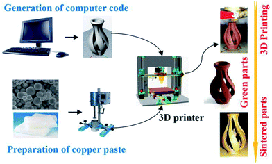
A laboratory-based equipment was built for the experiment comprising a 3D printer and a syringe with a nozzle (0.4 mm in diameter). The paste was prepared with a preparation device that agitated and heated the mixed materials at 70–80 °C, following which the paste was printed as per the software. The printing process is summarized in Fig. 1.
After printing, the green parts were placed in a muffle furnace (SX2-5-12, China) under the condition of carbon powder-embedding to explore the debinding process. Using 10 mg printed paste, thermogravimetric analysis (TG-DSC, STA449F3, Germany) was performed under N2 atmosphere (30 mL min−1) with experimental range 20–1050 °C and heating rate 10 °C min−1. The microstructures of the samples were observed using a field emission scanning electron microscope (FE-SEM, SU8010, Hitachi, Japan) equipped with energy spectrometer. Before energy spectrum analysis, the sample was corroded using a mixture of FeCl3·6H2O (analytical grade, 5 g), nitric acid (5 mol L−1, 50 mL) and deionized water (100 mL), following which the sample was washed several times with deionized water. In addition to the debinding ratio, the shrinkage and burnout ratio of the samples were also investigated. Herein, debinding ratio refers to the ratio of binder removed relative to the total binder, while burnout ratio refers to the ratio of binder removed to the total copper paste.
3 Results and discussion
3.1 Debinding mechanism and mass transfer pathways
The TG curve (Fig. 2a) shows that the debinding process progressed through three main stages. The sample exhibited slight weight loss at 200 °C, indicating that the wax present on the paste surface started to melt and that the removal of wax was initiated. From 200 to 300 °C, the sample demonstrated severe weight loss, implying that the main stage of paraffin decomposition and removal occurred during this heating phase. As the temperature increased from 300 to 400 °C, the sample exhibited slight weight loss, indicating the end of paraffin decomposition. Beyond 400 °C, the sample quality was almost unchanged. In thermogravimetric experiments, the endothermic/exothermic value of the material system can be characterized through differential scanning calorimetry (DSC), the principle of which is to measure the relationship between the power (heat flow rate) difference between the sample and a reference versus temperature.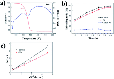 | ||
| Fig. 2 Debinding mechanism and dynamics analysis: (a) TG–DTA curve of the sample; (b) debinding ratio curve of the sample; (c) fitting curve between ln(1/F) and t/Ψ2. | ||
By characterizing the debinding ratio, we mainly analyzed the mass transfer pathways during debinding at 300 °C due to the most complicated mass transfer mechanism at this time. It can be found that when the temperature was 300 °C, the adhesive in the sample decomposed into a gas. Therefore, gas-phase mass transfer pathways were generally the process by which the gas-phase product discharged the sample from the inside to the outside, and the specific pathways included: (1) diffusion of paraffin-decomposed gas phase product in liquid paraffin; (2) diffusion of the paraffin-decomposed gas-phase product through previously formed pores; (3) spread of vaporized product of paraffin in liquid paraffin. Due to the embedded carbon powder, the mass transfer path also included liquid mass transfer, which was liquid phase migration under capillary forces.
The debinding ratio curve over time with embedded carbon powder and air environments are illustrated in Fig. 2b. The debinding ratio demonstrated a rising trend with time, but the debinding ratio with embedded carbon powder was slightly higher than that in air atmosphere; the difference contributed by the liquid phase migration under capillary forces could be neglected (Fig. 2b), indicating that the gas-phase mass transfer played a leading role in the debinding process.
3.2 Analysis of debinding diffusion mass transfer dynamics
 | (1) |
 | (2) |
 | (3) |
 | (4) |
| Deb. environment | Carbon | Air |
|---|---|---|
| di/(×10−5 cm2 s−1) | 2.68 | 1.96 |
| Adj. R-Squa. | 0.971 | 0.97 |
| Binder → volatile + residue | (5) |
Based on the kinetics of the non-isothermal thermogravimetric loss curve during debinding of MIM, the dynamics mechanism (eqn (5)) can be expressed as eqn (6):24,25
 | (6) |
 and 1/T show a linear relationship, so E and A can be calculated from the slope and intercept via fitting. In this study, it was assumed that the reaction order was 1 (n = 1) and the fitting results are exhibited in Fig. 3b and Table 2. It can be found that Adj. R-Squa. was 0.9121, showing a good linear relationship, implying that it was reasonable to assume that the reaction order was 1.
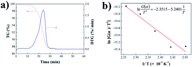 | ||
Fig. 3 Calculation of activation energy and pre-exponential factor: (a) the thermogravimetric and weight loss rate curves for the copper paste; (b) the fitting curve between  and 1/T. and 1/T. | ||
| Dynamics parameters | E (kJ mol−1) | A (min−1) | Adj. R-Square |
|---|---|---|---|
| Value | 43.57 | 4989 | 0.9121 |
3.3 The migration of solid phase materials and the diffusion of atoms
In the macroscopic process, the debinding process shows volume shrinkage and loss of quality. In addition to the gas-phase and the liquid-phase mass transfer at the microscopic level, the migration of copper powder and the diffusion of copper atoms in the initial stage of sintering are also included. Even in studies of MIM debinding, although limited data is available to explore the migration of solid particles, it is of critical importance to the dimensional accuracy of the metal components. In this study, the deficiencies in this aspect were corrected.When the temperature was 200 °C, the volume of the sample did not change and the burnout ratio was 3.95% (Fig. 4a and b), indicating that only gas phase or liquid phase mass transfer occurred at this stage and the positions of copper particles in the sample did not change. From 200 to 300 °C, the burnout ratio and shrinkage increased significantly and the debinding rate reached 91.8% (Fig. 4a and b), revealing that the distance between the particles shortened, resulting in a macro volume change. The subsequent burnout ratio did not change significantly, while the shrinkage was almost unchanged, implying that this stage was the critical point for the transition from copper particle migration to copper atom diffusion. Simultaneously, it is exhibited that when the temperature was in the range 500–600 °C, the sample clearly shrank, implying that a sintered neck between the particles was gradually formed, at which time the initial diffusion of copper atoms occurred. Unfortunately, the above material migration process cannot be quantified using a simple model due to the lack of an effective theoretical basis. However, the mass transfer of the above-mentioned gas phase, liquid phase and solid phase materials can be described as shown in Fig. 4c.
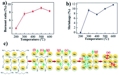 | ||
| Fig. 4 Analysis of the migration of solid phase materials and mass transfer model: (a) burnout ratio curve of the sample; (b) shrinkage curve of the sample. (c) Mass transfer model. | ||
3.4 Microstructure evolution during debinding process
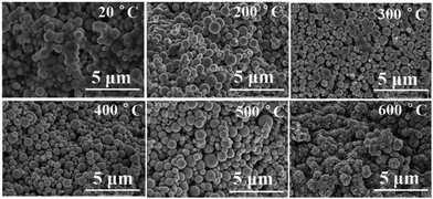
The above mentioned results and the extrapolation could be confirmed from the microstructures of the samples at different temperatures (Fig. 5). It can be seen that the paraffin was gradually removed and the regular spherical copper particles became clearer with an increase in temperature. When it reached 500 °C, powder with smaller diameter particles began to deform, slowly forming a sintered neck. On further increasing the temperature, all copper particles were sintered together and a large number of gaps could be observed in the structure. In the early stage of debinding, with the removal of paraffin, the initially dense microstructure of the sample became loose when the particles were simply physically bound. Subsequently, with the formation of the sintering neck the microstructure of the sample became dense again and the microstructure of the metal exhibited a metallurgical bonding mode.3.5 The performance of sintered part
The above debinding process may not remove all the paraffin wax, but this can be completed by the sintering process, which is another important issue mentioned briefly in this study. On sintering at 1000 °C, it is clear that the sample had smooth surface flatness with superior metallurgical bonding. The thin wall of the sample was only 340 μm thick (Fig. 6a). After testing, the hardness of the sintered parts was 80 HV and the density was 8.1 g cm−3. In addition, carbon was not found by the analysis of the SEM spectrum (Fig. 6b), indicating that the paraffin wax had been completely removed. Due to the use of ferric chloride solution in nitric acid (which was probably not cleaned later in the corrosion test), the experimental results also indicate the presence of Cl (Fig. 6b). In summary, metal paste injection 3D printing provides a new idea for the fabrication of complex 3D metal and alloy components by means of a low cost manufacturing method.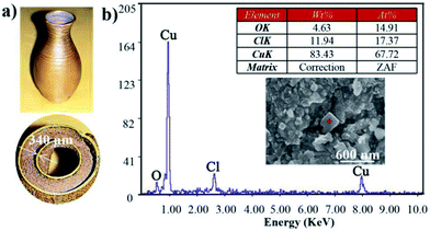 | ||
| Fig. 6 The performance of sintered part: (a) sintered samples; (b) SEM images of sintered samples with energy spectral analysis. | ||
4 Conclusions
The mass transfer pathways of thermal debinding included liquid mass transfer under the capillary force and gas-phase mass transfer, but the dominant role was that of the gas-phase mass transfer. The diffusion mass transfer equation could effectively describe the debinding process in air atmosphere and when carbon powder was embedded. The diffusion coefficient quantitatively described the mass transfer processes such as thermal cracking, oxidative cracking and liquid phase volatilization. Material migration during the thermal debinding process was reflected in the macroscopic volume and microstructure evolution of the components. With removal of the adhesive, the sample changed from dense to loose and then to dense, during which time a transition from physical bonding to metallurgical bonding took place. Combined with the sintering process, the sintered metal parts had smooth surface flatness and excellent metallurgical bonding; the thin wall of the part was only 340 μm thick.Conflicts of interest
There are no conflicts to declare.Acknowledgements
We gratefully acknowledge the financial support by National Natural Science Foundation of China (Grant No. 51675496 and 51671091), Wuhan City Applied Basic Research Project, China (No. 2017010201010126). This paper is CJHI contribution CJHIWZ-2017006. The authors acknowledge the financial support of a Grant (CJHIXM-S201617) from Center for Jewelry Heritage and Innovation, a Hubei Provincial Key Research Base for Humanity and Social Sciences.References
- M. Vaezi, H. Seitz and S. Yang, A review on 3D micro-additive manufacturing technologies, Int. J. Adv. Des. Manuf. Technol., 2013, 5, 1721–1754 CrossRef.
- L. Hirt, A. Reiser, R. Spolenak and T. Zambelli, Additive Manufacturing of Metal Structures at the Micrometer Scale, Adv. Mater., 2017, 29, 1604211 CrossRef PubMed.
- S. L. Taylor, R. N. Shah and D. C. Dunand, Ni–Mn–Ga micro-trusses via sintering of 3D-printed inks containing elemental powders, Acta Mater., 2018, 143, 20–29 CrossRef CAS.
- X. Yan, L. Hao, W. Xiong and D. Tang, Research on influencing factors and its optimization of metal powder injection molding without mold via an innovative 3D printing method, RSC Adv., 2017, 87, 55232–55239 RSC.
- X. Wang, L. N. Carter, B. Pang, M. M. Attallah and M. H. Loretto, Microstructure and yield strength of SLM-fabricated CM247LC Ni-Superalloy, Acta Mater., 2017, 128, 87–95 CrossRef CAS.
- J. H. Martin, B. D. Yahata, J. M. Hundley, J. A. Mayer and T. A. Schaedler, 3D printing of high-strength aluminium alloys, Nature, 2017, 549, 365–369 CrossRef CAS PubMed.
- Z. C. Cordero, H. M. Meyer, P. Nandwana and R. R. Dehoff, Powder bed charging during electron-beam additive manufacturing, Acta Mater., 2017, 124, 437–445 CrossRef CAS.
- Q. Hu, W. Li, H. Zhang, D. Liu, F. Peng and Y. Duan, Research into topology optimization and the FDM method for a space cracked membrane, Acta Astronaut., 2017, 136, 443–449 CrossRef CAS.
- A. Salea, R. Prathumwan, J. Junpha and K. Subannajui, Metal oxide semiconductor 3D printing: preparation of copper(II) oxide by fused deposition modelling for multi-functional semiconducting applications, J. Mater. Chem. C, 2017, 5, 4614–4620 RSC.
- R. M. German, Progress in Titanium Metal Powder Injection Molding, Materials, 2013, 6, 3641–3662 CrossRef PubMed.
- A. D. Manshadi, M. Bermingham, M. Dargusch and D. Stjohn, Metal Injection Moulding of Titanium and Titanium Alloys: Challenges and Recent Development, Powder Technol., 2017, 319, 289–301 CrossRef.
- S. Hwang, E. I. Reyes, K. S. Moon, R. C. Rumpf and N. S. Kim, Thermo-Mechanical Characterization of Metal/Polymer Composite Filaments and Printing Parameter Study for Fused Deposition Modeling in the 3D Printing Process, J. Electron. Mater., 2015, 44, 771–777 CrossRef CAS.
- S. Hong, C. Sanchez, H. Du and N. Kiml, Fabrication of 3D Printed Metal Structures by Use of High-Viscosity Cu Paste and a Screw Extruder, J. Electron. Mater., 2015, 44, 836–841 CrossRef CAS.
- C. Xu, A. Bouchemit, G. L. Espérance, L. L. Lebela and D. Therriault, Solvent-cast based metal 3D printing and secondary metallic infiltration, J. Mater. Chem. C, 2017, 5, 10448–10455 RSC.
- L. Gorjan, G. Blugan and T. Graule, Effectiveness of wick-debinding inside powder bed for ceramic laminates made by tape casting, Powder Technol., 2015, 273, 197–202 CrossRef CAS.
- H. K. Lin and K. S. Hwang, In situ dimensional changes of powder injection-molded compacts during solvent debinding, Acta Mater., 1998, 46, 4303–4309 CrossRef CAS.
- A. Páez-Pavón, A. Jiménez-Morales, T. G. Santos, L. Quintino and J. M. Torralba, Influence of thermal debinding on the final properties of Fe–Si soft magnetic alloys for metal injection molding (MIM), J. Magn. Magn. Mater., 2016, 416, 342–347 CrossRef.
- J. A. Lewis, Binder Removal From Ceramics, Annu. Rev. Mater. Res., 2003, 27, 147–173 CrossRef.
- Z. Priel and A. Silberberg, The thickness of adsorbed polymer layers at a liquid–solid interface as a function of bulk concentration, J. Polym. Sci., Part B: Polym. Phys., 1978, 16, 1917–1925 CrossRef CAS.
- H. H. Angermann and F. K. Yang, Removal of low molecular weight components during thermal debinding of powder compacts, J. Mater. Sci., 1992, 27, 2534–2538 CrossRef CAS.
- L. Gorjan, A. Dakskobler and T. Kosmač, Partial wick-debinding of low-pressure powder injection-moulded ceramic parts, J. Eur. Ceram. Soc., 2010, 30, 3013–3021 CrossRef CAS.
- V. D. Waal, Periodic and aperiodic close packing: A spontaneous hard-sphere model, J. Chem. Educ., 2017, 62, 293–294 CrossRef.
- T. S. Shivashankar and R. M. German, Effective Length Scale for Predicting Solvent-Debinding Times of Components Produced by Powder Injection Molding, J. Am. Ceram. Soc., 1999, 82, 1146–1152 CrossRef CAS.
- J. Shao, R. Yan, H. Chen, B. Wang and H. L. Dong, Pyrolysis Characteristics and Kinetics of Sewage Sludge by Thermogravimetry Fourier Transform Infrared Analysis, Energy Fuels, 2008, 22, 38–45 CrossRef CAS.
- M. Alshehri, A. Al-Fawaz and T. Ahamad, Thermal kinetic parameters and evolved gas analysis (TG–FTIR–MS) for thiourea–formaldehyde based polymer metal complexes, J. Anal. Appl. Pyrolysis, 2013, 101, 215–221 CrossRef.
| This journal is © The Royal Society of Chemistry 2018 |

