 Open Access Article
Earth-abundant Fe1−xS@S-doped graphene oxide nano–micro composites as high-performance cathode catalysts for green solar energy utilization: fast interfacial electron exchange
Yueqiang Liab,
Jie Yina,
Chaofan Chua,
Ning Suic,
Shaozhen Shia,
Jiazhen Weia,
Fangfang Dia,
Junxue Guoa,
Can Wanga,
Wenli Xua,
Kaixuan Zhanga,
Xuefeng Lia,
Tong Guoa,
Baoli Chena,
Yingtian Zhanga,
Denghu Weia,
Hongguo Haoa,
Xinting Weia,
Xianxi Zhanga,
Jinsheng Zhaoa,
Huawei Zhou *a and
Shuhao Wang
 *a
*a
aSchool of Chemistry and Chemical Engineering, Shandong Provincial Key Laboratory of Chemical Energy Storage and Novel Cell Technology, College of Materials Science and Engineering, Liaocheng University, Liaocheng 252000, China. E-mail: zhouhuaweiopv@163.com; shuhaowang@sohu.com
bLiaocheng Seismic Hydrochemistry Station, China
cCollege of Materials Science and Engineering, Qingdao University of Science and Technology, Qingdao 266042, China
First published on 23rd January 2018
Abstract
In the process of conversion of solar energy into electricity and fuel, efficient electrocatalysts are indispensable. Rieske iron–sulfur protein and FeS catalysts play an important role in natural photosynthesis (NPS), and in artificial photoelectrochemical cells, respectively. Nano–micro composite catalysts (NMCCs) possess not only high catalytic activity but also fast electron transport. Herein, we prepared a nano–micro composite (NMC) of Fe1−xS nanoparticles decorated on sulfur-doped graphene oxide (S-GO) sheets (namely, Fe1−xS@S-GO–NMC) to be used as a cathode in dye-sensitized solar cells (DSCs). The GO effectively inhibit the aggregation of Fe1−xS nanoparticles. Notably, DSCs based on an Fe1−xS@S-GO–NMC cathode achieved a high solar-to-electrical conversion efficiency up to 7.23%. The conversion efficiency is, to our knowledge, one of the highest efficiencies for DSCs based on an FeS or FeS2 cathode. Although the Fe1−xS@S-GO–NMC exhibited a low thermodynamic possibility for redox reactions, it showed a higher kinetic rate than that of Pt for the charge transfer between the reaction medium and the cathode. This indicates that a fast electron exchange process occurs at the interface between the reaction and the cathode. The value of the time constant (τ) corresponding to the charge exchange resistance based on Fe1−xS@S-GO–NMC (0.0215 ms) was smaller than that obtained with Pt (0.261 ms). Therefore, we ascribed the superior performance of the photoelectrochemical device based on Fe1−xS@S-GO–NMC to its good electrocatalytic performance. The results are of great interest for fundamental research and for practical applications of FeS and FeS2 and their composites in the solar splitting of water, artificial photoelectrochemical cells, and electrocatalysts.
Introduction
With the continuous increase in consumption of fossil energy, environmental pollution1 and the energy crisis2 are becoming more and more stringent. As an alternative, considerable efforts have been devoted to developing new renewable and clean energy resources.3 The effective development and use of these energy sources can greatly reduce the dependence on fossil fuels, which will consequently reduce environmental pollution. The use of renewable energy sources, such as wind energy, hydro energy, or geothermal energy, is restricted by specific regional conditions. Solar energy offers the advantage of being available everywhere and at a lower cost. Therefore, the effective transformation and utilization of solar energy is a very promising direction in prospect. Solar energy can be converted into heat,4 electrical energy,5 or chemical energy (oxygen and carbohydrates are produced from water and carbon dioxide using sunlight).6 In the process of conversion of solar energy into electricity and fuel, efficient electrocatalysts are essential.7 For example, in a dye-sensitized solar cell and a quantum dot solar cell, redox mediators (sulfur, iodine, cobalt, ferrocene) are recycled by efficient electrocatalysts.8 In the process of water-splitting, the role of an efficient electrocatalyst is also indispensable.9The Rieske iron–sulfur protein plays an important role in natural photosynthesis (NPS).10 In addition, FeS has great potential in dye-sensitized solar cell applications and quantum dots-sensitized solar cells (QDSCs). Quan et al. reported the application of three-dimensional (3D) FeS nanospheres as electrocatalysts for the S2−/Sn2− redox reaction in quantum dots-sensitized solar cells: a power conversion efficiency (PCE) of 3.34% was achieved.11 FeS was deposited on 3D carbon scaffolds to develop electrocatalysts for the S2−/Sn2− redox reaction in quantum dots-sensitized solar cells, demonstrating a power conversion efficiency of 4.58%.12 QDSCs based on an FeS/nickel foam counter electrode achieved a PCE of 4.39%.13 Recently, Wu14 and Batmunkh15 demonstrated the application of a hybrid electrocatalyst SGN-FeS2 (sulfur-doped graphene with FeS2 microspheres) and polypyrrole/FeS in DSCs. An SGN-FeS2 and polypyrrole/FeS-based device displayed PCEs of 7.48% and 8.1%, respectively. In addition, the performance of carbon (such as graphene)-based cathodes in DSCs was also good.16–23
Nano–micro composite catalysts (NMCCs) not only give higher catalytic activity but also fast electron transport.18 Herein, we report the one-pot hydrothermal synthesis of a nano–micro composite (NMC) composed of Fe1−xS nanoparticles decorated on sulfur-doped graphene oxide (S-GO) sheets (namely, Fe1−xS@S-GO–NMC). The graphene oxide substrate in NMC inhibited the aggregation of Fe1−xS nanoparticles. Notably, DSCs based on an Fe1−xS@S-GO–NMC cathode achieved a high solar-to-electrical conversion efficiency up to 7.23% with an open circuit voltage (Voc) of 0.72 V, a short circuit current density (Jsc) of 14.08 mA cm−2, and a fill factor (FF) of 0.72. We ascribe the superior performance of an Fe1−xS@S-GO–NMC based photoelectrochemical device to its excellent electrocatalytic performance.
Experimental section
Preparation of Fe1−xS agglomerated particles
Typically, 0.003 mol of FeCl3·6H2O were dissolved in 30 mL of deionized water by vigorous agitation. 0.045 mol of thioacetamide (TAA) were dissolved in 30 mL of deionized water by vigorous agitation. The above two solutions were mixed. The mixture was stirred for 0.5 h at room temperature and then transferred into a Teflon-lined autoclave. After being heated at 200 °C for 15 h, the product was naturally cooled to room temperature. The product was washed three times with water and ethanol.Preparation of Fe1−xS nanoparticles fixed on S-doped graphene oxide (GO) sheets (namely, Fe1−xS@S-GO)
Graphene oxide (GO) was prepared using a modified Hummers' method.18 The specific synthesis method can be seen in our previous paper.18 The obtained GO precipitates were dispersed in deionized water to obtain a 1 wt% GO dispersion. 2 g of 1 wt% GO dispersion were dispersed in 10 mL of deionized water by ultrasound. 0.81 g of FeCl3·6H2O were dissolved in 30 mL of deionized water by vigorous agitation. Different quantities (0.2340, 1.1348, 2.2546, 3.3847, 4.5045 g) of TAA were dissolved in 20 mL of deionized water by vigorous agitation. The above three solutions were mixed. The mixture was stirred for 0.5 h at room temperature and then transferred into a Teflon-lined autoclave. After being heated at 200 °C for 15 h, the product was naturally cooled to room temperature. The product was washed three times with water and ethanol.Photoanode preparation and cell fabrication
A 12 μm thick layer was deposited on FTO glass by printing 20 nm-sized TiO2 particles (P25, Degussa, Germany).24 The obtained film was sintered at 500 °C. After cooling to 90 °C, the TiO2 films were immersed in a solution of N719 dye (5 × 10⁻⁴ M) in acetonitrile/tert-butyl alcohol (1![[thin space (1/6-em)]](https://www.rsc.org/images/entities/char_2009.gif) :
:![[thin space (1/6-em)]](https://www.rsc.org/images/entities/char_2009.gif) 1 volume ration) for 20 h. For the TiO2 photoanode film treated with TiCl4, the films were immersed in 40 mM TiCl4 solution at 70 °C for 30 min and then sintered at 500 °C for 30 min. The triiodide/iodide electrolyte for cell testing was composed of LiI (0.03 M), 1-butyl-3-methylimidazolium iodide (0.6 M), I2 (0.03 M), 4-tert-butyl pyridine (0.5 M), guanidinium thiocyanate in acetonitrile (0.1 M). DSCs were assembled with a TiO2 photoanode with the corresponding counter electrode sandwiching the redox couple in the electrolyte. Symmetrical cells with an effective area of 0.64 cm2 were analyzed in a Tafel-polarization test and through EIS experiments.
1 volume ration) for 20 h. For the TiO2 photoanode film treated with TiCl4, the films were immersed in 40 mM TiCl4 solution at 70 °C for 30 min and then sintered at 500 °C for 30 min. The triiodide/iodide electrolyte for cell testing was composed of LiI (0.03 M), 1-butyl-3-methylimidazolium iodide (0.6 M), I2 (0.03 M), 4-tert-butyl pyridine (0.5 M), guanidinium thiocyanate in acetonitrile (0.1 M). DSCs were assembled with a TiO2 photoanode with the corresponding counter electrode sandwiching the redox couple in the electrolyte. Symmetrical cells with an effective area of 0.64 cm2 were analyzed in a Tafel-polarization test and through EIS experiments.
Characterization
To analyze the as-synthesized composite electrocatalyst, X-ray diffraction (XRD) patterns were acquired using a PANalytical X'Pert diffractometer (Cu Kα radiation at λ = 1.5406 Å) sampling at 5° min−1, 36 kV and 20 mA. As-prepared micro or nanostructures were characterized and analyzed by scanning electron microscopy (SEM, Nova Nano SEM 450). The photocurrent–voltage performance of DSCs with 0.16 cm2 of photoanode film was measured without a metal mask by a Keithley digital source meter (Keithley 2400, USA) equipped with a solar simulator (IV5, PV Measurements, Inc., USA). EIS experiments were carried out with symmetrical electrodes in the dark using an electrochemical workstation (CHI760 Chenhua, China). Cyclic voltammetry (CV) was performed in a three-electrode configuration. The triiodide/iodide electrolyte for CV testing was composed of LiI (2 mM), LiClO4 (20 mM) and I2 (0.2 mM).Results and discussion
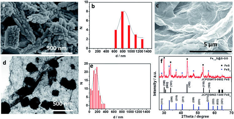
In our experiments, Fe1−xS@S-GO–NMC was prepared using a simple one-pot solvothermal approach, as shown in Fig. 1. The amounts of FeCl3 and TAA in solution were 0.003 and 0.045 mol. Meanwhile, Fe1−xS particles were prepared as a reference. Details of the synthesis process are reported in the experimental section. The SEM images shown in Fig. 2a illustrate that Fe1−xS agglomerated particles were seriously agglomerated. Fig. 2b shows that the agglomeration of Fe1−xS particles resulted in a non-uniform size (within the range of 500 nm to 2 microns) of the block or caking. The agglomerated Fe1−xS blocks or cakings cover many catalytically active sites on the surface of each Fe1−xS nanoparticle. In addition, the massive grain boundaries in the Fe1−xS blocks could possibly inhibit electron transport. These two factors may be the reason for the poor performance of previously reported devices based on pure FeS. We tried to inhibit the aggregation of Fe1−xS nanoparticles with GO. Fig. 2c shows the 2D structure of GO prepared using the modified Hummers' method.24 The surface of GO flakes up to ten microns is very smooth with only few wrinkles. In the case of a conductive film or a composite substrate, the large size of GO is beneficial to reducing the boundaries in the thin film and helps to limit the recombination of the electrons at the boundaries, and thus increases the conductivity. The TEM images of Fe1−xS@S-GO–NMC (Fig. 2d and e) show that Fe1−xS nanoparticles were dispersed on the GO surface. Fig. 2e shows the sizes of Fe1−xS nanoparticles dispersed on the RGO surface within the range of 40 nm to 350 nm. Thus, the GO effectively inhibits the aggregation of Fe1−xS nanoparticles. XRD patterns of Fe1−xS@S-GO–NMC (Fig. 2f) show that Fe1−xS@S-GO–NMC displays.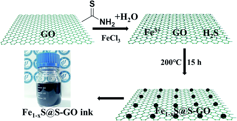 | ||
| Fig. 1 Schematic diagrams illustrating the simple one-pot hydrothermal approach for preparing Fe1−xS nanoparticles fixed on sulfur-doped graphene oxide (S-GO) sheets (namely, Fe1−xS@S-GO–NMC). | ||
FeS–FeS2 hybrid crystalline structure. Diffraction peaks at 30.0°, 30.8°, 33.8°, 43.6° and 53.3° were attributed to the (100), (002), (101), (102) and (110) planes, respectively, of the standard FeS nanocrystals with a hexagonal (P63/mmc) structure (JCPDS#75-0602). Diffraction peaks at 28.5°, 33.0°, 37.2°, 40.7°, 47.4° and 56.2° could be indexed to the (111), (200), (210), (211), (220) and (311) planes, respectively, of the standard FeS2 nanocrystals with a cubic [Pa-3(205)] structure (JCPDS#42-1340).
To further determine the structure and composition of Fe1−xS@S-GO–NMC, we conducted X-ray photoelectron spectroscopy (XPS) tests. The results are shown in Fig. 3. The full range of the XPS spectra of Fe1−xS@S-GO–NMC, S-GO and GO is shown in Fig. 3a. The mole ratio of FeCl3/TAA = 1/15, so the excess TAA will react with GO to form S-GO. The obvious peaks at 162.4 and 168.7 eV in the S 2p spectra of Fe1−xS@S-GO–NMC can be attributed to S in the FeS–FeS2 hybrid crystalline structure. In addition, shoulder peaks at 163.8 and 164.9 eV in the S 2p spectra of Fe1−xS@S-GO–NMC (as shown in Fig. 3b) can be observed. In order to assign shoulder peaks at 163.8 and 164.9 eV in the S 2p spectra of Fe1−xS@S-GO–NMC, we have synthesized S-GO with graphene oxide and TAA under the same experimental conditions as for Fe1−xS@S-GO–NMC. The obvious S 2p peaks at 163.8 and 164.9 eV can also be observed in the S 2p spectra of S-GO, as shown in Fig. 3b. Thus, shoulder peaks at 163.8 and 164.9 eV in the S 2p spectra of Fe1−xS@S-GO–NMC confirmed the formation of sulfur-doped graphene oxide in Fe1−xS@S-GO–NMC. A complex energy distribution of Fe 2p photoelectrons was obtained and is shown in Fig. 3c. The spectrum could be fitted using the “XPS peak” software with Gaussian functions after subtraction of a Shirley background. The Fe 2p spectrum could be fitted into four peaks which were associated with different Fe 2p in FeS and FeS2.26,27 The fitting data for different peaks are listed in Table 1. The main peaks at 712.1 and 725.4 eV were attributed to FeS 2p3/2 and 2p1/2. The peaks at 707.3 and 720.6 eV were attributed to FeS2 2p3/2 and 2p1/2. As can be seen from the areas in Table 1, FeS is the dominant component in the Fe1−xS@S-GO–NMC. The results are in agreement with the intensity of the XRD diffraction. Thus, the synthesis mechanism of Fe1−xS@S-GO–NMC can be described as follow:
| CH3CSNH2 + H2O → CH3COONH4 + H2S |
| FeCl3 + H2S → Fe1−xS + HCl + S |
| H2S + GO → S-GO |
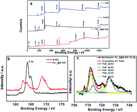 | ||
| Fig. 3 (a) Full-range XPS spectra of GO (blue), S-GO (black) and Fe1−xS@S-GO–NMC (red). (b) Comparison of S 2p for S-GO (black) and Fe1−xS@S-GO–NMC (red). (c) Fe 2p spectra of Fe1−xS@S-GO–NMC (red). | ||
| Peak | Position | Index | Area |
|---|---|---|---|
| Peak 1 | 707.3 | FeS2 2p3/2 | 1205 |
| Peak 2 | 712.1 | FeS 2p3/2 | 15003 |
| Peak 3 | 720.6 | FeS2 2p1/2 | 3808 |
| Peak 4 | 725.4 | FeS 2p1/2 | 17210 |
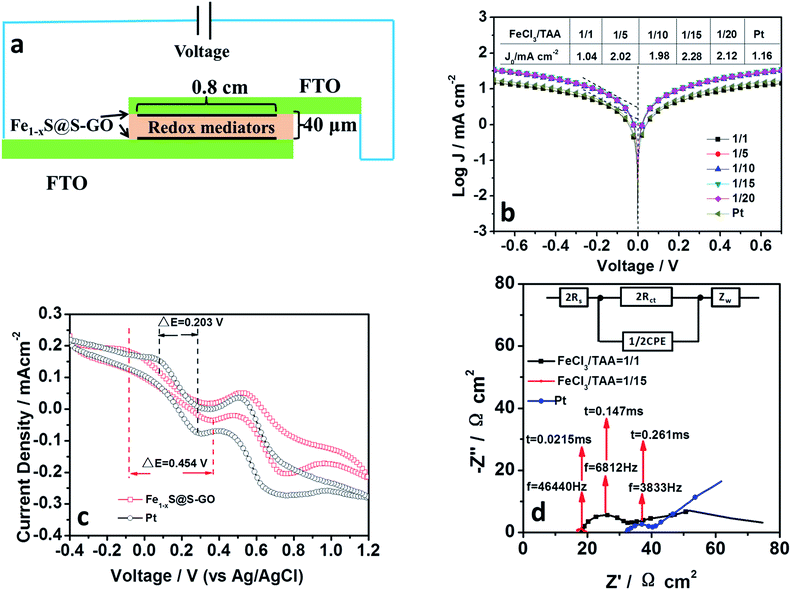
In order to demonstrate the hypothesis that an Fe1−xS@S-GO–NMC cathode has a good electrocatalytic performance, we investigated the electrocatalytic performance and the electron transfer of Fe1−xS@S-GO. Fe1−xS@S-GO ink was fabricated into a thin film electrode by spraying it onto a FTO/glass substrate. In our previous report, we optimized the catalyst loading in similar nano–micro composite catalysts (Fe3O4@RGO). For Fe3O4@RGO, a layer thickness of 16 μm is best. So we control the layer thickness of our cathode at 16 μm. Meanwhile, pyrolytic platinum was prepared for use as a cathode reference. Pyrolytic platinum was fabricated on FTO/glass by pyrolysis of a 0.16 wt% H2PtCl6 aqueous solution. The obtained film was sintered at 450 °C for 1 h. For EIS and Tafel characterizations, symmetrical cells were assembled using two identical cathodes filled with I3−/I− electrolytes and spaced by 40 μm tape, as shown in Fig. 4a. The active area of the symmetrical cell was 0.64 cm2. The exchange current density (J0) in the Tafel region (as shown in Fig. 4b) is very closely related to the kinetic rate of charge transfer between the reaction medium and the cathode. Tafel polarization curves of symmetrical cells fabricated with two identical cathodes (mole ratios of FeCl3/TAA = 1/1, 1/5, 1/10, 1/15, 1/20) are shown in Fig. 4b. J0 for the cathode material synthesized with a mole ratio of FeCl3/TAA = 1/1 was 1.04 mA cm−2, which is lower than that based on Pt (1.16 mA cm−2). When the mole ratio of FeCl3/TAA was increased to 1/5, 1/10, 1/15 and 1/20, the values of J0 also increased. The results indicated that the element of S-GO (formed by reaction between excess TAA and GO) in Fe1−xS@S-GO–NMC was beneficial for improving the kinetic rate of charge transfer between the reaction medium and the cathode. For Fe1−xS@S-GO–NMC synthesized with a mole ratio of FeCl3/TAA = 1/15, the J0 (2.28 mA cm−2) in the Tafel zone which resulted was remarkably higher than that of Pt (1.16 mA cm−2), indicating a faster electron exchange at the interface between the reaction medium and the cathode. The larger J0 well explains the high photovoltaic activity observed with the Fe1−xS@S-GO–NMC cathode. The Fe1−xS@S-GO–NMC cathode delivered a higher photocurrent density (13.0 ± 1.0 mA cm−2) compared to Pt (12.1 ± 0.6 mA cm−2), as shown in Table 2. Thus, the Fe1−xS@S-GO–NMC cathode allows for an accelerated electron transfer and for the regeneration of the redox mediator; this property in turn increases the solar-to-electrical conversion efficiency of the corresponding photovoltaic devices. Fig. 4c shows cyclic voltammograms of Fe1−xS@S-GO–NMC synthesized with a mole ratio of FeCl3/TAA = 1/15 and Pt for the I−/I3− redox couple. Curves obtained with the Fe1−xS@S-GO–NMC and a Pt cathode exhibited two pairs of redox peaks. The redox peak at low potential was ascribed to the reaction: I3− + 2e− → 3I−.25 The reduction potential and the oxidation potential obtained with Fe1−xS@S-GO–NMC were −0.085 V (vs. Ag/AgCl in saturated potassium chloride) and 0.369 V (vs. Ag/AgCl in saturated potassium chloride), respectively. The reduction potential and oxidation potential obtained under the same conditions with Pt were 0.078 V and 0.281 V. The separation between anodic and cathodic peaks (ΔE) is inversely proportional to the thermodynamic possibility of the above redox reaction. Interestingly, the ΔE value for Fe1−xS@S-GO–NMC (0.454 V) was higher than that for Pt (0.203 V), which may explain why the photovoltaic devices based on an Fe1−xS@S-GO–NMC cathode delivered a lower fill factor (0.72 ± 0.02) compared to the Pt cathode (0.78 ± 0.01), as shown in Table 2. EIS was carried out to reveal the inherent interface resistance, as shown in Fig. 4d. The arc at high frequency depends on the charge transfer resistance (Rct) at the interface between the cathode and the electrolyte. This parameter reflects the performance of the cathode material. The point of intersection between the plot at high frequency and the real axis of the Nyquist plot gives the series resistance (Rs). The values of the EIS parameters were obtained by fitting Nyquist plots with the Z-view software according to an equivalent circuit diagram (Fig. 4d, inset). The fitting results of the Nyquist plots are listed in Table 2. The Rct of symmetrical cells based on FeS@S-GO–NMC (synthesized with mole ratios of FeCl3/TAA = 1/1 and 1/15) and a Pt cathode were 16.17, 2.59 and 9.17 Ω cm2, respectively. The reciprocal of the highest frequency (f) of the top of the arc corresponds to the charge exchange resistance representing the reaction time constant (τ) of the reactant at the cathode surface. The smaller the time constant, the faster the reaction. The value (0.0215 ms) of τ obtained with the Fe1−xS@S-GO–NMC cathode (synthesized with a mole ratio of FeCl3/TAA = 1/15) was smaller than those obtained with Pt and Fe1−xS@GO–NMC (synthesized with a mole ratio of FeCl3/TAA = 1/1). Thus, the Fe1−xS@S-GO–NMC (synthesized with a mole ratio of FeCl3/TAA = 1/15) electrode exhibits a fast electron exchange process occurring at the interface between the reaction and the cathode. In addition, the ZN of symmetrical cells based on Fe1−xS@S-GO–NMC (synthesized with a mole ratio of FeCl3/TAA = 1/1) is 44.06 Ω cm2, which is smaller than that of a Pt cathode (132.80 Ω cm2). This indicates that the channels formed by 2D lamellar graphene are beneficial for the diffusion of the electrolyte, which makes the diffusion resistance (ZN) smaller. From the analysis of CV, Tafel and EIS results, we can see that the Fe1−xS@S-GO–NMC cathode exhibited excellent electrocatalytic performance, which in turn promoted the performance of the corresponding photovoltaic devices.
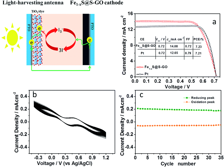
The photovoltaic performance was investigated by characterizing DSCs based on an Fe1−xS@S-GO (synthesized with a mole ratio of FeCl3/TAA = 1/15) cathode under AM 1.5, 100 mW cm−2 simulated illumination (schematic diagrams shown in Fig. 5). For each cathode, we fabricated four DSCs devices and determined the mean photovoltaic performance. The detailed photovoltaic parameters are summarized in Table 2. Fig. 5a shows the best photocurrent density with respect to voltage (J–V curve) for the DSCs in each group. The DSCs based on the Fe1−xS@S-GO–NMC cathode showed a solar-to-electrical conversion efficiency of 7.23% with an open circuit voltage (Voc) of 0.72 V, a short circuit current density (Jsc) of 14.08 mA cm−2 and a fill factor (FF) of 0.72. The conversion efficiency based on the Fe1−xS@S-GO–NMC cathode is nearly the same as that obtained from DSCs based on pyrolytic Pt cathodes (7.21%). Although the device is very similar to a tandem DSC, we did not find that the value of Voc in the device based on the Fe1−xS@S-GO–NMC cathode was significantly higher than from the one obtained with the reference Pt. Therefore, the excellent device performance obtained with the Fe1−xS@S-GO–NMC cathode is ascribed to the excellent electrocatalytic activity of the composite material, which could effectively recycle the redox mediator and reduce the over-potential. In addition, an investigation of the stability of Fe1−xS@S-GO–NMC in I3−/I− liquid electrolyte was carried out, as shown in Fig. 5b and c. The changes in the potentials and current density for the redox peaks in each cycle of the CV plots were not obvious. The results showed that the Fe1−xS@S-GO–NMC exhibited good stability in I3−/I− liquid electrolyte.
Conclusions
In conclusion, we synthesized a nano–micro composite composed of Fe1−xS nanoparticles decorated on sulfur-doped graphene oxide sheets by a one-step hydrothermal method. Compared to Fe1−xS agglomerated particles, GO sheets in NMC obviously prevented the aggregation of Fe1−xS nanoparticles. DSCs based on an Fe1−xS@S-GO–NMC cathode achieved the highest reported solar-to-electrical conversion efficiency up to 7.23% for photoelectrochemical cell. The superior performance of the photoelectrochemical device based on Fe1−xS@S-GO–NMC was attributed to the good electrocatalytic performance of the material. We hope that our work here will be of great interest for fundamental research and for practical applications of FeS or FeS2 and their composites in the solar splitting of water, artificial photoelectrochemical cells, and electrocatalytic applications.Conflicts of interest
There are no conflicts to declare.Acknowledgements
This work was financially supported by Shandong Province Natural Science Foundation (Grant No. ZR2016BQ20; BS2015NJ013; ZR2014BQ010; ZR2016BQ21), Colleges and universities in Shandong Province science and technology projects (Grant No. J16LC05), Science and Technology Innovation Foundation for the University or College Students (Grant No. 26312160502), National Science and Technology Innovation Foundation for the University or College Students (Grant No. 201510447021), Research Fund for the Doctoral Program of Liaocheng University (Grant No. 31805), National Natural Science Foundation of China (Grant No. 21503104; 21601078, 21401095), National Basic Research Program of China (Grant No. 2011CBA00701).Notes and references
- D. Tshala-Katumbay, J. C. Mwanza, D. S. Rohlman, G. Maestre and R. B. Oria, A global perspective on the influence of environmental exposures on the nervous system, Nature, 2015, 527, S187–S192 CrossRef CAS PubMed.
- J. Tollefson, Energy crisis upsets platinum market, Nature, 2008, 451, 877 CrossRef CAS PubMed.
- B. Obama, The irreversible momentum of clean energy, Science, 2017, 355, 126–129 CrossRef CAS PubMed.
- H. C. Jin, et al., Photothermal conversion efficiency of nanofluids: An experimental and numerical study, Sol. Energy, 2016, 139, 278–289 CrossRef CAS.
- A. Polman, M. Knight, E. C. Garnett, B. Ehrler and W. C. Sinke, Photovoltaic materials: Present efficiencies and future challenges, Science, 2016, 352, aad4424 CrossRef PubMed.
- N. S. Lewis, Developing a scalable artificial photosynthesis technology through nanomaterials by design, Nat. Nanotechnol., 2016, 11, 1010–1019 CrossRef CAS PubMed.
- Y. K. Chen, S. Hu, C. X. Xiang and N. S. Lewis, A sensitivity analysis to assess the relative importance of improvements in electrocatalysts, light absorbers, and system geometry on the efficiency of solar-fuels generators, Energy Environ. Sci., 2015, 8, 876–886 Search PubMed.
- H. Zhou, et al., Interlaced W18O49 nanofibers as a superior catalyst for the counter electrode of highly efficient dye-sensitized solar cells, J. Mater. Chem. A, 2014, 2, 4347–4354 CAS.
- J. Luo, et al., Water photolysis at 12.3% efficiency via perovskite photovoltaics and Earth-abundant catalysts, Science, 2014, 345, 1593–1596 CrossRef CAS PubMed.
- Y. Tachibana, L. Vayssieres and J. R. Durrant, Artificial photosynthesis for solar water-splitting, Nat. Photonics, 2012, 6, 511–518 CrossRef CAS.
- L. L. Quan, et al., A new in situ preparation method to FeS counter electrode for quantum dots-sensitized solar cells, J. Power Sources, 2014, 272, 546–553 CrossRef CAS.
- H. F. Geng, et al., Electrochemical Growth of FeS on Three-dimensional Carbon Scaffold as the High Catalytic and Stable Counter Electrode for Quantum Dot-sensitized Solar Cells, Electrochim. Acta, 2015, 182, 1093–1100 CrossRef CAS.
- H. F. Geng, et al., FeS/nickel foam as stable and efficient counter electrode material for quantum dot sensitized solar cells, J. Power Sources, 2015, 281, 204–210 CrossRef CAS.
- J. H. Huo, M. Zheng, Y. G. Tu and J. H. Wu, High-performance and transparent counter electrodes based on polypyrrole and ferrous sulfide nanoparticles for dye-sensitized solar cells, J. Mater. Sci.: Mater. Electron., 2016, 27, 5680–5685 CrossRef CAS.
- M. Batmunkh, et al., Sulfur-Doped Graphene with Iron Pyrite (FeS2) as an Efficient and Stable Electrocatalyst for the Iodine Reduction Reaction in Dye-Sensitized Solar Cells, Solar RRL, 2017, 1, 6 Search PubMed.
- L. Kavan, Exploiting Nanocarbons in Dye-Sensitized Solar Cells. Making and Exploiting Fullerenes, Graphene, and Carbon Nanotubes, Topics in Current Chemistry-Series, 2014, vol. 348, pp. 53–93 Search PubMed.
- L. Kavan, J. H. Yum and M. Graetzel, Graphene-based cathodes for liquid-junction dye sensitized solar cells: Electrocatalytic and mass transport effects, Electrochim. Acta, 2014, 128, 349–359 CrossRef CAS.
- M. Janani, P. Srikrishnarka, S. V. Nair and A. S. Nair, An in-depth review on the role of carbon nanostructures in dye-sensitized solar cells, J. Mater. Chem. A, 2015, 3, 17914–17938 CAS.
- L. Kavan, P. Liska, S. M. Zakeeruddin and M. Gratzel, Low-temperature Fabrication of Highly-Efficient, Optically-Transparent (FTO-free) Graphene Cathode for Co-Mediated Dye-Sensitized Solar Cells with Acetonitrile-free Electrolyte Solution, Electrochim. Acta, 2016, 195, 34–42 CrossRef CAS.
- L. Kavan, et al., Novel highly active Pt/graphene catalyst for cathodes of Cu(II/I)-mediated dye-sensitized solar cells, Electrochim. Acta, 2017, 251, 167–175 CrossRef CAS.
- J. Yin, et al., Indium- and Platinum-Free Counter Electrode for Green Mesoscopic Photovoltaics through Graphene Electrode and Graphene Composite Catalysts: Interfacial Compatibility, ACS Appl. Mater. Interfaces, 2016, 8, 5314–5319 CAS.
- L. Kavan, Electrochemistry and dye-sensitized solar cells, Current Opinion in Electrochemistry, 2017, 2, 88–96 CrossRef.
- K. Shehzad, Y. Xu, C. Gao and X. F. Duan, Three-dimensional macro-structures of two-dimensional nanomaterials, Chem. Soc. Rev., 2016, 45, 5541–5588 RSC.
- H. Zhou, et al., Earth-abundant and nano-micro composite catalysts of Fe3O4@reduced graphene oxide for green and economical mesoscopic photovoltaic devices with high efficiencies up to 9%, J. Mater. Chem. A, 2016, 4, 67–73 CAS.
- H. Zhou, et al., Printable fabrication of Pt-and-ITO free counter electrodes for completely flexible quasi-solid dye-sensitized solar cells, J. Mater. Chem. A, 2013, 1, 3932–3937 CAS.
- K. Laajalehto, I. Kartio and P. Nowak, XPS study of clean metal sulfide surfaces, Appl. Surf. Sci., 1994, 81, 11–15 CrossRef CAS.
- H. Binder, Investigations on nature of chemical bonds in iron-sulfur compounds using X-ray photoelectron spectroscopy, Z. Naturforsch., B: J. Chem. Sci., 1973, 28, 255–262 CAS.
| This journal is © The Royal Society of Chemistry 2018 |

