 Open Access Article
Materials with low dielectric constant and loss and good thermal properties prepared by introducing perfluorononenyl pendant groups onto poly(ether ether ketone)
Handong Sunab,
Yunxia Lvab,
Chongyang Zhangab,
Xiaodan Zuoab,
Mengzhu Liab,
Xigui Yue *ab and
Zhenhua Jiangab
aKey Laboratory of High Performance Polymers of the Ministry Education of China, College of Chemistry, Jilin University, 2699 Qianjin Street, Changchun 130012, People's Republic of China. E-mail: 35192993@qq.com
bNational Center of Quality Supervision and Inspection of Automobile Spare Parts, 6888 Nanhu Road, Changchun 130012, China. E-mail: yuexigui@jlu.edu.cn; Tel: +86-431-85168868
First published on 19th February 2018
Abstract
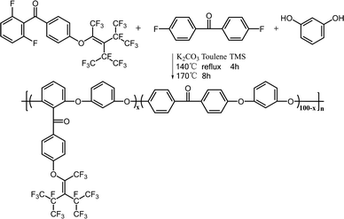
A new monomer, 2,6-difluorophenyl-(4′-perfluorononenyloxy)phenyl-methanone (2F-PFN), was synthesized using a simple two-step reaction. A series of novel poly(ether ether ketone)s (PEEK-PFN-x) containing perfluorononenyl groups were then prepared from 2F-PFN, resorcin, and 4,4′-difluorobenzophenone by nucleophilic polycondensation. The resulting copolymers were found to have different electric and thermal properties depending on the molar ratio of perfluorononenyl groups. PEEK containing a 5% molar ratio of perfluorononenyl (PEEK-PFN-5) possessed an intrinsic low dielectric constant of 2.73 and low dielectric loss of 3.00 × 10⁻³ at 10 kHz. Another blended polymer prepared from PEEK and PTFE (PEEK/PTFE-5) possessed a dielectric constant of 3.21 and dielectric loss of 6.00 × 10⁻³ at 10 kHz. Therefore, PEEK/PTFE-5 had much higher dielectric loss than that of PEEK-PFN-5 with the same fluorine content. PEEK-PFN-5 also showed excellent thermal stability, with a 5 wt%-loss temperature of 436 °C. PEEK-PFN-5 showed a slight increase in hydrophobicity, with a water droplet contact angle of 89.7° compared with that of PEEK/PTFE-5 (86.4°) containing the same fluorine content as PEEK-PFN-5. Morphologies and fluoride distribution on the membrane surfaces were characterized by field emission SEM equipped with EDX. These results indicated that PEEK-PFN-5 possessed a more uniform distribution of fluorine on the membrane top surface than PEEK-PTFE-5.
Introduction
In the last few decades, improvements in the performance of microelectronic integrated circuits (ICs) have focused on increasing transistor speed, reducing transistor size, and packing more transistors onto a single chip.1 There is an urgent need for high-performance polymers with low dielectric constant that possess low dielectric loss to overcome signal delays, power dissipation, and line-to-line crosstalk noise between the metal interconnections within integrated circuits.2 Organic polymer dielectric materials display low dielectric constant and low dielectric loss, but have additional problems that must be addressed their use in microelectronic devices. For example, hydrophobicity and solubility are important properties.3,4 In particular, when a large surface area of material is exposed to air for a long time during processing, its dielectric properties will be affected by the air humidity.5 Water has extremely polar O–H bonds and a dielectric constant of around 80. A small amount of absorbed water will distinctly increase the dielectric constant.6 Increasingly small gaps between the metal lines in ICs require the materials to be deposited using an appropriate method, such as spin coating of a polymer solution.1 This method requires polymers to be soluble in most organic solvents. Therefore, high performance polymers that possess good hydrophobicity have received much attention in microelectronic devices.7–12Poly(ether ether ketone) (PEEK) is a high performance thermal plastic widely used in many fields, including aerospace, electronics, and nuclear industries, due to its excellent mechanical and thermo-oxidative stability, and chemical and weather resistance.13–16 PEEK is expected to be used in microelectronic devices, including as a substrate for printed wire boards, an insulating material for interlayer dielectrics and intermetal dielectrics, and a coating in electronic packaging.17–23 However, PEEK is difficult to use in thin films and coatings owing to its low solubility in most known solvents, except for concentrated sulfuric acid, due to its semicrystalline texture structure and the molecular rigidity of its repeating units, which contain both ether and ketone linkages in the polymer chain.24–27 Furthermore, high-performance PEEKs with both low dielectric constants and low dielectric loss are scarce among those investigated so far.
According to the Debye equation, there are two main ways to decrease the dielectric constant of polymers. The first is to incorporate highly symmetric low polar groups to decrease molar polarizability.28,29 The second is to introduce bulky pendant groups into the molecular structure to increase the distances between molecular chains.11,12,25,30–32 To prepare PEEKs with low dielectric constants using these two routes, considerable work has focused on introducing flexible linkages, highly fluorinated symmetrical units, or fluorinated bulky pendant groups into the polymer backbone. The latter approach is used because fluorine is the most electronegative element (4.0) and about the same size as hydrogen. Furthermore, carbon–fluorine bonds are relatively short, with a high bond energy (489 kJ mol−1) and polarity. These fluorine-containing PEEKs generally show greater flame resistance, lower dielectric constants, and improved hydrophobicity compared with their nonfluorinated analogues. Among this research, introducing fluorinated substituents by replacing hydrogen on aromatic rings with fluorine has been considered a promising method because per-fluorinated aromatic structures are highly symmetrical structure and C–F bonds are resistant to polarization. Therefore, introducing perfluorinated aromatic structures tends to achieve a lower dielectric constant without increasing the dipole moment and dielectric constant. PEEK derived from hexafluorobenzene and decafluorobiphenyl were synthesized by Irvin et al.33 These polymer materials had a much lower dielectric constant of 2.17 compared with that of PEEK. A PEEK derivative based on decafluorobiphenyl and (4-chloro-3-trifluoromethyl) phenylhydroquinone with a dielectric constant of 2.71 was prepared by Liu et al.34 However, the dielectric loss values of these fluorinated polymers were not mentioned.
Strategies for introducing bulky pendant groups have also been shown to improve the solubility and dielectric properties of the polymers. Liu's group reported the synthesis of new fluorine-containing PEEKs with trifluoromethylphenyl and (3,5-difluoromethyl)phenyl moieties and dielectric constants of 2.70 and 2.69 at 10 kHz for 3F-PEEK and 6F-PEEK.27 The polymer solubility was also improved compared with that of PEEK. Although this method has been shown to improve the dielectric constant of the polymers, the low dielectric loss and hydrophobicity were not mentioned in these studies.
In this work, novel fluorinated copolymers (PEEK-PFN-x), with low dielectric constants, low dielectric loss, good hydrophobicity, and good thermal properties, were designed and synthesized by condensation co-polymerization for potential applications in electronic device. To show that uniform distribution of fluorine elements can lead to better hydrophobic performance, the surface morphologies and element distributions of the polymer membranes were identified by FESEM equipped with EDX.
Experimental
Materials
4,4′-Difluorobenzophenone, resorcin, and phenol were purchased from Aladdin Reagent Co. Ltd. and used after recrystallization. Anhydrous potassium carbonate was purchased from Beijing Chemical Reagents and ground and dried at 150 °C in an oven before use. Triethylamine, methoxybenzene, and 48% HBr were supplied by Energy Chemical and used as received. Tetramethylene sulfone and N,N-dimethylformamide were purified by distillation under reduced pressure. Other chemicals were supplied by Beijing Chemical Reagent or Tianjin Chemical Reagent, and used without further purification.Measurement
NMR spectra were recorded on a Varian mercury (300 MHz) spectrometer using tetramethylsilane as reference. Thermogravimetric analysis (TGA) was performed under a nitrogen atmosphere at a heating rate of 10°C min−1 on polymers in open aluminum pans using a Pyris 1 TGA instrument (PerkinElmer). Before analysis, the TGA furnace temperature was kept at 100 °C under a nitrogen atmosphere for 10 min to remove water. Differential scanning calorimetry (DSC) was performed on a TA Q2000 instrument at a heating rate of 10°C min−1 in the range 100–200 °C under nitrogen. Scanning electron microscopy (SEM) images of the membranes were obtained using an FEI Nova Nano 450 microscope. Contact angles (CAs) of the prepared membranes were measured using a contact goniometer (POWEREACH/JC2002C2 CA meter). Before testing, the membranes were vacuum dried for 12 h. Dielectric constants of the thin membranes (coated with silver using a vacuum evaporation method) were obtained using a Hewlett-Packard 4285A apparatus at room temperature using a frequency range of 1000 Hz to 10 MHz.Synthesis of (2,6-difluorophenyl)(4′-methoxyphenyl)methanone (2F-MM)
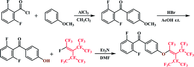
Methoxybenzene (2.2707 g, 21 mmol), AlCl3 (3.0666 g, 23 mmol), and CH2Cl2 (10 mL) were mixed in a 100 mL three-necked round-bottom flask in an ice bath under a nitrogen atmosphere. A solution of 2,6-difluorobenzoyl chloride (2.2709 g, 21 mmol) in dichloroethane (5 mL) was slowly added dropwise to the reaction mixture with stirring. The reaction mixture was then stirred for 8 h at room temperature and monitored by thin-layer chromatography (petroleum ether/dichloromethane = 3![[thin space (1/6-em)]](https://www.rsc.org/images/entities/char_2009.gif) :
:![[thin space (1/6-em)]](https://www.rsc.org/images/entities/char_2009.gif) 1). 5% HCl (10 mL) was then added slowly to the reaction mixture and stirring continued for another 8 h. The reaction mixture was poured into distilled water (250 mL) and extracted with dichloromethane (10 mL × 3). The organic layer was collected and evaporated. Pure product was obtained after recrystallization from alcohol/H2O (1
1). 5% HCl (10 mL) was then added slowly to the reaction mixture and stirring continued for another 8 h. The reaction mixture was poured into distilled water (250 mL) and extracted with dichloromethane (10 mL × 3). The organic layer was collected and evaporated. Pure product was obtained after recrystallization from alcohol/H2O (1![[thin space (1/6-em)]](https://www.rsc.org/images/entities/char_2009.gif) :
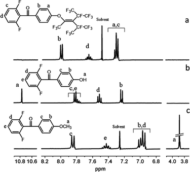
:![[thin space (1/6-em)]](https://www.rsc.org/images/entities/char_2009.gif) 2). (Yield: 69%) 1H NMR (CDCl3, ppm): δ 3.88 (s, 3H, Ha), 6.94–6.97 (d, 2H, Hb, J = 8.95 Hz), 7.83–7.86 (d, 2H, Hc, J = 8.93 Hz), 6.99–7.02 (m, 2H, Hd), 7.34–7.47 (m, 1H, He).
2). (Yield: 69%) 1H NMR (CDCl3, ppm): δ 3.88 (s, 3H, Ha), 6.94–6.97 (d, 2H, Hb, J = 8.95 Hz), 7.83–7.86 (d, 2H, Hc, J = 8.93 Hz), 6.99–7.02 (m, 2H, Hd), 7.34–7.47 (m, 1H, He).
Synthesis of (2,6-difluorophenyl)(4′-hydroxyphenyl)methanone (2F-HPM)
A mixture of 2F-MM (3.004 g, 12.1 mmol), glacial acetic acid (25 mL), and 48% HBr (15 mL) was heated at reflux for 8 h. The reaction mixture was then poured into ice water (100 mL) and the crude product was filtered and purified by recrystallization from alcohol to afford (2,6-difluorophenyl)(4′-hydroxyphenyl)methanone as a white solid. (Yield: 85%) 1H NMR (DMSO-d6, ppm): δ 10.77 (s, 1H, Ha), 6.90–6.93 (d, 2H, Hb, J = 8.97 Hz), 7.67–7.70 (d, 2H, Hc, J = 8.78 Hz), 7.25–7.30 (t, 2H, Hd, J = 8.38 Hz), 7.59–7.65 (m, 1H, He).Synthesis of 2F-PFN
2F-HPM (9.3680 g, 40 mmol), triethylamine (4.0476 g, 40 mmol), and DMF (40 mL) were mixed in three-necked round-bottom flask under a nitrogen atmosphere. After slowly increasing the reaction temperature to 70 °C, perfluorononene (2.1603 g, 48 mmol) was added dropwise within 1.5 h. The reaction was continued for 3.5 h after perfluorononene addition was complete and monitored by TLC (petroleum ether/dichloromethane = 4![[thin space (1/6-em)]](https://www.rsc.org/images/entities/char_2009.gif) :
:![[thin space (1/6-em)]](https://www.rsc.org/images/entities/char_2009.gif) 1). The resulting mixture was purified by reduced pressure distillation to remove the solvent. The obtained oily mixture was poured into 5% HCl (200 mL) and the solution was extracted with dichloromethane (10 mL × 3). The organic layer was then dried over anhydrous Na2SO4 and concentrated on a rotary evaporator under reduced pressure. The residue was purified by silica gel column chromatography (CH2Cl2/petroleum ether = 1
1). The resulting mixture was purified by reduced pressure distillation to remove the solvent. The obtained oily mixture was poured into 5% HCl (200 mL) and the solution was extracted with dichloromethane (10 mL × 3). The organic layer was then dried over anhydrous Na2SO4 and concentrated on a rotary evaporator under reduced pressure. The residue was purified by silica gel column chromatography (CH2Cl2/petroleum ether = 1![[thin space (1/6-em)]](https://www.rsc.org/images/entities/char_2009.gif) :
:![[thin space (1/6-em)]](https://www.rsc.org/images/entities/char_2009.gif) 5) to afford the desired products. (Yield: 72%) 1H NMR (CDCl3, ppm): δ 6.06–6.99 (m, 4H, Ha Hc), 7.92–7.94 (d, 2H, Hb, J = 8.87 Hz), 7.43–7.53 (m, 1H, Hd) (Scheme 1).
5) to afford the desired products. (Yield: 72%) 1H NMR (CDCl3, ppm): δ 6.06–6.99 (m, 4H, Ha Hc), 7.92–7.94 (d, 2H, Hb, J = 8.87 Hz), 7.43–7.53 (m, 1H, Hd) (Scheme 1).
Synthesis of PEEK-PFN-x
As shown in Scheme 2, PEEKs with perfluorononenyl side groups (PEEK-PFN-x) were obtained via a typical polycondensation protocol, as illustrated by the preparation of PEEK-PFN-5 copolymer, where 5 represents the molar percentage of novel monomer in the total difluoride monomer. In a 25 mL three-necked round-bottom flask equipped with a mechanical stirrer, Dean-Stark trap, condenser, nitrogen inlet, and thermometer, was placed 2F-PNE (0.3321 g, 0.5 mmol), 4,4′-difluorobenzophenone (2.0829 g, 9.5 mmol), resorcinol (1.1011 g 10 mmol), potassium carbonate (1.6584 g, 12 mmol), sulfolane (20 mL), and toluene (15 mL). Under a nitrogen atmosphere, the solution was heated to 120 °C with stirring and maintained at that temperature for 4 h. After the produced water was removed by azeotropic distillation with toluene, the mixture was heated to 175 °C for about 8 h until a highly viscous solution was obtained. The mixture was then rapidly poured into deionized water to precipitate the polymer. The polymer was isolated by filtration and washed several times with water. The polymer was dried under vacuum at 60 °C for 12 h to afford PEEK-PFN-5. For polymers denoted as PEEK-PFN-x, x represents the molar percentage of 2F-PFN.Membrane preparation
PEEK-PFN-x membranes were prepared by casting 10 wt% polymer in DMF onto glass plates. After drying at 120 °C for 12 h, a tough membrane was obtained. Two blended membranes of PEEK and PTFE (PEEK/PTFE-x) were prepared by solution blending of PEEK with different amounts of PTFE powder under ultrasonic dispersion. The amounts of PTFE used in the blended polymers were the same as those of the perfluorononenyl groups in PEEK-PFN-x.Results and discussion
Structural analysis
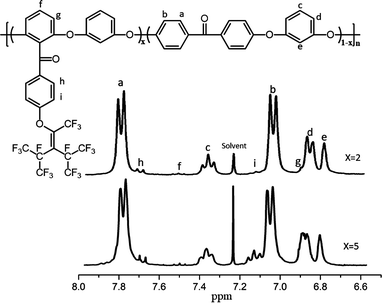
Two aromatic fluorinated PEEKs (PEEK-PFN-x) were synthesized via nucleophilic aromatic substitution. The chemical structures of the polymers were confirmed by NMR (CDCl3) (Fig. 1). In the 1H NMR spectra, the chemical shifts and assignments were consistent with the expected structure of PEEK-PFN-x. Signals in the range 6.8–7.9 ppm were attributed to aromatic protons in the polymer backbone. Doublet peaks in the range 7.7–7.8 ppm were assigned to protons ortho to carbonyl groups. Two hydrogen atoms were present in the ortho position of Hc, with a triplet observed at 7.36–7.41 ppm. Owing to the presence of ortho hydrogen atoms, the signal for Hd was split into two peaks at 7.1 ppm. A singlet peak was also observed at 6.83 ppm which was assigned to He. Multiplet peaks at 7.8–7.5 ppm were assigned to Hf. The peaks at 6.9 ppm, 7.7 ppm, and 7.1 ppm corresponded to Hg, Hh, and Hi, respectively (Fig. 2).Thermal properties of PEEK-PFN-x
Good thermal properties are a necessary requirement for polymers for effective application in dielectric devices. Owing to the fully aromatic backbone structure of PEEK-PFN-x, the resulting polymers showed outstanding heat resistance, as shown in Fig. 3a. Degradation began with the weakest perfluorinated carbon chain breaking. Obvious degradation was observed at 425–600 °C due to the degradation of fluorine-containing side chains. The second stage of weight loss beginning at 600 °C was attributed to decomposition of the polymer main chain. PEEK-PFN-x exhibited two-stage thermal decomposition profiles in nitrogen. This distinct two-stage thermal degradation also indicated the presence of the perfluorononenyl side group. The 5%-weight-loss temperatures (Td5) of PEEK-PFN-2 and PEEK-PFN-5 in nitrogen were 579 °C and 436 °C, respectively. This difference was caused by the increasing amount of perfluorinated carbon chains in the polymers. The corresponding char yields at 800 °C in nitrogen were 52 and 58 wt%, respectively. The TGA results demonstrated that PEEK-PFN-x possessed fairly high thermal stability. The introduction of perfluorinated carbon side chains produced internal plasticization via flexible pendant groups. This resulted in an increase in free volume, which led to decreased glass transition temperatures for PEEK-PFN-x (Fig. 3b). Compared with the glass transition of PEEK-PFN-2 (Tg = 126 °C), the Tg of PEEK-PFN-5, which contained more fluorocarbon chains, was much lower, at 97 °C.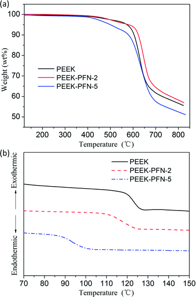 | ||
| Fig. 3 (a) TGA curves of PEEK and PEEK-PFN-x; (b) DSC curves of PEEK and PEEK-PFN-x: Tg(PEEK) = 136.3 °C, Tg(PEEK-PFN-2) = 124.1 °C, Tg(PEEK-PFN-5) = 96.2 °C. | ||
Surface morphology and hydrophobicity of PEEK-PFN-x membranes
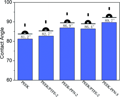
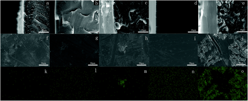
The hydrophobicity of membranes was evaluated using the static contact angle. The static water contact angles of conventional PEEK and modified PEEK/PTFE-x membranes with different fluoride contents were measured by a contact goniometer and are shown in Fig. 4. The measurement was started after 5 s of connection between water droplets and the membrane surface. Three points on each membrane were tested and averages of the measured values were reported.The absence of perfluorononenyl side groups in the PEEK-PFN-x chains resulted in a slightly improved hydrophobicity and a contact angle of about 81.2°. However, the hydrophobicity of PEEK-PFN-x membranes improved as the amount of fluorocarbon chain increased. Therefore, fluorine addition to the aromatic main chain structure had a distinct effect upon the hydrophobicity. The incorporation of fluorine atoms into the polymer chains led to increased hydrophobicity, resulting in an increased contact angle. Initially, the introduction of fluorine into polymers improved the hydrophobic performance. As shown in Fig. 4, the contact angle of PEEK-PFN-2 was higher than that of PEEK, which indicated that the hydrophobicity of PEEK-PFN-2 was stronger than that of PEEK. Furthermore, an increasing amount of fluorine afforded increased hydrophobic properties. The distributions of fluorine on the PEEK-PFN-x surface were obtained using SEM equipped with an EDX detector. Mappings showed the surface of PEEK-PFN-5 and PEEK-PFN-2 membranes, and showed the uniform distribution of fluoride. Based on the reactions shown in Scheme 2, the amount of fluorine in the polymer membranes was affected by the 2F-PFN content. Furthermore, the contact angle values of PEEK-PFN-5 were higher than those of PEEK-PFN-2, which were attributed to the increasing amount of fluorocarbon groups grafted on the main chain. We also observed a higher fluoride content on the top surface of PEEK-PFN-5 compared with that of PEEK-PFN-2. The fluorine mapping of membranes and their contact angles showed that introduced fluorine into the membranes could enhance the hydrophobicity. PTFE has been shown to have excellent hydrophobic properties, with the incorporation of PTFE into materials able to improve the hydrophobicity. The blended polymer of PEEK and PTFE powder was prepared by ultrasonic dispersion and then casting the solution into films. Static water contact angles of membranes mixed with different contents of PTFE are shown in Fig. 4. The incorporation of hydrophobic PTFE powder into the membrane doped solution was supposed to enhance the hydrophobicity of the prepared membranes. EDX mapping was used to analyze the distribution of elements on the membrane top surface.
SEM images of cross-sections are shown in Fig. 5(a)–(e). According to the SEM images, the prepared PEEK/PTFE-x blends were asymmetric, with PTFE powder concentrated in the surface layer. Furthermore, the top surface of these membranes contained a nonuniform distribution of fluoride. The influence of an increasing amount of PTFE in the PEEK/PTFE-x on hydrophobicity was similar to that observed for increasing fluorine density on the membrane surface. However, PTFE powder had a limited effect on the hydrophobicity of the membranes. Using the same amount of fluorine, the chemical grafting method promoted hydrophobicity more effectively than the hybrid approach. This was because the membrane hydrophobicity using the hybrid approach was dependent on the concentration of PTFE powder at the top surface. However, owing to the higher surface energy of PTFE, agglomeration easily occurred during preparation of the PEEK/PTFE-x membranes. Therefore, membranes prepared by the chemical grafting method showed better hydrophobicity than those prepared by the hybrid approach.
Dielectric properties
The dielectric properties of the membranes were measured at frequencies ranging from 1000 Hz to 10 MHz at 20 °C and 50% relative humidity. The dielectric constant of the PEEK membrane was also measured for comparison, as shown in Fig. 5. PEEK-PFN-2 and PEEK-PFN-5 had dielectric constants of 3.20 and 2.74 at 10 kHz, respectively, which were much lower than that of PEEK film (3.47). In general, dielectric constants of materials usually decrease with increasing frequency. However, PEEK-PFN-x membranes showed good dielectric constant stability with changing frequency. With increasing frequency, the dielectric constants of PEEK-PFN-x remained consistent.The values of dielectric constants corresponding to molecular polarization characteristics were determined using the Debye equation:
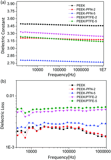 | ||
| Fig. 6 Dependence of (a) dielectric constant and (b) dielectric loss on frequency for PEEK, PEEK-PFN-x, and PEEK/PTFE-x at room temperature. | ||
| PEEK | PEEK-PFN-2 | PEEK/PTFE-2 | PEEK-PFN-5 | PEEK/PTFE-5 | |
|---|---|---|---|---|---|
| Dielectric constant | 3.47 | 3.20 | 3.28 | 2.74 | 3.21 |
| Dielectric loss | 2.40 × 10⁻³ | 2.50 × 10⁻³ | 5.32 × 10⁻³ | 3.00 × 10⁻³ | 5.98 × 10⁻³ |
| Tg (°C) | 136.3 | 124.1 | — | 92.2 | — |
| Td2 (°C) | 471.8 | 480.4 | — | 365.9 | — |
| Td5 (°C) | 573.5 | 580.3 | — | 436.3 | — |
The results in Fig. 6b show that PEEK-PFN-x membranes possessed a much lower dielectric loss than PEEK/PTFE-x membranes. This could be caused by conductance loss or polarization loss. Polarization loss arises when the dielectric material is under the electric field. However, a certain amount of time was required to establish polarization. When the dielectric polarization rate lagged behind the electric field, materials overcame internal resistance and generated power loss. Enhanced dielectric properties of the polymers were achieved with the incorporation of perfluorononenyl side chains, without compromising performance in other aspects, such as the stability of dielectric properties and dielectric loss (Table 2).
| DMF | DMAc | NMP | DMSO | THF | CHCl3 | |
|---|---|---|---|---|---|---|
| a Solubility under a mass of liquid: 0.1 g mL−1.b ++, soluble at room temperature; −, insoluble even on heating; NMP, N-methyl-2-pyrrolidone; DMAc, N,N-dimethylacetamide; DMF, N,N-dimethylformamide; DMSO, dimethylsulfoxide; THF, tetrahydrofuran; CHCl3, chloroform. | ||||||
| PEEK-PFN-2 | ++ | ++ | ++ | + | − | ++ |
| PEEK-PFN-5 | + | + | ++ | + | − | ++ |
Conclusions
A new difluoride monomer, 2F-PFN, was synthesized and introduced into a polymer molecular chain as a bulk pendant group by condensation copolymerization from resorcin and 4,4′-difluorobenzophenone. By incorporating 2F-PFN and controlling the chemical and repeat unit structure of the polymer at the molecular level, PEEK-PFN-x polymers were obtained with outstanding low-k and enhanced hydrophobicity. As PEEK-PFN-x contained a more uniform distribution of fluorine, it possessed better hydrophobicity than PEEK/PTFE-x. PEEK-PFN-x showed a significantly improved dielectric constant compared with that of PEEK/PTFE-x with the same fluorine content. Unlike the blended membrane, for which the dielectric loss was 5.98 × 10⁻³ at 10 kHz, the dielectric loss of PEEK-PFN-x was as low as 3.00 × 10⁻³ at 10 kHz. This provided new insight into the development of functional materials with low dielectric constants and enhanced hydrophobicity. The excellent collective properties of PEEK-PFN-x, including dielectric properties, high thermal stability, high hydrophobicity, and good solubility, make it a promising candidate for use in electric fields.Conflicts of interest
There are no conflicts to declare.Acknowledgements
This work was financially supported by the Science and Technology Department of Jilin Province Foundation (No. 20160203006GX and 20170203008GX). The authors also thank Lifeng Wang and Yan Wang from the Alan G. MacDiarmid Institute for their kind help with structural characterization.References
- D. Shamiryan, T. Abell, F. Iacopi and K. Maex, Mater. Today, 2004, 7, 34–39 CrossRef CAS.
- Y. Liu, Y. Zhang, Q. Lan, S. Liu, Z. Qin, L. Chen, C. Zhao, Z. Chi, J. Xu and J. Economy, Chem. Mater., 2012, 24, 1212–1222 CrossRef CAS.
- W. Volksen, R. D. Miller and G. Dubois, Chem. Rev., 2010, 110, 56–110 CrossRef CAS PubMed.
- M. Morgen, E. T. Ryan, J. H. Zhao, C. Hu, T. H. Cho and P. S. Ho, Annu. Rev. Mater. Sci., 2000, 30, 645–680 CrossRef CAS.
- G. Maier, Prog. Polym. Sci., 2001, 26, 3–65 CrossRef CAS.
- J. M. Hao, Y. F. Wei and J. X. Mu, RSC Adv., 2016, 6, 87433–87439 RSC.
- R. Q. Na, P. F. Huo, X. R. Zhang, S. L. Zhang, Y. L. Du, K. Zhu, Y. N. Lu, M. H. Zhang, J. S. Luan and G. B. Wang, RSC Adv., 2016, 6, 65186–65195 RSC.
- Y. N. Lu, S. L. Zhang, Z. Geng, Y. L. Du, K. Zhu, Y. G. Li and G. B. Wang, RSC Adv., 2016, 6, 72999–73005 RSC.
- B. Dong, Y. Wang, J. H. Pang, S. W. Guan and Z. H. Jiang, RSC Adv., 2015, 5, 107982–107991 RSC.
- W. Wei, H. Zhang, S. Guan, Z. Jiang and X. Yue, Polymer, 2012, 53, 5002–5009 CrossRef CAS.
- W. Chen, Z. Zhou, T. Yang, R. Bei, Y. Zhang, S. Liu, Z. Chi, X. Chen and J. Xu, React. Funct. Polym., 2016, 108, 71–77 CrossRef CAS.
- Y. Liu, Y. Zhang, Q. Lan, Z. Qin, S. Liu, C. Zhao, Z. Chi and J. Xu, J. Polym. Sci., Part A: Polym. Chem., 2013, 51, 1302–1314 CrossRef CAS.
- Q. H. Wang, F. Zheng and T. M. Wang, Cryogenics, 2016, 75, 19–25 CrossRef CAS.
- L. Major, J. M. Lackner, M. Kot and B. Major, Tribol. Int., 2016, 104, 309–320 CrossRef CAS.
- H. J. Song, Z. Z. Zhang and X. H. Men, Appl. Phys. A: Mater. Sci. Process., 2008, 91, 73–76 CrossRef CAS.
- D. L. Burris and W. G. Sawyer, Wear, 2006, 261, 410–418 CrossRef CAS.
- S. Yang, Y. Ahn and D. Kim, J. Mater. Chem. A, 2017, 5, 2261–2270 CAS.
- J. C. Liu, P. L. Zheng, M. N. Feng and X. B. Liu, Ionics, 2017, 23, 671–679 CrossRef CAS.
- B. L. Wang, L. H. Hong, Y. F. Li, L. Zhao, Y. X. Wei, C. J. Zhao and H. Na, ACS Appl. Mater. Interfaces, 2016, 8, 24079–24088 CAS.
- K. J. Smith, I. D. H. Towle, J. F. Pratte, R. K. Maskell and M. G. Moloney, Eur. Polym. J., 2016, 84, 538–549 CrossRef CAS.
- R. Q. Na, G. Z. Huo, S. L. Zhang, P. F. Huo, Y. L. Du, J. S. Luan, K. Zhu and G. B. Wang, J. Mater. Chem. A, 2016, 4, 18116–18127 CAS.
- L. M. Lin, Z. Chen, Z. P. Zhang, S. N. Feng, B. Liu, H. B. Zhang, J. H. Pang and Z. H. Jiang, Polymer, 2016, 96, 188–197 CrossRef CAS.
- J. A. Feng, Y. W. Xu, Y. Sun, S. Y. Wen, Y. L. Lei, L. Zhang and J. C. Huo, J. Polym. Res., 2016, 23, 7 CrossRef.
- Y. Zhang, X. Sun, R. Xu, Y. Niu, G. Wang and Z. Jiang, Mater. Chem. Phys., 2006, 99, 465–469 CrossRef CAS.
- Y. Niu, X. Zhu, L. Liu, Y. Zhang, G. Wang and Z. Jiang, React. Funct. Polym., 2006, 66, 559–566 CrossRef CAS.
- X. Ma, B. Liu, D. Wang, G. Wang, S. Guan and Z. Jiang, Mater. Lett., 2006, 60, 1369–1373 CrossRef CAS.
- W. Hu, C. Chen, Z. Jiang, W. Zhang and B. Liu, Polym. Adv. Technol., 2003, 14, 221–225 CrossRef.
- K. Kimura, Y. Tabuchi, A. Nishichi, Y. Yamashita, Y. Okumura and Y. Sakaguchi, Polym. J., 2001, 33, 290–296 CrossRef CAS.
- K. Kimura, Y. Tabuchi, Y. Yamashita, P. E. Cassidy, J. W. Fitch and Y. Okumura, Polym. Adv. Technol., 2000, 11, 757–765 CrossRef CAS.
- A. S. More, S. K. Pasale, P. N. Honkhambe and P. P. Wadgaonkar, J. Appl. Polym. Sci., 2011, 121, 3689–3695 CrossRef CAS.
- X. Li, X. L. Liu, L. J. Cheng, J. W. Jiang and S. R. Sheng, J. Fluorine Chem., 2014, 157, 30–34 CrossRef CAS.
- A. Fortney and E. Fossum, Polymer, 2012, 53, 2327–2333 CrossRef CAS.
- J. A. Irvin, C. J. Neef, P. E. Cassidy and K. M. Kane, J. Polym. Sci., Part A: Polym. Chem., 1992, 30, 1675–1679 CrossRef CAS.
- B. Liu, W. Hu, Y. Jin, C. Chen, Z. Jiang, Z. Wu, T. Matsumoto and A. Matsumura, Macromol. Chem. Phys., 2004, 205, 1677–1683 CrossRef CAS.
| This journal is © The Royal Society of Chemistry 2018 |

