 Open Access Article
Performance optimization of freestanding MWCNT-LiFePO4 sheets as cathodes for improved specific capacity of lithium-ion batteries†
Rahmat Agung Susantyoko a,
Tawaddod Saif Alkindia,
Amarsingh Bhabu Kanagaraja,
Boohyun Ana,
Hamda Alshiblia,
Daniel Choia,
Sultan AlDahmanib,
Hamed Fadaqb and
Saif Almheiri
 *ac
*ac
aDepartment of Mechanical Engineering, Khalifa University of Science and Technology, Masdar Institute, Masdar City, P. O. Box 54224, Abu Dhabi, United Arab Emirates. E-mail: saif.almheiri@ku.ac.ae; salmheiri@masdar.ac.ae
bUnited Arab Emirates Space Agency, Space Missions' Science and Technology Directorate, P. O. Box: 7133, Abu Dhabi, United Arab Emirates
cDivision of Engineering Technology and Science, Higher Colleges of Technology, United Arab Emirates
First published on 4th May 2018
Abstract
The typical lithium-ion-battery positive electrode of “lithium-iron phosphate (LiFePO4) on aluminum foil” contains a relatively large amount of inactive materials of 29 wt% (22 wt% aluminum foil + 7 wt% polymeric binder and graphitic conductor) which limits its maximum specific capacity to 120.7 mA h g−1 (71 wt% LiFePO4) instead of 170 mA h g−1 (100 wt% LiFePO4). We replaced the aluminum current-collector with a multi-walled carbon nanotube (MWCNT) network. We optimized the specific capacity of the “freestanding MWCNT-LiFePO4” positive electrode. Through the optimization of our unique surface-engineered tape-cast fabrication method, we demonstrated the amount of LiFePO4 active materials can be as high as 90 wt% with a small amount of inactive material of 10 wt% MWCNTs. This translated to a maximum specific capacity of 153 mA h g−1 instead of 120.7 mA h g−1, which is a significant 26.7% gain in specific capacity compared to conventional cathode design. Experimental data of the freestanding MWCNT-LiFePO4 at a low discharge rate of 17 mA g−1 show an excellent specific capacity of 144.9 mA h g−1 which is close to its maximum specific capacity of 153 mA h g−1. Furthermore, the freestanding MWCNT-LiFePO4 has an excellent specific capacity of 126.7 mA h g−1 after 100 cycles at a relatively high discharge rate of 170 mA g−1 rate.
1. Introduction
The development of the positive electrode is one of the key important factors in achieving optimum performance of lithium-ion batteries (LIB). The positive electrode often limits the performance of LIB since the cathode active materials have less specific capacity than that of anode active materials. Cathode active materials such as LiFePO4 (170 mA h g−1) have relatively less specific capacity compared to anode active materials such as graphite (372 mA h g−1), silicon (3579 mA h g−1),1–5 germanium (1384 mA h g−1),6–8 and tin (992 mA h g−1).9 Thus, a higher mass of cathode active materials is needed to balance the capacity between the anode and cathode for a full cell configuration which decreases the overall specific capacity of the full cell LIB. In practice, the maximum specific capacity of the cathode material, “LiFePO4 on aluminum foil” is 120.7 mA h g−1 instead of 170 mA h g−1 due to a relatively high amount of inactive materials of 29 wt% (22 wt% aluminum foil + 7 wt% polymeric binder and graphitic conductor).Fabrication of freestanding electrodes for metal-ion batteries has been recently studied. Liao et al. reported sodium-ion-based dual-ion battery using a freestanding meso-carbon microbead film cathode with a specific capacity of 83.6 mA h g−1, stability over 300 cycles, and mass density loading of 2 to 7.5 mg cm−2.10 Wang et al. reported an aluminium ion battery using freestanding natural graphite film with a specific capacity of 60 mA h g−1 at 660 mA g−1 rate over 6000 cycles.11 Park et al. reported flexible lithium-ion batteries using freestanding electrodes composed of lithium cobalt oxide, Super-P conductive agent, polyvinylidene fluoride with hexafluoropropylene binder, and carbon nanotube, by casting slurry on a glass substrate and detaching the film after drying.12 Susantyoko et al. recently reported a freestanding MWCNT-LiFePO4 sheet (LiFePO4/MWCNT mass ratio = 2; mass loading = 5.2 mg cm−2) as a cathode with a specific capacity of 61.20 mA h g−1 at a high discharge rate of 1270 mA g−1 for 1000 cycles.13 Unlike ref. 12 and 13 did not use Super-P conductive agent nor polymeric binder. The approach works by replacing the planar aluminum current collector with three dimensional networks of MWCNTs that allows significant mass reduction of the current collector, as well as eliminating graphitic conductor and polymeric binder.13 The MWCNT networks serve as excellent current collector (replacing aluminum foil) as well as binder of LiFePO4 particles.14 MWCNTs have excellent electrical conductivity which attributes to the π orbital electrons delocalized across the hexagonal carbon atoms. MWCNTs also results in lighter weight compared to aluminum (skeletal density of MWCNT is 1.9398 ± 0.0028 g cm−3 while density of aluminum is 2.70 g cm−3).13 In contrary with the solid structure of aluminum, the MWCNTs have a porous network structure which allows presence of electrolyte within the MWCNT networks, thus enabling short diffusion distance of lithium ions.
The freestanding MWCNT-LiFePO4 sheet was prepared using Surface-Engineered Tape Casting (SETC) technique.13 SETC is a preparation method to produce the sheets from commercially carbon nanotube powders.13,15 SETC technique enables facile, scalable, high throughput process, which results in large area sheets with tunable length, thickness, density and composition. However, to our knowledge, the performance of SETC-made MWCNT-LiFePO4 sheets were not systematically optimized, especially in ref. 13. Herein, we optimized the processing parameters to achieve optimum performance of the “freestanding MWCNT-LiFePO4”. We investigated the effect of mass loading, LiFePO4/MWCNT mass ratio, and LiFePO4 particle size on the battery performance.
2. Experimental
2.1. Chemical supplies
Multi-walled carbon nanotube (MWCNT) flakes with product code: ANS-ECF-01-000-PEG01 were obtained from Applied NanoStructured Solutions, LLC (USA), a spin-off company of the Lockheed Martin Corporation.16,17 Deionized water with resistivity > 18 MΩ cm was produced using a Purite Select Fusion Deionized Water Purification System. Ethanol (purity ≥ 99.8%) was procured from Sigma-Aldrich.2.2. Preparation of MWCNT-LiFePO4 sheets
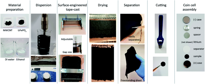
Fig. 1 illustrates the preparation of MWCNT-LiFePO4 sheets using SETC.13 Table 1 shows the sample naming convention. MWCNT flakes, LiFePO4 powders, ethanol and deionized water were mixed at specific ratios according to Table 1. The mixture was then lightly ground using a mortar and pestle for 2 minutes. Then we simultaneously performed sonication using a VCX 750 Ultrasonic Processor (Sonic, USA) and magnetic stirring using advanced hotplate stirrers (VWR, USA) at room temperature. An amplitude of 40% was set for 10 minutes. Magnetic stirring was well maintained during the sonication. The dispersed slurry was then degassed using a vacuum oven. SETC was performed manually at room temperature using a micrometer adjustable film applicator (EQ-Se-KTQ-150, MTI Corporation, USA) with a specific value of doctor-blade gap size to achieve similar mass loading as shown in Fig. S1.† The supporting substrate was copper foil (EQ-bccf-9u, MTI Corporation, USA) with matt-side up. Glass plate (EQ-Tglass, MTI Corporation, USA) was placed beneath the supporting substrate. The casted film was then dried inside an oven (Binder Forced Convection Oven FD 53) at 120 °C for 1 hour. The dried MWCNT-LiFePO4 film can be easily separated using tweezer from copper supporting substrate.| Sample name | wt% MWCNT | wt% LFP | MWCNT (mg) | LiFePO4 (mg) | DI water (ml) | Ethanol (ml) |
|---|---|---|---|---|---|---|
| MWCNT | 100 | 0 | 400 | 0 | 100 | 100 |
| MWCNT-5 wt% LiFePO4 | 95 | 5 | 400 | 21.05 | 100 | 100 |
| MWCNT-10 wt% LiFePO4 | 90 | 10 | 400 | 44.44 | 100 | 100 |
| MWCNT-30 wt% LiFePO4 | 70 | 30 | 400 | 171.43 | 100 | 100 |
| MWCNT-50 wt% LiFePO4 | 50 | 50 | 400 | 400 | 100 | 100 |
| MWCNT-70 wt% LiFePO4 | 30 | 70 | 200 | 466.67 | 50 | 50 |
| MWCNT-80 wt% LiFePO4 | 20 | 80 | 200 | 800 | 50 | 50 |
| MWCNT-90 wt% LiFePO4 | 10 | 90 | 200 | 1800 | 50 | 50 |
| MWCNT-95 wt% LiFePO4 | 5 | 95 | 100 | 1900 | 25 | 25 |
2.3. Preparation of ball milled LiFePO4
Ball milled LiFePO4 powders were prepared with wet ball milling using Tencan QXQM-0.4 Full-Directional Planetary Ball Mill with the following configurations: jar and bead material = zirconium oxide, bead diameter = 5 mm, ball-to-sample mass ratio = 50, speed of rotation = 650 rpm and ball mill time = 30 minutes.2.4. Physical characterizations
Scanning Electron Microscopy (Nova NanoSEM, FEI) was used to determine the morphology of MWCNT-LiFePO4 sheets. No coating of palladium/gold layer was applied to the samples. Energy-dispersive X-ray spectroscopy (EDS) mapping was performed using Quanta 250 ESEM at 20 kV accelerating voltage. Raman spectroscopy was performed using a Witec Alpha 300RAS with 532 nm excitation wavelength. X-ray diffraction was performed using XRD Empyrean from PANalytical XPert PRO using a powder method, with copper Kα1 of 1.540598 Å, 40 kV voltage, 40 mA current, step size of 0.02° and 2θ range from 10° to 80°. Particle sizes of as-received LiFePO4 powders and ball milled LiFePO4 powders were determined using HORIBA LA-950 Particle Size Analyzer. The samples were prepared for measurement of the particle size such that LiFePO4 powders were immersed in water followed by sonication using VCX 750 Ultrasonic Processor (Sonic, USA) for 10 minutes, then particle size measurements were immediately performed using HORIBA LA-950 Particle Size Analyzer.2.5. Electrical conductivity characterizations
In-plane resistivity of freestanding MWCNT-LiFePO4 was measured at room temperature using LakeShore 7607 Hall Measurement System. Samples were cut to 2 cm × 2 cm square and dropped by a tiny amount of silver paste on all corners of the square with van der Pauw configuration. Contact formation using pulsed high current was done to decrease the contact resistance between the probes and samples. Thickness of the samples was measured using cross-section scanning electron microscope (SEM). The electrical conductivity was calculated according to: where σ is the electrical conductivity and ρ is the electrical resistivity.
2.6. Electrochemical characterizations
MWCNT-LiFePO4 sheet was cut using a punch with a diameter of 12 mm for battery cycle test and diameter of 5 mm for cyclic voltammetry test. The mass was measured using a precision balance (Mettler Toledo MS105DU Semi-Micro Analytical Balance) with a readability of 0.01 mg in resolution. The cut samples were heated at 80 °C to remove residual moisture before cell assembly. Coin cells of 2032-type were assembled using a crimping machine (MSK-110 Coin Cell Crimping Machine) inside glovebox (MBraun MB-Labstar 1450/780). The liquid electrolyte used was 1 M LiPF6 in EC![[thin space (1/6-em)]](https://www.rsc.org/images/entities/char_2009.gif) :
:![[thin space (1/6-em)]](https://www.rsc.org/images/entities/char_2009.gif) EMC (1
EMC (1![[thin space (1/6-em)]](https://www.rsc.org/images/entities/char_2009.gif) :
:![[thin space (1/6-em)]](https://www.rsc.org/images/entities/char_2009.gif) 1 vol%) with 2 wt% FEC. A half-cell configuration was used in which a lithium metal foil serves as the anode. Coin cells were tested using a battery test system (Maccor Battery Test System Series 4000) inside an environmental chamber (CSZ Model MC-3 Chamber) at a constant temperature of 25 °C. Battery testing was performed at various rates with a potential window of 2.5–4.0 V vs. Li/Li+. The charging procedure includes constant-current charging at C-rate followed by constant-voltage charging at 4.0 V until the current decreased to 0.05C or 15 minute timeout. The specific capacities were calculated by considering the mass of the whole electrode = mass of MWCNTs + mass of LiFePO4. Cyclic voltammetry was performed at 0.1 mV s−1 scan rate from 2.5–4.0 V vs. Li/Li+, using a multi-channel potentiostat/galvanostat (Princeton Applied Research PMC-1000) without iR compensation.
1 vol%) with 2 wt% FEC. A half-cell configuration was used in which a lithium metal foil serves as the anode. Coin cells were tested using a battery test system (Maccor Battery Test System Series 4000) inside an environmental chamber (CSZ Model MC-3 Chamber) at a constant temperature of 25 °C. Battery testing was performed at various rates with a potential window of 2.5–4.0 V vs. Li/Li+. The charging procedure includes constant-current charging at C-rate followed by constant-voltage charging at 4.0 V until the current decreased to 0.05C or 15 minute timeout. The specific capacities were calculated by considering the mass of the whole electrode = mass of MWCNTs + mass of LiFePO4. Cyclic voltammetry was performed at 0.1 mV s−1 scan rate from 2.5–4.0 V vs. Li/Li+, using a multi-channel potentiostat/galvanostat (Princeton Applied Research PMC-1000) without iR compensation.
3. Results
Freestanding MWCNT-LiFePO4 sheets were produced from MWCNT flakes and LiFePO4 powder precursors using surface-engineered tape-cast (SETC) technique.13 The MWCNTs have inner and outer diameters of 6.4 and 12.4 nm, respectively, and have been thoroughly characterized in ref. 13. Herein, we characterized the as-received LiFePO4 powders. Purity and crystalline structure of the as-received LiFePO4 powders were confirmed by X-ray Diffraction (XRD) studies, as shown in Fig. 2a. All diffraction peaks are well matched and identified as a single phase orthorhombic olivine structure of LiFePO4 (JCPDS # 81-1173) with the space group of Pnma.18 Raman spectra (Fig. 2b) shows the bands at 990 and 1040 cm−1 which correspond to internal stretching vibrations of the PO43− units of γ-Li3Fe2(PO4)3, a laser-induced decomposition of olivine LiFePO4 in air.19 Fig. 2c shows the particle diameter in x axis, the amount of each size by volume (q) in left y axis, and the cumulative below the size (undersize) in right y axis. The as-received LiFePO4 powders have bimodal particle size distribution, mean diameter size of 4.62 μm, and cumulative 10%, 50% and 90% point of diameters (D10, D50 and D90, respectively) of 0.65, 3.55 and 10.17 μm, respectively.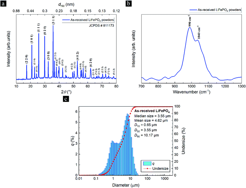 | ||
| Fig. 2 (a) The X-ray diffraction (XRD) pattern, (b) Raman spectra and (c) particle size distribution of as-received LiFePO4 powders. | ||
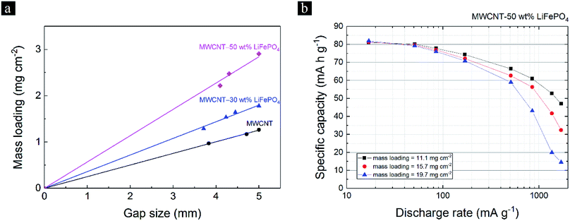
The SETC technique able to control the mass loading of the MWCNT-LiFePO4 sheets by adjusting the film applicator's gap size and/or stacking the layers. Fig. 1 shows the film applicator's gap size can be adjusted by turning the micrometer head. Fig. 3a and Fig. S1† show the mass loading of freestanding MWCNT-LiFePO4 sheets at different LiFePO4/MWCNT mass ratio and different film applicator's gap size. At a fixed wt% of LiFePO4, the mass loading increased with increasing film applicator's gap size. This is due to more precursors being accommodated when large gap size of film applicator is used. The mass loading also increased with increasing the wt% of LiFePO4 at a fixed film applicator's gap size. This is attributed to the dense characteristic of LiFePO4 compared to MWCNT. Since the mass loading significantly affects the specific capacity of MWCNT-LiFePO4, particularly at high discharge rate, see Fig. 3b, it is important to have the same/similar mass loading when comparing different electrode samples.20
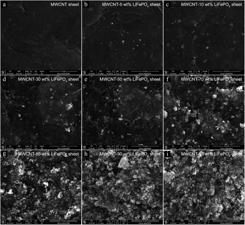
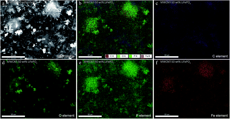
The morphology of MWCNT-LiFePO4 at different LiFePO4/MWCNT mass ratio is shown in Fig. 4. The MWCNTs wrapped the LiFePO4 powders, consistent with ref. 13 and 14. The powders inside MWCNT network corresponded to LiFePO4 as confirmed using energy-dispersive X-ray spectroscopy (EDS) in Fig. 5. The EDS spectra of MWCNT-50 wt% LiFePO4 show the particles comprise of O, P and Fe elements. Fig. 4 shows the spatial density of LiFePO4 in the MWCNT matrix increased with increasing LiFePO4/MWCNT mass ratio. The LiFePO4/MWCNT mass ratio has implications to the electrical conductivity, maximum specific capacity, and processability as explained in the next section.
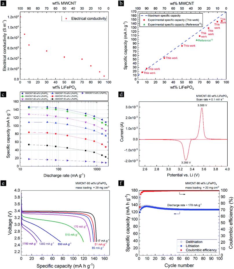
Fig. 6a shows the electrical conductivity of MWCNT-LiFePO4 samples decreased with increasing LiFePO4/MWCNT ratio. It was found that the MWCNTs behaved as conductors that connect LiFePO4 particles to the external load. The electrical conductivity of pristine MWCNT sheet of 1.2 × 10⁴ S m−1 was one order of magnitude higher than that reported in ref. 13 due to a difference in measurement protocols. The electrical conductivity measurement in this work excludes the contact resistance by applying silver paste on the corners of samples and forming excellent contact between samples and probes. In contrast, ref. 13 did not exclude contact resistance from the calculation of electrical conductivity. The electrical conductivity of MWCNT-LiFePO4 sheets in this work fast dropped to 8.7 × 10³, 6.6 × 10³ S m−1 for 5 and 10 wt% LiFePO4, respectively; then slowly dropped to 5.4 × 10³, 4.3 × 10³, 3.9 × 10³ for 30, 50 and 70 wt% LiFePO4, respectively; then fast dropped to 2.6 × 10³, 1.5 × 10³ and 6.3 × 10² for 80, 90 and 95 wt% LiFePO4, respectively. In overall, the electrical conductivities of MWCNT-LiFePO4 samples are still significantly higher than that of pristine LiFePO4 of 3.7 × 10⁻⁷ S m−1.21
The maximum specific capacity of MWCNT-LiFePO4 can be calculated as follows:
The theoretical specific capacity of 100 wt% LiFePO4 is 170 mA h g−1. The MWCNTs theoretically do not store lithium ion at high potential between 2.5 V to 4.0 V vs. Li/Li+, however experimental results show ∼10 mA h g−1 specific capacity due to capacitive current.13 The blue dash line, green triangle point and red square points in Fig. 6b visualized the maximum specific capacity, ref. 13 experimental specific capacity of MWCNT-LiFePO4 (at low discharge rate of 25.4 mA g−1) and this work experimental specific capacity of MWCNT-LiFePO4 (at low discharge rate of 17 mA g−1), respectively. This work experimental specific capacities matched perfectly with theoretical values at low wt% LiFePO4, however at higher wt% LiFePO4, the experimental specific capacities started to deviate from the theoretical values. Fig. 6b shows this work experimental specific capacity increased with increasing wt% LiFePO4 with the value of 17.7, 27.2, 53.7, 84.0, 108.8, 128.9, 144.9 and 146.9 mA h g−1 for MWCNT-LiFePO4 sheets with 5, 10, 30, 50, 70, 80, 90 and 95 wt% LiFePO4, respectively. The tested samples of this work in Fig. 6b and c have average mass loading of 2.9 mg cm−2. Fig. 6b shows a new record of 144.9 mA h g−1 which is larger than that reported in ref. 13 of 98.6 mA h g−1.
With regards to the processability of freestanding sheets, freestanding sheets with composition of 95 wt% LiFePO4 and 5 wt% MWCNT were brittle and not flexible. Increasing the MWCNT content to be ≥10 wt% resulted in the flexible freestanding sheets that are easy to be handled. This is because a minimum amount of MWCNT is needed to achieve network percolation and to have excellent flexibility. We found that 90 wt% LiFePO4 and 10 wt% MWCNT were the optimized composition to achieve a high specific capacity and excellent processability. MWCNT-90 wt% LiFePO4 is the best candidate since it offers high maximum specific capacity, flexible and easy to handle. For applications that require more specific capacity but has relaxed requirement in term of strength and flexibility, one can use MWCNT-95 wt% LiFePO4. Fig. 6d shows the cyclic voltammetry of MWCNT-90 wt% LiFePO4 at 0.1 mV s−1 scan rate results in the cathodic and anodic peaks at 3.293 V and 3.566 V, respectively, and peak potential difference of 0.273 V. The tested samples in Fig. 6e and f have high mass loading of 20 mg cm−2. Fig. 6e shows the MWCNT-90 wt% LiFePO4 has a relatively flat plateau when discharged at low discharge rate of 17 mA g−1, up to a relatively high discharge rate of 170 mA g−1. Our optimized MWCNT-90 wt% LiFePO4 has significantly higher specific capacity of 144.9 mA h g−1 at 17 mA g−1 (133.5 mA h g−1 at 170 mA g−1) compared to previous report13 of 98.6 mA h g−1 at 25.4 mA g−1 (78.81 mA h g−1 at 127 mA g−1). Moreover, the freestanding MWCNT-90 wt% LiFePO4 has a specific capacity of 126.7 mA h g−1 after 100 cycles at 170 mA g−1 discharge rate. This translated into fast discharge in ∼45 minutes which meet the typical cube satellite requirement of being able to be fast discharged in 1 hour or less. Moreover, the performance of MWCNT-LiFePO4 at higher discharge rate (>1700 mA g−1) can be improved by decreasing the LiFePO4 particle size from 3.55 μm to 0.74 μm median size (Fig. S2†) using ball-milling treatment.
4. Conclusions
We optimized the composition of MWCNTs and LiFePO4 powders in MWCNT-LiFePO4 sheets for cathode electrode of lithium-ion batteries. We demonstrated freestanding MWCNT-90 wt% LiFePO4 with excellent specific capacity of 144.9 mA h g−1 at 17 mA g−1 discharge rate. Freestanding MWCNT-90 wt% LiFePO4 has specific capacity of 126.7 mA h g−1 after 100 cycles at a relatively high discharge rate of 170 mA g−1 rate. This specific capacity is higher than previously reported MWCNT-LiFePO4 of 78.81 mA h g−1 at 127 mA g−1 and higher than the maximum specific capacity of typical conventional design of coated LiFePO4 on metal current collector of 120.7 mA h g−1 (based on 71 wt% LiFePO4 active material). In terms of discharge rate, the freestanding MWCNT-90 wt% LiFePO4 met the typical cube satellite requirement of being able to be fast discharged in 1 hour.Conflicts of interest
There are no conflicts to declare.Acknowledgements
This project is part of the implementation plan for the United Arab Emirates Space Agency's ST&I Roadmap and it falls under Level 1 ST&I area of “space power and energy storage” and Level 2 “energy storage“. The project is aimed at developing enabling technologies for promising mission and system concept; in particular, an in-house prototype of lithium-ion battery. The project can potentially result in a commercially viable lithium-ion battery technology for spacecrafts/satellites. This work is funded by the United Arab Emirates Space Agency, Space Missions' Science and Technology Directorate, reference M04-2016-001. The authors acknowledge Applied NanoStructured Solutions (ANS) for providing free samples of MWCNT flakes.References
- X. Wang, L. Sun, X. Hu, R. A. Susantyoko and Q. Zhang, J. Power Sources, 2015, 280, 393–396 CrossRef CAS.
- L. Sun, X. Wang, R. A. Susantyoko and Q. Zhang, J. Mater. Chem. A, 2014, 2, 15294 CAS.
- X. Wang, L. Sun, R. Agung Susantyoko, Y. Fan and Q. Zhang, Nano Energy, 2014, 8, 71–77 CrossRef CAS.
- Q. Xiao, Q. Zhang, Y. Fan, X. Wang and R. A. Susantyoko, Energy Environ. Sci., 2014, 7, 2261 CAS.
- Q. Xiao, Y. Fan, X. Wang, R. A. Susantyoko and Q. Zhang, Energy Environ. Sci., 2014, 7, 655–661 CAS.
- R. A. Susantyoko, X. Wang, L. Sun, W. Sasangka, E. Fitzgerald and Q. Zhang, Nano Energy, 2015, 12, 521–527 CrossRef CAS.
- R. A. Susantyoko, X. Wang, L. Sun, K. L. Pey, E. Fitzgerald and Q. Zhang, Carbon N. Y., 2014, 77, 551–559 CrossRef CAS.
- X. Wang, R. A. Susantyoko, Y. Fan, L. Sun, Q. Xiao and Q. Zhang, Small, 2014, 10, 2826–2829 CrossRef CAS PubMed.
- L. Sun, X. Wang, R. A. Susantyoko and Q. Zhang, Carbon N. Y., 2015, 82, 282–287 CrossRef CAS.
- H.-J. Liao, Y.-M. Chen, Y.-T. Kao, J.-Y. An, Y.-H. Lai and D.-Y. Wang, J. Phys. Chem. C, 2017, 121, 24463–24469 CAS.
- D.-Y. Wang, C.-Y. Wei, M.-C. Lin, C.-J. Pan, H.-L. Chou, H.-A. Chen, M. Gong, Y. Wu, C. Yuan, M. Angell, Y.-J. Hsieh, Y.-H. Chen, C.-Y. Wen, C.-W. Chen, B.-J. Hwang, C.-C. Chen and H. Dai, Nat. Commun., 2017, 8, 14283 CrossRef CAS PubMed.
- Y. Park, G. Park, J. Park and J. Lee, Electrochim. Acta, 2017, 247, 371–380 CrossRef CAS.
- R. A. Susantyoko, Z. Karam, S. Alkhoori, I. Mustafa, C.-H. Wu and S. Almheiri, J. Mater. Chem. A, 2017, 5, 19255–19266 CAS.
- B. S. Lalia, T. Shah and R. Hashaikeh, J. Power Sources, 2015, 278, 314–319 CrossRef CAS.
- Z. Karam, R. A. Susantyoko, A. Alhammadi, I. Mustafa, C.-H. Wu and S. Almheiri, Adv. Eng. Mater., 2018, 1701019 CrossRef.
- B. K. Malet and T. K. ShahGlass Substrates Having Carbon Nanotubes Grown Thereon and Methods for Production Thereof, US Pat. 8784937 B2, 2014.
- T. K. ShahH. LiuJ. M. Goldfinger and J. J. MorberCarbon Nanostructure-Coated Fibers of Low Areal Weight and Methods for Producing the Same, US Pat. 9107292 B2, 2015.
- F. Teng, S. Santhanagopalan, R. Lemmens, X. Geng, P. Patel and D. D. Meng, Solid State Sci., 2010, 12, 952–955 CrossRef CAS.
- E. Markevich, R. Sharabi, O. Haik, V. Borgel, G. Salitra, D. Aurbach, G. Semrau, M. A. Schmidt, N. Schall and C. Stinner, J. Power Sources, 2011, 196, 6433–6439 CrossRef CAS.
- R. A. Susantyoko, X. Wang, Y. Fan, Q. Xiao, E. Fitzgerald, K. L. Pey and Q. Zhang, Thin Solid Films, 2014, 558, 356–364 CrossRef CAS.
- C. Wang and J. Hong, Electrochem. Solid-State Lett., 2007, 10, A65 CrossRef CAS.
Footnote |
| † Electronic supplementary information (ESI) available. See DOI: 10.1039/c8ra01461b |
| This journal is © The Royal Society of Chemistry 2018 |

