 Open Access Article
Vertically-oriented graphene nanosheet as nano-bridge for pseudocapacitive electrode with ultrahigh electrochemical stability†
Pingge He *a,
Qiangqiang Zhangbc,
Qun Huanga,
Boyun Huanga and
Tengfei Chen*a
aState Key Laboratory of Powder Metallurgy, Central South University, Changsha 410083, China. E-mail: pingge@csu.edu.cn; tengfei@csu.edu.cn
bCollege of Civil Engineering and Mechanics, Lanzhou University, Lanzhou 730000, P. R. China
cKey Laboratory of Mechanics on Disaster and Environment in Western China (Lanzhou University), The Ministry of Education of China, Lanzhou 730000, P. R. China
First published on 13th April 2018
Abstract
A hierarchical structure consisting of Ni–Co hydroxide nanosheets (NCHN) electrodeposited on vertically-oriented graphene nanosheets (GN) on carbon cloth (CC) was fabricated for high-performance pseudocapacitive electrodes. NCHN was uniformly distributed on GN, forming a sheet-on-sheet hierarchical structure. Such NCHN/GN/CC hybrid electrodes exhibit high capacitance and ultrahigh electrochemical-stability that structure and electrochemical properties of hybrid electrodes are not affected by the cyclic low-rate scanning (at 5 mV s−1 even over 1000 cycles). GN vertically grown on CC is used as nano-bridge between NCHN active materials and CC current collector, which effectively facilitates ion/charge transfer between the electrolyte and electrode, consequently leading to the ultrahigh electrochemical-stability of hybrid electrodes. To assess functional behavior, two-terminal flexible asymmetric supercapacitor devices with NCHN/GN/CC as positive electrode and GN/CC as negative electrode were assembled and electrochemically treated to demonstrate the ultrahigh electrochemical stability.
1. Introduction
Supercapacitors, with fast power delivery, high rate capability and stable cyclic life, show great promise as next-generation energy storage systems, complementing even replacing batteries as power supplies in practical applications.1–4 Great efforts have been made for the development of supercapacitors, particularly the exploration of novel supercapacitor electrodes. Pseudocapacitive electrode materials, such as metal oxides/hydroxides containing transition metal elements (e.g., Ni, Co, Mn) that are endowed with rich redox states, can significantly improve energy densities of supercapacitors compared to their carbon-based counterparts.5–7 Recently, a novel binary metal oxide (NiCo2O4) and related hydroxide nanostructures have been extensively studied as promising pseudocapacitive electrode materials for supercapacitors because of their low cost, relatively high electrical conductivity and high electrochemical activity compared to single metal oxides/hydroxides.8 However, the high capacitance of such pseudocapacitive electrodes is generally achieved at low scan rates or low current densities, which significantly deteriorate the electrode structure and performance.9,10 The structure and performance instability of pseudocapacitive electrodes over charge/discharge process at low scan rates or low current densities are possibly attributed to the mechanical detachment of the active materials from substrates, excessive volume expansion of active materials, low conductivity and limited mass transfer during charge/discharge processes.9,11 Thus, the design of hierarchical structure with high structural and electrochemical stability is necessary to achieve high-performance and durable supercapacitor electrodes.Numerous templates for metal oxides/hydroxides are developed to enhance the structural stability of electrodes during charge/discharge process. Traditional substrates such as Ni and stainless steel are commonly used while they generally exhibit relatively low specific surface area. Carbon-based nanomaterials such as graphene,12,13 reduced graphene oxide14,15 and carbon nanotubes16 are frequently adopted as nanotemplates for highly pseudocapacitive materials due to their large specific surface area. However, the electrode fabrication process always involves utilization of binder and mechanical mixing, which seriously deteriorates the structural unity and stability of electrodes, leading to poor electrochemical performance.17,18 To alleviate this problem, free-standing electrodes with desirable structural-stability to fully exploit the excellent pseudocapacitive properties of metal oxides/hydroxides are highly required. Meanwhile, rarely has it been reported on the structural evolution of hybrid pseudocapacitive electrodes during the charge/discharge process at low scan rates and its subsequent effects on electrochemical performance of electrodes. The deep understanding of the ion/charge transfer mechanism of electrodes during the charge/discharge process is meaningful and instructive for supercapacitor in their practical applications.
In this work, highly pseudocapacitive Ni–Co hydroxide nanosheet (NCHN) was electrodeposited on vertically-oriented graphene nanosheet (GN) as free-standing and binder-free pseudocapacitive electrodes. The GN layer has been demonstrated its great promise in supercapacitor field, either as active materials (with improved capacitance)4,19 or nanotemplate for pseudocapacitive materials (with high rate capability and excellent cyclic stability).20,21 GN which is vertically grown on carbon cloth (CC) is used as nano-bridge connecting NCHN active materials with CC current collector. The structural evolution of NCHN/GN/CC hybrid electrodes during charge/discharge process was systematically studied through electrochemically treating NCHN/GN/CC electrodes at low scan rates over different cycles. The microstructures and electrochemical properties of hybrid electrodes after treatments are investigated to get a deep understanding of the electrochemical stability mechanism for such hybrid electrodes during cyclic charge/discharge process. Moreover, flexible asymmetric supercapacitors with NCHN/GN/CC as positive electrode, GN/CC as negative electrode and KOH/PVA as both electrolyte and separator were fabricated and electrochemically treated as well to demonstrate the ultrahigh electrochemical stability of such hybrid electrodes.
2. Experimental
2.1 Growth of GN on CC
Carbon cloth substrate (5 × 10 mm2, Epsilon Corp. China) was put into the center of a microwave plasma chemical vapor deposition (MPCVD) furnace. H2 (50 sccm) was first introduced to the MPCVD system and after the total pressure reaches 10 torr, the plasma was turned on (a power of 300 W). Then the total pressure was gradually increased to 25 torr, during which the plasma power gradually increased from 300 to 550 W. Subsequently, CH4 (10 sccm) as the carbon source was introduced. The GN growth was under a MPCVD condition with the plasma power of 550 W, total pressure of 25 torr, and feed gases of H2 (50 sccm) and CH4 (10 sccm). The growth time was 15 min to ensure the CC substrates fully covered by GN. The mass loading of GN is measured to be 1.8 mg cm−2 by the weight difference of the CC sample before and after MPCVD process using a microbalance with an accuracy of 1 μg.2.2 Electrodeposition of NCHN on GN/CC
According to previously reported procedures, NCHN were prepared on GN/CC by an electrodeposition method.20,22 The electrodeposition was conducted by the electrochemical workstation (CHI660C) through a three-electrode system consisting of GN/CC as the working electrode, Pt mesh as the counter electrode and saturated calomel electrode (SCE) as the reference electrode. The NCHN was electrodeposited on GN at a constant potential of −1.0 V vs. SCE in a aqueous solution containing 0.1 M Ni(NO3)2 and 0.03 M Co(NO3)2 at ambient temperature. The electrodeposition duration was 3 min, which has been demonstrated as the optimized time in our previous work.20 The mass loading of NCHN is measured to be approx. 3 mg cm−2 by the weight difference of the sample before and after electrodeposition process. For comparison, NCHN were also electrodeposited on bare CC under the same condition.2.3 Material characterization
The surface morphology of electrodes was characterized by field emission scanning electron microscope (FESEM, Nova Nano 230). The structure and chemical composition of the electrodes were investigated characterized by transmission electron microscopy (TEM, Japan FEM-2100F) combined with energy-dispersive X-ray spectroscopy (EDX) mapping and X-ray diffraction (XRD, D/max 2550).2.4 Electrochemical treatments and characterization
The electrochemical performance was evaluated using an electrochemical workstation (CHI660C). Electrochemical measurements were conducted in a three-electrode configuration at room temperature using 2 M KOH as electrolyte. NCHN/GN/CC served directly as the working electrode. Pt mesh and standard calomel electrode (SCE) were used as the counter electrode and reference electrode, respectively. Electrochemical impedance spectroscopy (EIS) measurements were executed with an AC perturbation amplitude of 5 mV in the frequency range from 0.1 Hz to 1 MHz.In order to investigate effects of low scan rates on the structure and electrochemical properties of NCHN/GN/CC electrodes, the hybrid electrodes were scanned at 5 mV s−1 over 100, 300, 500 and 1000 cycles, respectively. For comparison, NCHN/CC electrodes (without GN) were also electrochemically treated under the same condition.
3. Results and discussion
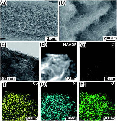
The morphology of NCHN/GN/CC has been shown in Fig. 1. The bare GN grown on CC has been provided in ESI, Fig. S1,† and the detailed mechanism for such vertical GN growth has been systematically reported in previous work.23,24 After electrodeposition time of 3 min, NCHNs are uniformly distributed on the surface of GN (see Fig. 1a). Moreover, the edges of GN are clearly observed with dense NCHN coverage. High-magnification SEM image in Fig. 1b indicates that smaller NCHN with a lateral size of several tens of nanometers covers perpendicularly from the surface of larger GN substrate, forming an island-like morphology. The TEM image in Fig. 1c further confirms the homogeneous distribution of small NCHN (visible dark lines) on large GN, forming a unique sheet-on-sheet hierarchical structure. Energy dispersive X-ray spectrometry (EDX) elemental mapping of NCHN/GN shown in Fig. 1d–h reveals the spatial elemental distribution within the hierarchical structure. Fig. 1d contains a high-angle annular dark field (HAADF) scanning TEM image of numerous NCHN on a magnified portion of a single GN. Fig. 1e–h corresponds to C, Co, Ni and O map, respectively. These spatial elemental mappings reveal a homogeneous spatial distribution of the mapped elements (Ni, Co and O) in the nanosheet structure. The structural uniformity and integrality are the prerequisites for performance stability. The nitrogen (N2) adsorption–desorption isotherms and the corresponding Barret–Joyner–Halenda (BJH) pore size distribution curves of NCHN/GN/CC electrode have been provided in ESI, Fig. S2,† indicating the NCHN/GN/CC electrode presents mesoporous structure, which could facilitate the fast mass transport.25 Moreover, XPS spectra of NCHN/GN/CC hybrid electrode have been provided in ESI, Fig. S3† showing some covalent bonds form between C and O, which suggests that a robust bonding exists at the interface between the NCHN and GN.After electrochemical treatment at a scan rate of 5 mV s−1 over different cycles, hybrid electrodes were systematically characterized through XRD and SEM to investigate the structural evolution. The XRD patterns of electrodes before and after electrochemical treatments are shown in Fig. 2. The XRD pattern of original NCHN/GN/CC electrode (without electrochemical treatment) shows a dominant peak at 26.4° and a small peak at approx. 44°, corresponding to (002) and (101) plane diffraction of graphite crystalline structure (JCPDS number: 41-1487), respectively. Meanwhile, peaks at approx.11.6°, 23.3°, 35° and 60.9° shown in the XRD pattern are attributed to (003), (006), (012) and (110) plane diffraction of a comblainite structure, consisting of Ni, Co, O, H and C elements in a unity structure (JCPDS number: 33-0429).22,26 Some sharp peaks at around 30° and 40° might be attributed to impurities from the original electrode surface. After electrochemical treatments at 5 mV s−1 over 100, 300, 500 and 1000 cycles, NCHN/GN/CC electrodes display few differences in the XRD patterns, indicating the crystalline structure of NCHN/GN/CC electrodes is independent on cyclic charge/discharge process at low scan rates.
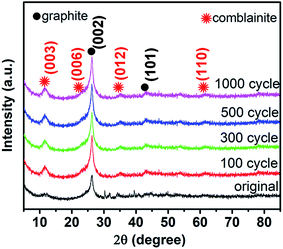 | ||
| Fig. 2 XRD patterns of NCHN/GN/CC electrodes before and after electrochemical treatment at 5 mV s−1 over different cycles. | ||
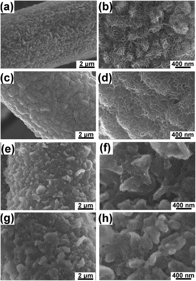
SEM images of NCHN/GN/CC electrodes after different cyclic charge/discharge treatments at a scan rate of 5 mV s−1 (See Fig. 3) reveal the morphology evolution of hybrid electrodes. After 100-cycle electrochemical treatment, GN surface remains a large-scale coverage of NCHN (see Fig. 3a), and edges of GN are clearly distinguished (see Fig. 3b). Small NCHN with numerous edges are homogeneously and densely distributed on GN surface, indicating the intact sheet-on-sheet hierarchical structure after 100-cycle electrochemical treatment. With increasing charge/discharge treatment cycles (300 cycles), a thin layer of NCHN film covers the surface of GN (see Fig. 3c), and less edges of NCHN are observed (see Fig. 3d). After 500-cycle electrochemical treatment, GN surface is covered with a thicker layer of NCHN, especially among the GN edge regions (see Fig. 3e). As shown in Fig. 3f, some NCHN tend to aggregate on GN edges but the sheet-on-sheet hierarchical structure is still remained without structural collapse. In Fig. 3g, the NCHN/GN/CC electrode after 1000-cycle charge/discharge treatment presents some aggregations on the surface as well, while edges of NCHN and GN are clearly distinguished, indicating the high structural-stability of NCHN/GN/CC electrodes. In sharp contrast, SEM images of NCHN/CC electrodes after a 300-cycle charge/discharge treatment at 5 mV s−1 (see ESI, Fig. S4†) show that a large number of NCHN peel off the CC substrate and some NCHN seriously aggregate on carbon fiber surface, indicating severe structural damage and deformation of NCHN/CC electrodes during the cyclic charge/discharge process.
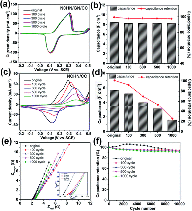
After cyclic charge/discharge treatments at a scan rate of 5 mV s−1, NCHN/GN/CC electrodes were electrochemically characterized in 2 M KOH aqueous electrolyte and the related results are shown in Fig. 4. Fig. 4a displays cyclic voltammetry (CV) curves of treated NCHN/GN/CC electrodes at a scan rate of 5 mV s−1 (CV curves of treated NCHN/GN/CC electrodes at different scan rates are provided in ESI, Fig. S5†). All the CV curves almost overlap and show few differences in the location of redox peaks (the negligible shift in the CV curves could be attributed to the increased ion-diffusion resistance, and redox peaks correspond to the redox reactions between NCHN and KOH electrolyte27,28), independent of treating cycle numbers, which indicate the electrochemical properties of NCHN/GN/CC electrodes do not change after cyclic charge/discharge treatments even at low scan rates. Moreover, overlapped galvanostatic charge/discharge profiles of NCHN/GN/CC electrodes after treatments (see ESI, Fig. S6a†) further confirm the high electrochemical-stability during cyclic charge/discharge process. The capacitances of NCHN/GN/CC electrodes after treatments calculated from galvanostatic charge/discharge curves at a current density of 5 mA cm−2 have been provided in Fig. 4b. The NCHN/GN/CC electrodes exhibit an areal capacitance of 8.25, 8.27, 8.24 and 8.22 F cm−2 after 100-, 300-, 500-, and 1000-cycling treatments, respectively. Compared to the original NCHN/GN/CC electrode (8.4 F cm−2), the capacitance retentions are over 98% after cyclic charge/discharge treatments at a low scan rate.
For comparison, NCHN/CC electrodes after electrochemical treatments were electrochemically investigated as well. Fig. 4c shows huge differences in CV curves at 5 mV s−1 of treated NCHN/CC electrodes. After 100-cycle treatment, the redox peaks move positively, and the current (particularly the discharge current) significantly decreases, indicating the great decrease in the capacitance of electrodes. Moreover, with further increasing cycles of treatments, redox peaks become much milder and currents undergo a continuous attenuation. Galvanostatic charge/discharge curves of NCHN/CC electrodes after different cycling treatments provided in ESI, Fig. S6b† indicate with increasing cycles during low-rate scanning treatments, voltage plateaus on charge/discharge profiles of NCHN/CC electrodes are not obvious, and the time period required for charge and discharge process remarkably decreases, which are consistent with the CV results. The capacitances of NCHN/CC electrodes after low rate-scanning treatments calculated from charge/discharge curves at a current density of 5 mA cm−2 have been provided in Fig. 4d. The NCHN/CC electrodes present an areal capacitance of 5.21, 3.99, 3.11 and 1.58 F cm−2, with a capacitance retention of 90%, 70%, 54.5% and 27.6% after 100-, 300-, 500-, and 1000-cycling treatments, respectively, indicating a significant decrease in capacitance after cyclic charge/discharge process at low scan rates. Moreover, the capacitance drops remarkably with increasing cycles during the treatments. The sharp comparison of electrochemical stability between NCHN/GN/CC and NCHN/CC electrodes reveals that GN as nano-bridge between pseudocapacitive materials and current collectors plays an essential role in the structural and electrochemical stability of hybrid electrodes during the low-rate scanning charge/discharge process. Furthermore, comparative EIS data of NCHN/GN/CC and NCHN/CC has been provided in the ESI, Fig. S7,† which demonstrates the NCHN/GN/CC electrode exhibits lower equivalent-series-resistance and higher charge transfer efficiency.
Capacitance retentions of NCHN/GN/CC electrodes after treatments are plotted as a function of current density (See ESI, Fig. S8†). As the current density increases from 5 to 100 mA cm−2, all the capacitances of NCHN/GN/CC electrodes undergo a slight decrease, with a capacitance retention of over 88%, which is independent on the treatment cycle. Nyquist plots of NCHN/GN/CC electrodes after treatments are shown in Fig. 4e, in which few differences are present. From the magnified EIS in the inset of Fig. 4e, the equivalent-series-resistance (Re) value, measured from the real-axis intercept of the impedance spectrum at high frequencies, increases slightly from approx. 2.1 to 2.4 Ω after 1000-cycle treatment on electrodes. Moreover, all Nyquist plots show negligible semicircle features at high frequencies, indicating the high charge transfer efficiency of hybrid electrodes. The cycle life of NCHN/GN/CC electrodes before and after treatments provided in Fig. 4f is evaluated over 10![[thin space (1/6-em)]](https://www.rsc.org/images/entities/char_2009.gif) 000 galvanostatic charge/discharge cycles at a current density of 60 mA cm−2. For the original NCHN/GN/CC electrode, the capacitance exhibits a slight increase during the first 3000 cycles and then undergoes a gradual attenuation through the 10000th cycle, with overall capacitance retention of approx. 92% compared to the first cycle. The gradual increase of capacitance in early cycles has been observed for many metal oxide or hydroxide containing electrodes in prior work and hypothetically explained by the gradually ameliorated electrolyte penetration/wetting of the electrodes by the electrolyte and structural activation.29,30 After cyclic treatment at low scan rates, the hybrid electrodes exhibit gradual decrease in capacitance, but still with high capacitance retentions over 90% during 10
000 galvanostatic charge/discharge cycles at a current density of 60 mA cm−2. For the original NCHN/GN/CC electrode, the capacitance exhibits a slight increase during the first 3000 cycles and then undergoes a gradual attenuation through the 10000th cycle, with overall capacitance retention of approx. 92% compared to the first cycle. The gradual increase of capacitance in early cycles has been observed for many metal oxide or hydroxide containing electrodes in prior work and hypothetically explained by the gradually ameliorated electrolyte penetration/wetting of the electrodes by the electrolyte and structural activation.29,30 After cyclic treatment at low scan rates, the hybrid electrodes exhibit gradual decrease in capacitance, but still with high capacitance retentions over 90% during 10![[thin space (1/6-em)]](https://www.rsc.org/images/entities/char_2009.gif) 000 cycles, which indicates an excellent long-term cyclic stability of such hybrid electrodes even after cyclic treatments at low scan rates. Moreover, the cycling stabilities of NCHN/CC electrodes before and after treatments have also been provided in the ESI, Fig. S9.†
000 cycles, which indicates an excellent long-term cyclic stability of such hybrid electrodes even after cyclic treatments at low scan rates. Moreover, the cycling stabilities of NCHN/CC electrodes before and after treatments have also been provided in the ESI, Fig. S9.†
To demonstrate the practical feasibility that GN as nano-bridge between NCHN and CC improves their electrochemical stability during charge/discharge process, we assembled flexible asymmetric supercapacitor devices consisting of GN/CC as negative electrode (the CV curves of GN/CC electrode measured using 2 M KOH as electrolyte have been provided in ESI, Fig. S10†), NCHN/GN/CC as positive electrode, and KOH/PVA as both electrolyte and separator (detailed fabrication procedures are provided in ESI†), and electrochemically treating the device at a low scan rate of 5 mV s−1 over 100, 300 and 500 cycles. The electrochemical performance of two-terminal asymmetric supercapacitor device before and after treatment is shown in Fig. 5.
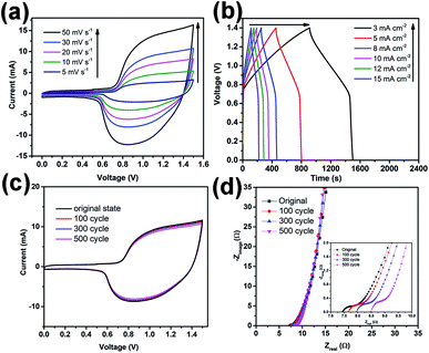
Fig. 5a displays CV profiles of the asymmetric device before electrochemical treatment at different scan rates from 5 to 50 mV s−1 with a voltage window of 0–1.5 V. Two redox peaks are observed in the CV curves at all scan rates that are attributed to the redox reactions between NCHN active material and KOH electrolyte. Galvanostatic charge/discharge curves at different current densities ranging from 3 to 15 mA cm−2 are provided in Fig. 5b. The charge/discharge curves show obvious voltage plateaus, which are consistent with voltages of the redox peaks in CV curves. The Ragone plots of the present asymmetric device compared with contemporary supercapacitors have been provided in ESI, Fig. S11,† demonstrating the excellent electrochemical performance of the asymmetric supercapacitor device. For practical applications, leakage current and self-discharge should be minimal, and these characteristics of the asymmetric supercapacitors are provided in ESI, Fig. S12.† The leakage current was measured by keeping the supercapacitor at a constant voltage of 1.5 V for 24 h. The obtained data in Fig. S12a† indicates that leakage current drops quickly at an initial stage and gradually stabilizes, reaching 0.0015 mA after maintaining a constant voltage for 24 h. Such a low leakage current indicates good capacitor performance, which could be attributed to few shuttle reactions caused by the impurities in electrode materials.31,32 Fig. S12b† displays the self-discharge profile of the flexible asymmetric supercapacitor under such an open-circuit voltage condition. The asymmetric supercapacitor maintains approx. 52% of the initial potential after 24 h of self-discharge. These leakage current and self-discharge characteristics of the asymmetric supercapacitor corroborate that the devices are promising for use in future energy storage system.
After electrochemical treatment at low scan rates over different cycles, the device presents almost overlapped CV curves measured at a scan rate of 30 mV s−1 (see Fig. 5c). The highly repeatable CV characteristic further demonstrates the high electrochemical stability of the present device. Furthermore, Nyquist plots of the devices before and after treatments are provided in Fig. 5d, only showing a few fluctuations. From the inset of Fig. 5d, the Re value of device before treatment is approx. 7.5 Ω and after treatments at a scan rate of 5 mV s−1 over 100, 300 and 500 cycles, Re value increases to 7.6, 8 and 8.5 Ω, respectively, indicating a small increase in the equivalent-series-resistance after cyclic treatment at low scan rates. Moreover, all the curves (before or after treatments) show small semicircles, indicating high charge transfer efficiency of the devices (the small charge transfer resistance might be attributed to various factors).
To get a deep understanding of the high electrochemical-stability of NCHN/GN/CC hybrid electrode, the ion transfer mechanism during charge/discharge process is further investigated. The electrochemical performance is highly dependent on the electrode structure, while the electrode structural change during charge/discharge process is expected to be affected by the amount of active materials reduced or oxidized, which is determined by the scan rate (current density), and the diffusion path (diffusion time).9,33 During low-rate scanning process, the diffusion time is the main factor influencing the structural and performance stability of electrodes. Herein, the mechanisms for ion transfer of hybrid electrodes (NCHN/GN/CC and NCHN/CC) during charge/discharge process are schematically illustrated as shown in Fig. 6. For NCHN/GN/CC hybrid electrodes, ions transfer following the path as: electrolyte → NCHN (active material) → GN (nano-bridge) → CC (current collector). GN as nano-bridge effectively connects NCHN and CC and the continuous atom transition between GN and CC34 further eliminates the interfacial barrier for ion transfer, therefore shortening ion diffusion time and facilitating ion rapid diffusion between electrolyte and current collector during the cyclic charge/discharge process (at low scan rates). However, for NCHN/CC hybrid electrodes, the interface between NCHN and CC hinders ion transfer, contributing to a large number of ions retention among NCHN. As a result, electrolyte ions exceedingly react with NCHN active materials, leading to seriously structural deformation of electrodes and subsequent deteriorating effects on performance. GNs as nano-bridge between NCHN active material and CC current collector effectively provides a rapid channel for ion/charge transfer. Moreover, the robust interfacial bonding is a prerequisite to ensure the structural stability and performance durability of NCHN/GN/CC hybrid electrodes.
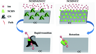 | ||
| Fig. 6 Schematic of ion transfer mechanisms for NCHN/GN/CC and NCHN/CC hybrid electrodes during charge/discharge process. | ||
4. Conclusions
In summary, GN was grown on CC through MPCVD for NCHN electrodeposition as high-performance supercapacitor electrodes. The structural evolution of NCHN/GN/CC hybrid electrodes at low scan rates and its subsequent influences on the electrochemical properties are systematically investigated through studying the microstructure and performance of electrodes that underwent low-rate scanning over different cycles. The results reveal that the structure and electrochemical performance of hybrid electrodes are highly independent on scan cycle at low scan rates, showing ultrahigh electrochemical-stability. To further demonstrate the practical functionality, flexible asymmetric supercapacitors based on such hybrid electrodes are prepared and exhibit high electrochemical-stability as well. The ultrahigh electrochemical-stability of such hybrid structures during charge/discharge process are mainly attributed to that GNs as nano-bridge connecting active material and current collector, on one hand facilitates ion transfer between electrolyte and current density, and on the other hand provides a robust interfacial bonding to ensure the structural stability and performance durability of hybrid electrodes during cyclic charge/discharge process. The present results demonstrate that hybrid NCHN/GN/CC structures are particularly well-suited for practical implementation as a high-performance, durable electrode at low scan rates.Conflicts of interest
There are no conflicts to declare.Acknowledgements
The authors gratefully acknowledge support from the National Natural Science Foundation of China, (PI: Dr Boyun Huang, Grant: No. 51021063, PI: Dr Qiangqiang Zhang, Grant: No. 51702142), National High-tech Research & Development Program of China (863 Program, No. 2012AA03A207), Key Laboratory of Mechanics on Disaster and Environment in Western China (Lanzhou University) (Grant: No. lzujbky-2017-kb03) and the Fundamental Research Funds for the Central Universities (PI: Dr Qiangqiang Zhang, Grant: No. lzujbky-2017-k17). The authors also thank Prof. Fisher and Prof. Xiong for the help and discussion involved in this work.Notes and references
- Y. Zhu, S. Murali, M. D. Stoller, K. J. Ganesh, W. Cai, P. J. Ferreira, A. Pirkle, R. M. Wallace, K. A. Cychosz and M. Thommes, Science, 2011, 332, 1537–1541 CrossRef CAS PubMed.
- P. Simon and Y. Gogotsi, Nat. Mater., 2008, 7, 845 CrossRef CAS PubMed.
- L. L. Zhang and X. Zhao, Chem. Soc. Rev., 2009, 38, 2520–2531 RSC.
- Q. Zhang, Y. Wang, B. Zhang, K. Zhao, P. He and B. Huang, Carbon, 2018, 127, 449–458 CrossRef CAS.
- G. Wang, L. Zhang and J. Zhang, J. Cheminf., 2012, 43, 797–828 Search PubMed.
- P. He, L. Liu, W. Song, G. Xiong, T. S. Fisher and T. Chen, RSC Adv., 2015, 5, 31837–31844 RSC.
- X. Cao, Y. Shi, W. Shi, G. Lu, X. Huang, Q. Yan, Q. Zhang and H. Zhang, Small, 2011, 7, 3163–3168 CrossRef CAS PubMed.
- P. He, Q. Huang, B. Huang and T. Chen, RSC Adv., 2017, 7, 24353–24358 RSC.
- Q. Li, J. M. Anderson, Y. Chen and L. Zhai, Electrochim. Acta, 2012, 59, 548–557 CrossRef CAS.
- W. Wei, X. Cui, W. Chen and D. G. Ivey, Electrochim. Acta, 2009, 54, 2271–2275 CrossRef CAS.
- H. Jiang, C. Li, T. Sun and J. Ma, Chem. Commun., 2012, 48, 2606–2608 RSC.
- C. Zhang, T. Kuila, N. H. Kim, S. H. Lee and J. H. Lee, Carbon, 2015, 89, 328–339 CrossRef CAS.
- C. Zhang, T. Kuila, N. H. Kim, S. H. Lee and J. H. Lee, Carbon, 2015, 89, 328–339 CrossRef CAS.
- C. Zhang, X. Geng, S. Tang, M. Deng and Y. Du, J. Mater. Chem. A, 2017, 5, 5912–5919 CAS.
- B. Dong, X. Zhang, X. Xu, G. Gao, S. Ding, J. Li and B. Li, Carbon, 2014, 80, 222–228 CrossRef CAS.
- S. Abouali, M. Akbari Garakani, Z.-L. Xu and J.-K. Kim, Carbon, 2016, 102, 262–272 CrossRef CAS.
- G. Zhu, Z. He, J. Chen, J. Zhao, X. Feng, Y. Ma, Q. Fan, L. Wang and W. Huang, Nanoscale, 2014, 6, 1079–1085 RSC.
- S. Ye, J. Feng and P. Wu, ACS Appl. Mater. Interfaces, 2013, 5, 7122–7129 CAS.
- G. Xiong, P. He, Z. Lyu, T. Chen, B. Huang, L. Chen and T. S. Fisher, Nat. Commun., 2018, 9, 790 CrossRef PubMed.
- G. Xiong, P. He, D. Wang, Q. Zhang, T. Chen and T. S. Fisher, Adv. Funct. Mater., 2016, 26, 5460–5470 CrossRef CAS.
- G. Xiong, P. He, L. Liu, T. Chen and T. S. Fisher, J. Mater. Chem. A, 2015, 3, 22940–22948 CAS.
- Y.-M. Wang, X. Zhang, C.-Y. Guo, Y.-Q. Zhao, C.-L. Xu and H.-L. Li, J. Mater. Chem. A, 2013, 1, 13290–13300 CAS.
- J. Zhao, M. Shaygan, J. r. Eckert, M. Meyyappan and M. H. Rümmeli, Nano Lett., 2014, 14, 3064–3071 CrossRef CAS PubMed.
- G. Xiong, K. Hembram, D. N. Zakharov, R. G. Reifenberger and T. S. Fisher, Diamond Relat. Mater., 2012, 27, 1–9 CrossRef.
- S.-Q. Fan, B. Fang, J. H. Kim, J.-J. Kim, J.-S. Yu and J. Ko, Appl. Phys. Lett., 2010, 96, 063501 CrossRef.
- H. Chen, L. Hu, M. Chen, Y. Yan and L. Wu, Adv. Funct. Mater., 2014, 24, 934–942 CrossRef CAS.
- V. Gupta, S. Gupta and N. Miura, J. Power Sources, 2008, 175, 680–685 CrossRef CAS.
- X. Wang, A. Sumboja, M. Lin, J. Yan and P. S. Lee, Nanoscale, 2012, 4, 7266–7272 RSC.
- S. K. Meher and G. R. Rao, J. Phys. Chem. C, 2011, 115, 15646–15654 CAS.
- J. W. Lee, A. S. Hall, J. D. Kim and T. E. Mallouk, J. Cheminf., 2012, 43, 1158–1164 Search PubMed.
- G. Xiong, C. Meng, R. G. Reifenberger, P. P. Irazoqui and T. S. Fisher, Adv. Energy Mater., 2014, 4, 1300515 CrossRef.
- H. Wada, K. Yoshikawa, S. Nohara, N. Furukawa, H. Inoue, N. Sugoh, H. Iwasaki and C. Iwakura, J. Power Sources, 2006, 159, 1464–1467 CrossRef CAS.
- M. Toupin, T. Brousse and D. Bélanger, Chem. Mater., 2002, 14, 3946–3952 CrossRef CAS.
- T. Bhuvana, A. Kumar, A. Sood, R. H. Gerzeski, J. Hu, V. S. Bhadram, C. Narayana and T. S. Fisher, ACS Appl. Mater. Interfaces, 2010, 2, 644–648 CAS.
Footnote |
| † Electronic supplementary information (ESI) available. See DOI: 10.1039/c8ra01537f |
| This journal is © The Royal Society of Chemistry 2018 |

