 Open Access Article
An electrochemical anodization strategy towards high-activity porous MoS2 electrodes for the hydrogen evolution reaction†
Xuerui Maoa,
Tianliang Xiaoa,
Qianqian Zhangb and
Zhaoyue Liu *a
*a
aKey Laboratory of Bio-Inspired Smart Interfacial Science and Technology of Ministry of Education, School of Chemistry, Beihang University, Beijing 100191, P. R. China. E-mail: liuzy@buaa.edu.cn; Tel: +86-10-82317801
bKey Laboratory of Micro-nano Measurement, Manipulation and Physics of Ministry of Education, School of Physics and Nuclear Energy Engineering, Beihang University, Beijing 100191, P. R. China
First published on 23rd April 2018
Abstract
Molybdenum disulfide (MoS2) is a promising non-precious metal electrocatalyst for the hydrogen evolution reaction (HER). Herein, we have described an anodization route for the fabrication of porous MoS2 electrodes. The active porous MoS2 layer was directly formed on the surface of a Mo metal sheet when it was subjected to anodization in a sulfide-containing electrolyte. The Mo sheet served as both a supporter for MoS2 electrocatalysts and a conductive substrate for electron transport. After optimizing the anodization parameters, the anodized MoS2 electrode showed a high electrocatalytic activity with an onset potential of −0.18 V (vs. RHE) for the HER, a Tafel slope of ∼101 mV per decade and an overpotential of 0.23 V at a current density of 10 mA cm−2 for the HER. These results indicate that our facile anodization strategy is an efficient route towards a high-activity MoS2 electrode.
1. Introduction
Hydrogen is considered to be an ideal energy carrier because of its cleanliness and renewability. The electrochemical achievement of the hydrogen evolution reaction (HER), when using precious metals, means that it is one of the most efficient technologies used to produce hydrogen.1 Due to the rarity and high cost of precious metals, the development of non-precious metal materials for the HER is therefore necessary.2–5 MoS2, a typical non-precious electrocatalyst for the HER, has recently attracted significant attention because of its low cost and excellent catalytic activity.6,7 MoS2 electrodes have been developed via the immobilization of MoS2 nanoparticles or nanosheets onto various conductive substrates using methods such as chemical vapor deposition,8–12 high-temperature sulfurization,13–18 solvothermal/hydrothermal synthesis,19–27 chemical exfoliation,28–31 electrodeposition,32–34 and photocatalytic reactions.35 However, these methods always require a high temperature, extreme pressure, complex precursors or a long reaction time. The development of an alternative route towards MoS2 electrodes is of significant importance.Electrochemical anodization is a versatile method for the deposition of functional materials onto the surface of metal substrates. Due to the variability of the components, i.e. metal substrate and electrolyte, electrochemical anodization can be used to fabricate various functional oxides or non-oxides facilely. For example, nanotubular or nanoporous structures of TiO2,36–39 Fe2O3,40,41 WO3,42–44 Ta2O5,45–48 MoOx (ref. 10, 49 and 50) and CdS51 have been reported and they were formed via anodization of the corresponding metal in the optimized electrolyte. Considering that the electrocatalyst needs to be fixed onto a conductive substrate for the HER, electrochemical anodization is a very suitable route towards MoS2 electrodes.
Herein, we have reported the fast synthesis of porous MoS2 electrocatalysts on pure Mo metal via electrochemical anodization at room temperature and ambient pressure. The Mo metal served as both a molybdenum source and a conductive substrate for MoS2. The resulting MoS2 electrocatalysts were immobilized on the surface of Mo metal sheets, which could be used as electrodes for the HER directly. After optimizing the anodization parameters, the anodized MoS2 electrode exhibited a high electrocatalytic activity for the HER.
2. Experimental section
2.1 Synthesis of MoS2 electrodes via electrochemical anodization
The porous MoS2 electrode was prepared via one-step anodization in a two-electrode electrochemical cell using platinum foil as a cathode. The anode was a pure Mo sheet (Alfa Aesar), which acted as the Mo source. Before anodization, the Mo sheet was sonicated in acetone, isopropanol and deionized water in sequence. The electrolyte was 0.2 M Na2S (Xilong Chemicals, China) aqueous solution, which served as the sulfur source. The thickness of the anodized MoS2 layer was controlled by altering the anodization parameters, such as voltage and reaction time.2.2 Materials characterization
The morphology of the anodized MoS2 layer was investigated using a FEI Quanta FEG 250 environmental scanning electron microscope (SEM) and a FEI JEM-1200EX transmission electron microscope (TEM). The energy dispersive X-ray spectra (EDX) of the MoS2 electrode were obtained using a JSM-7500F field-emission scanning electron microscope (JEOL, Japan) coupled with an INCA Energy 250 energy spectrum analyzer. The chemical composition of the MoS2 layers was investigated using a Thermo escalab 250XI X-ray Photoelectron Spectrometer (XPS). The amorphous phase of the anodized MoS2 layer was confirmed by measurement of the X-ray diffraction patterns (XRD, Bruker D8 FOCUS X-ray diffractometer).2.3 Electrochemical measurements
The electrocatalytic activity of the anodized MoS2 electrodes for the HER was studied by measuring their polarization curves in 0.5 M N2-purged H2SO4 solution using a three-electrode electrochemical configuration. The Tafel curves were calculated from the polarization curves. The anodized MoS2 electrode with a geometric area of 1 cm2 was used as a working electrode. The reference electrode was Ag/AgCl in 3.5 M KCl and the counter electrode was a platinum wire. The polarization potentials were obtained using a CHI660D electrochemical workstation (Shanghai Chenhua Apparatus Co., China) with a scan rate of 5 mV s−1. The polarization potential was calibrated against a reversible hydrogen electrode (RHE) based on the following equation: φ (vs. RHE) = φ (vs. Ag/AgCl) + 0.205 V. Electrochemical impedance spectroscopy (EIS) was carried out in 0.5 M H2SO4 solution at a potential of −0.2 V (vs. RHE). The frequency range was from 100 kHz to 0.01 Hz.3. Results and discussion
During electrochemical anodization, the Mo metal acted as a Mo source and the sulfide ion in the electrolyte served as a sulfur source for MoS2. When a positive voltage is applied to a Mo metal in Na2S electrolyte, the Mo metal will be oxidized to Mo4+, which subsequently reacts with S2− to form MoS2 on the metal surface as follows:| Mo → Mo4+ + 4e |
| Mo4+ + 2S2− → MoS2 |
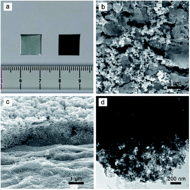
When the Mo sheet was anodized at 2.0 V for 10 min, the metallic luster of the Mo sheet disappeared and a uniform black MoS2 layer was formed (Fig. 1a). The anodized MoS2 layer demonstrated a micro-/nano-structured surface that consisted of some nanosized particles (80–107 nm) on microsized MoS2 blocks (1.7–2.3 μm) (Fig. 1b). Energy dispersive X-ray spectroscopy (EDX) revealed the existence of Mo and S elements in the particles and blocks from the overlapped characteristic peaks of Mo and S at ∼2.3 keV (Fig. S1†). The cross-sectional image (Fig. 1c) indicates that the interior of the MoS2 layer shows a porous structure, which might result from the localized dissolution of Mo metal into the electrolyte during anodization. The thickness of the MoS2 layer was determined to be about 1.2 μm. The porous structure of the MoS2 layer was further confirmed from the TEM measurement, which indicated that there were some nanopores in the anodized MoS2 layer (Fig. 1d).
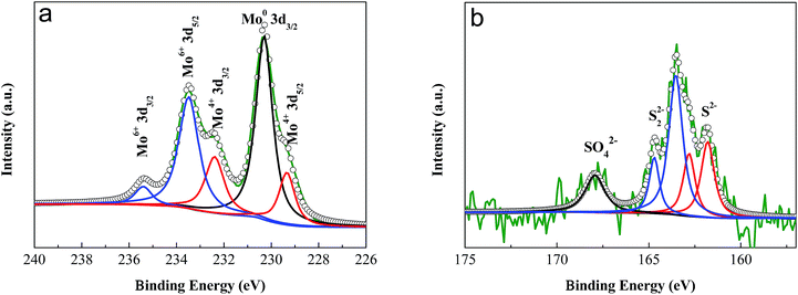
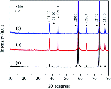
The valences of the molybdenum and sulfur elements in the anodized layer were investigated using X-ray Photoelectron Spectroscopy (XPS). The spectra of the molybdenum 3d orbitals revealed a mixture of Mo oxidation states (Fig. 2a). After peak fitting, the two peaks at 229.3 eV and 232.4 eV were assigned to the 3d5/2 and 3d3/2 orbitals, respectively, for the +4 oxidation state.10,52 The peaks at 235.5 eV and 233.5 eV indicate the existence of the higher +6 oxidation states, probably due to the formation of MoO3 during the process of anodization.52,53 The peak at 230.3 eV was ascribed to the original Mo metal.53 From the spectrum of the sulfur 2p orbital (Fig. 2b), a single doublet at 161.8 eV and 162.8 eV could be observed, which was ascribed to the S 2p3/2 and 2p1/2 orbitals of S2−, respectively.10,54,55 The peaks at 163.5 eV and 164.7 eV indicated the existence of bridging S22−.54–57 The small peak at 168.0 eV corresponds to the binding energy of sulfur in a sulfate ion,52,58,59 which might result from the oxidation of S2− during anodization. The X-ray diffraction patterns (XRD) showed that no resolved diffraction peaks could be detected except for the peaks for the Mo metal and Al supporter, indicating an amorphous phase for the anodized MoS2 layer (Fig. 3). The very weak diffraction peaks at 10–30° may be indexed to MoO3.
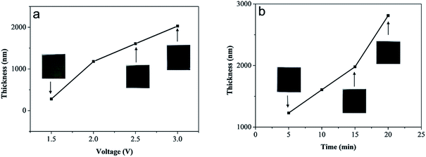
The thickness of the anodized MoS2 layer could be controlled by altering the anodization parameters, such as voltage and reaction time. As shown in Fig. 4a, when the anodization time was fixed at 10 min, the thickness of the MoS2 layer increased from ∼280 nm to ∼2.0 μm along with the increase in voltage from 1.5 to 3.0 V (Fig. S2†). The visible color of the anodized MoS2 layer changed from light brown to black. Note that when the anodization voltage was lower than 2.5 V, the MoS2 layer was fixed onto the Mo substrate tightly. However, when the voltage reached 3.0 V, the MoS2 layer became loose and easily detached from the substrate. Furthermore, if the anodization voltage remained at 2.5 V, the increase in the reaction time from 5 to 20 min led to an increase in the thickness of the MoS2 layer from ∼1.2 μm to ∼2.8 μm (Fig. 4b and S2†). The visible color of the anodized MoS2 layer remained almost unchanged. Our results indicate clearly that the thickness of the MoS2 layer could be controlled facilely during electrochemical anodization.
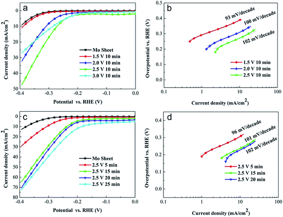
The electrocatalytic activity of the anodized MoS2 electrodes for the HER was investigated by measuring their polarization curves in 0.5 M H2SO4 solution. The electrocatalytic activity was evaluated from the overpotential at a current density of 10 mA cm−2 (j = 10 mA cm−2) for the HER. As shown in Fig. 5a, the pure Mo sheet, prior to anodization, showed a very low electrocatalytic activity for the HER. The overpotential at j = 10 mA cm−2 of the pure Mo sheet was 0.40 V. The low anodization voltage of 1.5 V did not obviously improve the current density because of the thin MoS2 layer (∼280 nm). However, when the pure Mo sheet was anodized at 2.0 V for 10 min (the thickness of the MoS2 layer was ∼1.2 μm), the overpotential at j = 10 mA cm−2 was significantly reduced to 0.31 V, which indicates that the anodized MoS2 layer could be used as an efficient electrocatalyst for the HER. The further increase in the anodization voltage improved the electrocatalytic activity of the MoS2 electrode because of the increase in the thickness of the MoS2 layer. As shown in Fig. 5a, when the Mo sheet was anodized at 2.5 V for 10 min, the MoS2 electrode (thickness = 1.6 μm) exhibited an onset potential of −0.21 V (vs. RHE) for the HER and a low overpotential of 0.26 V at j = 10 mA cm−2. When the anodization voltage was increased to 3.0 V, the MoS2 layer easily detached from the substrate. Although the thickness of the MoS2 layer increased to 2.0 μm, the current density of the MoS2 electrode decreased obviously. These results might be ascribed to the easy detachment of the MoS2 layer during the HER.
In principle, the HER in acidic solution involves the following three possible reactions:
| H3O+ + e1− → Hads + H2O (Volmer reaction) |
| Hads + Hads → H2 (Tafel reaction) |
| Hads + H3O+ + e1− → H2 + H2O (Heyrovsky reaction) |
The combination of the Volmer–Tafel or Volmer–Heyrovsky reaction can lead to the production of molecular H2. Commonly, if the Volmer reaction is the rate-determining step for the HER, the Tafel slope is ∼120 mV. However, a rate-determining step of the Heyrovsky or Tafel reaction produces a Tafel slope of ∼40 or ∼30 mV, respectively.21,32,33 Therefore, based on the calculated value of the Tafel slope, we can determine the rate-determining step for the HER. From Fig. 5a, we calculated the Tafel slopes of the MoS2 electrodes prepared via anodization at 1.5, 2.0 and 2.5 V for 10 min to be 93, 100 and 102 mV per decade, respectively (Fig. 5b), suggesting that they did not show a significant dependence on the anodization voltage. The Tafel slopes of our anodized MoS2 electrodes were close to ∼120 mV, which indicates that the Volmer reaction is the rate-determining step in the HER.
The electrocatalytic activity of our anodized MoS2 electrodes for the HER could also be optimized by altering the anodization time. As shown in Fig. 5c, when the anodization voltage was fixed at 2.5 V, the increase in the anodization time enhanced the current density in the HER. However, the corresponding Tafel slope did not show a significant dependence on the anodization time (Fig. 5d). When the anodization time was 15 min, the anodized MoS2 electrode with a thickness of 2.0 μm demonstrated an onset potential of −0.18 V (vs. RHE) for the HER and an overpotential of 0.23 V at j = 10 mA cm−2. The corresponding Tafel slope was calculated to be 101 mV per decade (Fig. 5d). The current density of this MoS2 electrode for the HER at a potential of −0.3 V (vs. RHE) remained almost constant after 10 min of the HER, which indicates good stability (Fig. S3†). Note that further increasing the anodization time to 20 or 25 min did not improve the electrocatalytic activity obviously. The electrocatalytic activity of the MoS2 electrodes prepared with different anodization times should be related to their charge transfer resistances in the HER. As shown in Fig. S4,† the original Mo metal shows a very high charge transfer resistance in the HER, which was reduced obviously by the anodization reaction. When the anodization time increased from 5 to 15 min, the charge transfer resistance of the MoS2 electrode decreased greatly to a very low value (∼5.2 Ω) because of the increased catalytic sites, which subsequently resulted in a high electrocatalytic activity. Following the further increase in anodization time, although the thickness of the MoS2 layer increased, the charge transfer resistance remained almost unchanged because of the excess MoS2 catalyst, which could not make contact with the electrolyte (i.e. the catalytic sites are enough for the HER). Therefore, the electrocatalytic activity did not demonstrate an obvious improvement. The onset potential of −0.18 V (vs. RHE) for the HER in our work was comparable to that of pure MoS2 electrodes prepared by other methods,10,16,22–24,28,31 which indicates that our anodization strategy is an efficient route towards a high-activity MoS2 electrode.
4. Conclusions
In summary, we have demonstrated a facile electrochemical anodization route to prepare high-activity porous MoS2 electrodes for the HER. This anodization strategy is extraordinarily versatile, and can be used to deposit MoS2 electrocatalysts onto the surface of Mo metal directly at room temperature and ambient pressure. The optimized MoS2 electrodes exhibit an onset potential of −0.18 V (vs. RHE) for the HER, a Tafel slope of ∼101 mV per decade and an overpotential of 0.23 V at a current density of 10 mA cm−2 for the HER, suggesting a high electrocatalytic activity. Our results indicated that the anodization strategy is an efficient route towards high-activity MoS2 electrodes, which may boost the application of MoS2 electrocatalysts for the electrochemical HER.Conflicts of interest
There are no conflicts to declare.Acknowledgements
This work was supported by the National Basic Research Program of China (2014CB931803), the National Natural Science Foundation of China (21571011, 21701003), the China Postdoctoral Science Foundation Grant (2015M580035, 2017T100022) and the Fundamental Research Funds for the Central Universities (YWF-18-BJ-J-71).Notes and references
- J. A. Turner, Science, 2004, 305, 972–974 CrossRef CAS PubMed.
- D. Merki and X. Hu, Energy Environ. Sci., 2011, 4, 3878–3888 CAS.
- Y. Yin, Y. Zhang, T. Gao, T. Yao, X. Zhang, J. Han, X. Wang, Z. Zhang, P. Xu, P. Zhang, X. Cao, B. Song and S. Jin, Adv. Mater., 2017, 29, 1700311 CrossRef PubMed.
- G. Zhang, G. Wang, Y. Liu, H. Liu, J. Qu and J. Li, J. Am. Chem. Soc., 2016, 138, 14686–14693 CrossRef CAS PubMed.
- Z. Seh, J. Kibsgaard, C. F. Dickens, I. Chorkendorff, J. K. Nørskov and T. F. Jaramillo, Science, 2017, 355, eaad4998 CrossRef PubMed.
- G. Zhang, H. Liu, J. Qu and J. Li, Energy Environ. Sci., 2016, 9, 1190–1209 CAS.
- Y. Yin, J. Han, Y. Zhang, X. Zhang, P. Xu, Q. Yuan, L. Samad, X. Wang, Y. Wang, Z. Zhang, P. Zhang, X. Cao, B. Song and S. Jin, J. Am. Chem. Soc., 2016, 138, 7965–7972 CrossRef CAS PubMed.
- Y. Tan, P. Liu, L. Chen, W. Cong, Y. Ito, J. Han, X. Guo, Z. Tang, T. Fujita, A. Hirata and M. W. Chen, Adv. Mater., 2014, 26, 8023–8028 CrossRef CAS PubMed.
- J. Shi, D. Ma, G. Han, Y. Zhang, Q. Ji, T. Gao, J. Sun, X. Song, C. Li, Y. Zhang, X. Lang, Y. Zhang and Z. Liu, ACS Nano, 2014, 8, 10196–10204 CrossRef CAS PubMed.
- Y. Yang, H. Fei, G. Ruan, C. Xiang and J. M. Tour, Adv. Mater., 2014, 26, 8163–8168 CrossRef CAS PubMed.
- J. Zhang, J. Wu, H. Guo, W. Chen, J. Yuan, U. Martinez, G. Gupta, A. Mohite, P. M. Ajayan and J. Lou, Adv. Mater., 2017, 29, 1701955 CrossRef PubMed.
- S. Li, S. Wang, M. M. Salamone, A. W. Robertson, S. Nayak, H. Kim, S. C. E. Tsang, M. Pasta and J. H. Warner, ACS Catal., 2017, 7, 877–886 CrossRef CAS.
- B. Hinnemann, P. G. Moses, J. Bonde, K. P. Jørgensen, J. H. Nielsen, S. Horch, I. Chorkendorff and J. K. Nørskov, J. Am. Chem. Soc., 2005, 127, 5308–5309 CrossRef CAS PubMed.
- T. F. Jaramillo, K. P. Jørgensen, J. Bonde, J. H. Nielsen, S. Norch and I. Chorkendorff, Science, 2007, 317, 100–102 CrossRef CAS PubMed.
- J. Bonde, P. G. Moses, T. F. Jaramillo, J. K. Nørskov and I. Chorkendorff, Faraday Discuss., 2008, 140, 219–231 RSC.
- Z. Chen, D. Cummins, B. N. Reinecke, E. Clark, M. K. Sunkara and T. F. Jaramillo, Nano Lett., 2011, 11, 4168–4175 CrossRef CAS PubMed.
- J. Kibsgaard, Z. Chen, B. N. Reinecke and T. F. Jaramillo, Nat. Mater., 2012, 11, 963–969 CrossRef CAS PubMed.
- D. Kong, H. Wang, J. J. Cha, M. Pasta, K. J. Koski, J. Yao and Y. Cui, Nano Lett., 2013, 13, 1341–1347 CrossRef CAS PubMed.
- Y. Li, H. Wang, L. Xie, Y. Liang, G. Hong and H. Dai, J. Am. Chem. Soc., 2011, 133, 7296–7299 CrossRef CAS PubMed.
- J. Xie, H. Zhang, S. Li, R. Wang, X. Sun, M. Zhou, J. Zhou, X. W. Lou and Y. Xie, Adv. Mater., 2013, 25, 5807–5813 CrossRef CAS PubMed.
- Z. Lu, H. Zhang, W. Zhu, X. Yu, Y. Kuang, Z. Chang, X. Lei and X. Sun, Chem. Commun., 2013, 49, 7516–7518 RSC.
- W. Zhou, K. Zhou, D. Hou, X. Liu, G. Li, Y. Sang, H. Liu, L. Li and S. Chen, ACS Appl. Mater. Interfaces, 2014, 6, 21534–21540 CAS.
- L. Yang, W. Zhou, J. Lu, D. Hou, Y. Ke, G. Li, Z. Tang, X. Kang and S. Chen, Nano Energy, 2016, 22, 490–498 CrossRef CAS.
- L. Yang, W. Zhou, D. Hou, K. Zhou, G. Li, Z. Tang, L. Li and S. Chen, Nanoscale, 2015, 7, 5203–5208 RSC.
- C. Ma, X. Qi, B. Chen, S. Bao, Z. Yin, X. Wu, Z. Luo, J. Wei, H. Zhang and H. Zhang, Nanoscale, 2014, 6, 5624–5629 RSC.
- Y. Yan, B. Xia, N. Li, Z. Xu, A. Fisherc and X. Wang, J. Mater. Chem. A, 2015, 3, 131–135 CAS.
- X. Wang, Y. Zheng, J. Yuan, J. Shen, L. Niu and A. Wang, Electrochim. Acta, 2017, 235, 422–428 CrossRef CAS.
- A. Ambrosi, Z. Sofer and M. Pumera, Small, 2015, 11, 605–612 CrossRef CAS PubMed.
- S. Tan, Z. Sofer, J. Luxa and M. Pumera, ACS Catal., 2016, 6, 4594–4607 CrossRef CAS.
- Y. Chen, A. Lu, P. Lu, X. Yang, C. Jiang, M. Mariano, B. Kaehr, O. Lin, A. Taylor, I. D. Sharp, L. Li, S. S. Chou and V. Tung, Adv. Mater., 2017, 29, 1703863 CrossRef PubMed.
- E. E. Benson, H. Zhang, S. A. Schuman, S. U. Nanayakkara, N. D. Bronstein, S. Ferrere, J. L. Blackburn and E. M. Miller, J. Am. Chem. Soc., 2018, 140, 441–450 CrossRef CAS PubMed.
- D. Merki, S. Fierro, H. Vrubel and X. Hu, Chem. Sci., 2011, 2, 1262–1267 RSC.
- A. B. Laursen, P. C. K. Vesborg and I. Chorkendorff, Chem. Commun., 2013, 49, 4965–4967 RSC.
- A. Ambrosi and M. Pumera, ACS Catal., 2016, 6, 3985–3993 CrossRef CAS.
- C. Meng, Z. Liu, T. Zhang and J. Zhai, Green Chem., 2015, 17, 2764–2768 RSC.
- D. Gong, C. A. Grimes, O. K. Varghese, W. Hu, R. S. Singh, Z. Chen and E. C. Dickey, J. Mater. Res., 2001, 16, 3331–3334 CrossRef CAS.
- G. K. Mor, O. K. Varghese, M. Paulose, N. Mukherjee and C. A. Grimes, J. Mater. Res., 2003, 18, 2588–2593 CrossRef CAS.
- Y. R. Smith, B. Sarma, S. K. Mohanty and M. Misra, Int. J. Hydrogen Energy, 2013, 38, 2062–2069 CrossRef CAS.
- R. Beranek, H. Hildebrand and P. Schmuki, Electrochem. Solid-State Lett., 2003, 6, B12–B14 CrossRef CAS.
- S. K. Mohapatra, S. E. John, S. Banerjee and M. Misra, Chem. Mater., 2009, 21, 3048–3055 CrossRef CAS.
- R. R. Rangaraju, K. S. Raja, A. Panday and M. Misra, Electrochim. Acta, 2010, 55, 785–793 CrossRef CAS.
- N. Mukherjee, M. Paulose, O. K. Varghese, G. K. Mor and C. A. Grimes, J. Mater. Res., 2003, 18, 2296–2299 CrossRef CAS.
- Y. C. Nah, A. Ghicov, D. Kim and P. Schmuki, Electrochem. Commun., 2008, 10, 1777–1780 CrossRef CAS.
- M. Yang, N. K. Shrestha and P. Schmuki, Electrochem. Commun., 2009, 11, 1908–1911 CrossRef CAS.
- I. Sieber, B. Kannan and P. Schmuki, Electrochem. Solid-State Lett., 2005, 8, J10–J12 CrossRef CAS.
- I. V. Sieber and P. Schmuki, J. Electrochem. Soc., 2005, 152, C639–C644 CrossRef CAS.
- N. K. Allam, X. J. Feng and C. A. Grimes, Chem. Mater., 2008, 20, 6477–6481 CrossRef CAS.
- K. Lee and P. Schmuki, Electrochem. Commun., 2011, 13, 542–545 CrossRef CAS.
- B. Jin, X. Zhou, L. Huang, M. Licklederer, M. Yang and P. Schmuki, Angew. Chem., Int. Ed., 2016, 55, 12252–12256 CrossRef CAS PubMed.
- X. Zhou, J. Prikrylb, M. Krbalb, J. M. Macakb and P. Schmuki, Electrochem. Commun., 2017, 82, 112–116 CrossRef CAS.
- M. Yang, N. K. Shrestha and P. Schmuki, Electrochim. Acta, 2010, 55, 7766–7771 CrossRef CAS.
- X. Zhou, M. Licklederer and P. Schmuki, Electrochem. Commun., 2016, 73, 33–37 CrossRef CAS.
- C. D. Wagner, W. M. Riggs, L. E. Davis, J. F. Moulder and G. E. Muilenberg, Handbook of X-ray Photoelectron Spectroscopy, Physical Electronics Division, Perkin-Elmer, Eden Prairie, Minnesota, 1979 Search PubMed.
- X. Ge, L. Chen, L. Zhang, Y. Wen, A. Hirata and M. Chen, Adv. Mater., 2014, 26, 3100–3104 CrossRef CAS PubMed.
- Y. Chang, C. Lin, T. Chen, C. Hsu, Y. Lee, W. Zhang, K. Wei and L. Li, Adv. Mater., 2013, 25, 756–760 CrossRef CAS PubMed.
- H. Vrubel, D. Merki and X. Hu, Energy Environ. Sci., 2012, 5, 6136–6144 CAS.
- J. Kibsgaard, T. F. Jaramillo and F. Besenbacher, Nat. Mater., 2014, 6, 248–253 CAS.
- J. D. Benck, Z. Chen, L. Y. Kuritzky, A. J. Forman and T. F. Jaramillo, ACS Catal., 2012, 2, 1916–1923 CrossRef CAS.
- T. F. Jaramillo, J. Bonde, J. Zhang, B. Ooi, K. Andersson, J. Ulstrup and I. Chorkendorff, J. Phys. Chem. C, 2008, 112, 17492–17498 CAS.
Footnote |
| † Electronic supplementary information (ESI) available. See DOI: 10.1039/c8ra01554f |
| This journal is © The Royal Society of Chemistry 2018 |

