 Open Access Article
Creative Commons Attribution 3.0 Unported Licence
Crystal-seeds induced construction of ZnO–ZnFe2O4 micro-cubic composites as excellent anode materials for lithium ion battery†
Pei Panab,
Ting Wangc,
Lihui Chena,
Feng Wang *a,
Xiong Yanga,
Caiqin Qina and
Yu Ding*a
aCollege of Chemistry and Materials Science, Hubei Engineering University, Xiaogan 432000, China. E-mail: hbeukj@126.com; dy9802@126.com
bHubei Collaborative Innovation Center for Advanced Organic Chemical Materials, Ministry-of-Education Key Laboratory for Synthesis and Applications of Organic Functional Molecules, Hubei University, Wuhan 430062, China
cSchool of Materials and Energy, Guangdong University of Technology, Guangzhou 510006, China
First published on 1st May 2018
Abstract
This work aims at designing a fine assembly of two different transition metal oxides with a distinct band-gap energy into a bi-component-active hetero-structure to enhance the hetero-interface interactions and synergetic functionalities of bi-components to improve electrochemical performance. Herein, a facile marriage of crystal-seeds induction and hydrothermal reactions has been utilized to fabricate ZnO–ZnFe2O4 micro-cubic composites. Benefiting from the synergetic effects of the bi-functional components and their unique hetero-junction structure, the ZnO–ZnFe2O4 micro-cubic composites exhibit a significant improvement in lithium storage performance. The reversible capacity is retained at a value of 811 mA h g−1 after 200 cycles at a current density of 100 mA g−1. Even at high current densities of 1 and 5 A g−1, the electrodes are still able to deliver capacities of 584 and 430 mA h g−1 after 200 cycles, respectively.
Introduction
Rechargeable lithium ion batteries (LIBs) with high energy density and superior power density are regarded as one of the most promising types of energy device for application in electric vehicles and portable electronics.1–3 Nevertheless, the carbon material based anodes of commercial LIBs still suffer from safety issues and relatively low lithium storage capacity. Among the various alternative materials, transition metal oxides have mostly been preferred for use as anode materials in LIBs, because of their abundant availability, relatively higher theoretical capacity, and low cost.4,5 Ternary ferrite oxide systems, owing to the synergetic effects of their complex chemical compositions and natural structure, have exhibited significantly improved electrochemical performance as electrode materials for LIBs.6–9 Among them, ZnFe2O4, as a more competitive electrode material for LIBs, has received tremendous attention owing to its low toxicity, high natural abundance, low lithiation voltage (∼1.5 V), and high theoretical capacity (∼1072 mA h g−1).10–12 In particular, the combination of an alloying/dealloying mechanism and conversion reactions during the lithiation/delithiation process of ZnFe2O4 can contribute to the extra capacity and improve its electrochemical performance. To date, various microstructure characteristics and morphologies of ZnFe2O4 have been successfully investigated for advanced LIBs, such as nanospheres,11 nanowires,13 nanoparticles,14 sub-microcubes,15 and so on.16,17 However, as an electrode material for LIBs, ZnFe2O4 still suffers from poor electronic conductivity and inferior cycling stability.Currently, the fine assembly of two kinds of transition metal oxides with distinct band-gap energies to be converted into a bi-component-active hetero-structure could improve our understanding of the inherent properties of hetero-interface interactions and synergetic functionalities of bi-components to improve electrochemical performance.10 Furthermore, the bi-component-active hetero-structure can enhance the surface reaction kinetics and facilitate charge transport to improve the lithium storage performance of electrode materials because of its internal electric field at hetero-interfaces. In previous reports, it has been confirmed that unique hybrid architectures, such as SnS2@SnO2,18 Fe2O3@SnO2,19 ZnO@Co3O4,20 CuO@SnO2,21 and ZnO–ZnFe2O4,22 could achieve high specific capacity, remarkable rate performance, and excellent cycling stability compared to any single component.
Among the different transition metal oxide materials, ZnO, a multifunctional n-type semiconductor with a wide band gap (3.37 eV), has been widely applied in electronic devices because of its high electrical conductivity and excellent chemical–thermal stability. ZnO can offer effective pathways for electron transport and provide a strong mechanical support. An integrated hetero-structure electrode material, constructed with different metal oxides with different band-gap energies, can successfully enhance the internal electric field at the hetero-interfaces, resulting in an improvement in the surface reaction kinetics and facilitating charge transport to improve the electrochemical activity of the electrode materials.23 Based on the inspiration mentioned above, an integrated n-type ZnO and ternary ferrite oxide p-type ZnFe2O4 (with a narrow band gap of 1.9 eV) hetero-structure could result in an excellent electrode material for designing LIBs. In particular, the existence of alloying/dealloying (Li–Zn) processes and conversion reactions (Zn–Li2O–ZnO/Fe–Li2O–Fe2O3) will enhance the electrochemical performances.10 However, the two challenges that are vital to overcome to enhance the ultimate electrochemical performance of the hetero-structured electrode are attainment of a homogeneous dispersion of bi-functional component for a hetero-interface, and controlling and optimizing the morphology to make the electrode's properties appealing for LIBs.
In the present work, we have developed a facile marriage of crystal-seeds induced synthesis and hydrothermal reactions to fabricate ZnO–ZnFe2O4 micro-cubic composites. This fabrication strategy results in well-dispersed hetero-structured bi-functional components, and a fine assembly of the morphology of the composites via micro-cubic ZnO seeds. Benefiting from the unique structure and bi-functional components, the ZnO–ZnFe2O4 micro-cubic composites exhibit excellent electrochemical performance as anode materials for LIBs.
Experimental section
Synthesis of cubic ZnO crystal-seeds
A certain amount of Zn(NO3)2·6H2O was dissolved in 100 mL of saturated oxalate solution, along with simultaneous stirring, leading to the formation of a white precipitate. The as-obtained precipitate was filtered with deionized water and dried in a vacuum oven at 60 °C for 24 h, then finally calcined at 800 °C for 6 h at a heating rate of 5 °C min−1 in a muffle furnace to obtain the ZnO crystal-seeds.Synthesis of micro-cubic ZnO–ZnFe2O4 composites
ZnO–ZnFe2O4 was synthesized through a facile hydrothermal route. ZnO crystal-seeds were dispersed in 25 mL of deionized water by ultrasonication for 30 min, then 12 mmol of FeCl3·6H2O and 6 mmol of ZnCl2 were added and stirred for 30 min. Subsequently, 1 M NaOH solution was slowly dripped into the mixture under continuous stirring to adjust the pH to 10–11. Next, the suspension was transferred into a 100 mL Teflon-lined stainless-steel autoclave and maintained at 160 °C for 12 h. The generated precursor was collected by filtration with deionized water and ethanol and dried in a vacuum oven at 60 °C for 24 h. Finally, the obtained sample was calcinated at 700 °C for 4 h at a heating rate of 2 °C min−1, to obtain the final product. For the sake of comparison, a series of syntheses were performed by changing the mass ratios of ZnO seed for the total weight of FeCl3·6H2O and ZnCl2 to 0%, 1.25%, 2.5% and 5%, and the resulting products were denoted ZnFe-1, ZnFe-2, ZnFe-3 and ZnFe-4, respectively.Material characterizations
The structures and morphologies of the as-prepared samples were characterized by X-ray powder diffraction (XRD, Bruker, D8 diffractometer), scanning electron microscopy (SEM, Hitachi S3400N) and transmission electron microscopy (TEM, FEI Tecnai G20). The element types and valence states were analyzed by the X-ray photoelectron spectroscopy (XPS, Kratos Analytical-A Shimadzu group company).Electrochemical measurements
Electrochemical measurements were performed using coin-type CR2016 cells in a glove box filled with high purity argon. The electrode was prepared by mixing 80 wt% sample, 10 wt% polyvinylidene fluoride and 10 wt% Super-P-Li in N-methyl pyrrolidone. Next, the mixture was coated on the copper foil and dried in a vacuum oven at 100 °C for 12 h. Following this, the electrode was cut into 10 mm diameter discs which were used as the anode. Lithium foil was used as the counter electrode and Celgard 2400 porous polypropylene as the separator. The electrolyte comprised a solution of 1 M LiPF6 in a mixture of diethyl carbonate (DEC) and ethylene carbonate (EC) (1![[thin space (1/6-em)]](https://www.rsc.org/images/entities/char_2009.gif) :
:![[thin space (1/6-em)]](https://www.rsc.org/images/entities/char_2009.gif) 1, v/v). The electrochemical performances of the cells were tested on LANHE CT2001A instruments and CHI 660E electrochemical workstations.
1, v/v). The electrochemical performances of the cells were tested on LANHE CT2001A instruments and CHI 660E electrochemical workstations.
Results and discussion
As shown in Fig. 1, the fabrication of ZnO–ZnFe2O4 micro-cubic composites comprises two steps: a crystal-seeds induced hydrothermal route followed by a thermal treatment. The cubic ZnO seeds were added into the reaction system, which could reduce the critical ability for the formation of a new phase and provide a large number of crystal nuclei to facilitate crystal growth. During the crystal nucleation, growth up-regulation and Ostwald ripening process, the expected micro-cubic ZnO–ZnFe2O4 crystals will be nucleated and eventually grow into cubic structures under the induction of ZnO seeds.24 To enhance the crystallinity of the samples, an annealing process was conducted, resulting in the formation of ZnO–ZnFe2O4 composites.Fig. 2a depicts the crystal structures of ZnO and ZnFe2O4. The characteristic reflections exhibit an obvious two-phase crystallographic blend of hexagonal structured ZnO with a space group of P63mc (186) and ZnFe2O4 with a cubic structure of Fd3m (227). The Zn and Fe atoms occupy the center of the tetrahedrons and the octahedrons are constituted by oxygen atoms. This results in a spinel type structure. Fig. 2b shows the XRD pattern of ZnO–ZnFe2O4 micro-cubic composites. The peaks at 18.2°, 29.9°, 35.3°, 36.9°, 42.9°, 53.2°, 56.7°, 62.2°, and 73.6° correspond to the planes (111), (220), (311), (222), (400), (422), (511), (440), and (533) of the polycrystalline ZnFe2O4 phase (JCPDS card no. 65-3111), respectively. The remaining peaks at 31.8°, 36.3°, and 56.6° can be indexed with the (100), (101) and (110) planes of ZnO (JCPDS card no. 65-3411). Fig. S1† indicates that the XRD pattern of the ZnO seed can be well indexed to the diffraction from (100), (002), (101), (102), (110), (103), (112) and (201) planes of the ZnO phase (JCPDS card no. 65-3411).
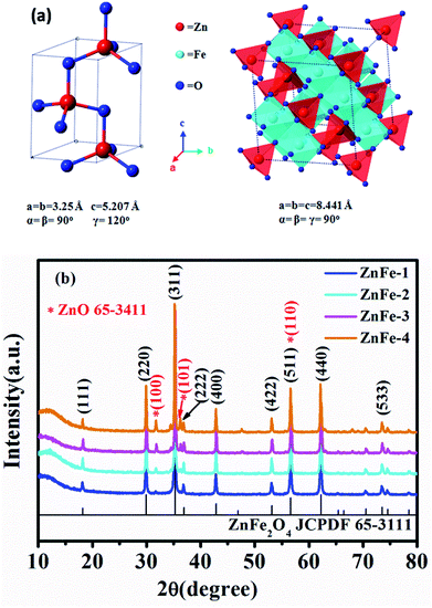 | ||
| Fig. 2 (a) Crystal structure of ZnO and ZnFe2O4. (b) XRD patterns of synthesized ZnO and ZnO–ZnFe2O4. | ||
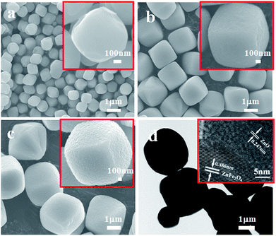
The morphology of the as-obtained ZnO–ZnFe2O4 composites was investigated by SEM and TEM. Fig. 3a–c show that the sample is composed of a number of micro-cubic particles of approximately 1.5 μm in size. The relatively broad size distribution of the micro-cubic particles could be attributed to the overlapping of the nucleation and growth processes at high temperatures with a long time period.25 The 0.247 and 0.486 nm lattice fringes in the ZnFe-3 could correspond to the (101) plane of ZnO and the (111) plane of ZnFe2O4, respectively.
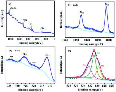
The XPS survey spectrum of ZnFe-3 and the high-resolution spectra of Zn, Fe, and O are shown in Fig. 4. The overview survey confirms the presence of Fe, Zn, and O elements (Fig. 4a). The Zn 2p spectrum displays two peaks at 1045.2 eV and 1022.3 eV with a binding energy of 22.9 eV originating from Zn 2p3/2 and Zn 2p1/2 (Fig. 4b).26 The two main peaks at 725.6 and 711.8 eV can be assigned to Fe 2p1/2 and Fe 2p3/2, and the other two peaks at 734 and 720.4 eV show good agreement with the shakeup satellites.25,27 The high-resolution spectrum of O 1s can be fitted into three peaks. To be specific, the peak at 529.6 eV (O1) can be ascribed to the typical lattice oxygen in the metal (Zn/Fe)–oxygen framework.28 The peak at 530.9 eV suggests the presence of other oxygen composites (O2), such as OH and H2O,29 and the peak at 532.4 eV (O3) can be attributed to a large number of defect sites having low oxygen co-ordination in the ZnO and ZnFe2O4 species.29
The electrochemical performances of the ZnO–ZnFe2O4 micro-cubic composites were first evaluated by CV, which presents a better understanding of the redox reactions and the internal structural transformations occurring during the lithiation–delithiation cycles. The CV curves of micro-cubic ZnFe-3 and ZnFe-1 are shown in Fig. 5. During the first delithiation process, three broad reduction peaks were observed at 1.41, 0.57 and 0.32 V for ZnFe-3 (Fig. 5b). The anodic peak at 1.41 V is attributed to the formation of LixZnFe2O4. The two prominent peaks at 0.57 and 0.32 V can be associated with the reduction of Zn2+ and Fe3+ to metallic Zn0 and Fe0, along with the irreversible decomposition of the electrolyte to form the solid-electrolyte interface (SEI). In subsequent cycles, one main anodic peak shifts to ∼0.91 V, which is due to the structural rearrangement from the pulverization of the composites and the capacity loss which occurs during the process of charging. When the voltage decreases to about 0.05 V, deintercalation of Li+ from the Li–Zn alloy is evident.30
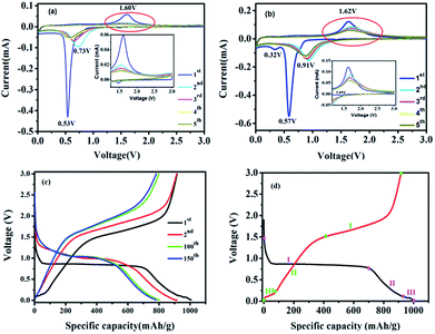 | ||
| Fig. 5 CV curves of ZnFe-1 (a) and ZnFe-3 (b) electrodes. The voltage-specific capacity profiles of ZnFe-3 (c) and the CV of the first cycle for ZnFe-3 (d) at 100 mA g−1. | ||
The broad anodic peak at 0.11 V belongs to the dealloying reaction of Li–Zn, and the one corresponding to ∼1.62 V can be attributed to the reaction of the metallic Zn and Fe into Zn2+ and Fe3+, respectively. During the subsequent cycles, the intensity and integral area of the peak decrease slightly with an increase in the cycling numbers for ZnFe-3, which obviously decreases for bare ZnFe-1 (Fig. 5a). When the voltage corresponding to the range from 1.0 to 3.0 V is enlarged, the intensity of the anodic peaks of ZnFe-1 is found to be almost negligible. These results indicate that the ZnO–ZnFe2O4 hybrid exhibits better electrochemical reversibility than the pristine ZnFe2O4 samples.
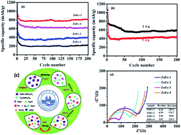
Fig. 6a displays the lithiation/delithiation performance of the ZnO–ZnFe2O4 composite electrode at a current density of 100 mA g−1 in the range 0.01–3.0 V (vs. Li+/Li). The ZnFe-3 exhibits the best electrochemical performance with a high capacity retention and cycling stability. It delivers a superior capacity of 1007/910 mA h g−1 in the first cycle and retains a reversible capacity of 817/811 mA h g−1 even after 200 cycles. The electrochemical performance of the ZnO–ZnFe2O4 composites exhibits a far superior cycling stability compared with the ZnFe2O4 (ZnFe-1). The voltage-specific capacity profiles of ZnFe-3 are shown in Fig. 5c. The irreversible capacity during the initial cycle can be attributed to the formation of an SEI film and an incomplete conversion reaction. The coulombic efficiency of ZnFe-3 is 90.4%, which is a significant improvement over our early ZnFe2O4 systems.31 The first charge/discharge profile of ZnFe-3 is shown in Fig. 5d. Both the lithiation and delithiation curves are divided into three parts. The parts labeled I and II in the lithiation/delithiation processes can be assigned to the reaction equations:
| ZnFe2O4 + xLi+ + xe− → LixZnFe2O4, | (1) |
| LixZnFe2O4 + (8 − x)Li+ + (8 − x)e− → Zn + 2Fe + 4Li2O | (2) |
| Li+ + Zn + e− → LiZn. | (3) |
The dealloying reaction of LiZn
| LiZn → Li+ + Zn + e− | (4) |
| Zn + Li2O → ZnO + 2Li+ + 2e−, | (5) |
| 2Fe + 3Li2O → Fe2O3 + 6Li+ + 6e−, | (6) |
The lithiation and delithiation performances of ZnFe-3 at current densities of 1 and 5 A g−1 are shown in Fig. 6b. The electrodes exhibit excellent cycling performances and deliver capacities of 584 and 430 mA h g−1, respectively, after 200 discharge and charge cycles. After the initial cycle, the coulombic efficiency of the ZnFe-3 electrode remains nearly 100%. When the load current density was increased from 100 to 200, to 500, to 1000, and to 2000 mA g−1, the specific discharge capacities of ZnFe-3 were 945, 851, 804, 761, and 654 mA h g−1, respectively. When the current density returned to 100 mA g−1, the specific capacity could recover to 908 mA h g−1 (Fig. S3†). The capability of charge transfer and electrolyte diffusion at the electrode–electrolyte interface is evaluated by EIS. Fig. 6d presents a comparative study of the Nyquist plots for the ZnO–ZnFe2O4 composites in the fresh half-cell. All the curves show a semicircle in the high-frequency region corresponding to charge transfer impendence (Rct) and a straight line in the medium-frequency region for Warburg impendence (Rw), and in the low-frequency region there also exists the solution resistance (Rs). The Rs and Rct values of the composites are significantly improved compared to bare ZnFe-1. ZnFe-3 exhibits lower Rs and Rct in these electrodes, which is consistent with the previous electrochemical results. At the same time, the diffusion coefficient of ZnFe-3 is the largest among all the samples (Fig. S4†). The high specific capacity and rate capability of ZnO–ZnFe2O4 micro-cubic composites may be attributed to the following factors. Firstly, the hetero-structure electrode, composed of materials with different band-gap energies, i.e. n-type ZnO and p-type ZnFe2O4, will enhance the internal electric field at the hetero-interfaces, resulting in an improvement in the surface reaction kinetics and facilitating charge transport to improve the electrochemical activity. Secondly, the combination of dealloying/alloying and conversion reactions in an integrated hetero-structure electrode material will enhance the specific capacity. Thirdly, the hetero-junction between ZnO and ZnFe2O4 ensures high electrical conductivity and superior chemical–thermal stability, thereby improving its rate capability. Lastly, the synthesis strategy comprising crystal-seed induction followed by hydrothermal reactions can optimize the morphology and good dispersion of the bi-functional components on the hetero-interface. The unique composition and hetero-interface structure of the composite improves its electrochemical performances to a great extent.
Conclusions
In summary, a facile marriage of crystal-seed induction and hydrothermal reactions was performed to fabricate ZnO–ZnFe2O4 micro-cubic composites, which were designed as anode materials for LIBs. Benefiting from its unique structure and bi-functional components, the ZnO–ZnFe2O4 micro-cubic composite exhibited outstanding electrochemical performance as an electrode material for LIBs. The as-prepared ZnO–ZnFe2O4 material can retain a specific capacity of 811 mA h g−1 after 200 cycles at a current density of 100 mA g−1. Even at 5 A g−1, the specific capacity can be stabilized at 430 mA h g−1 after 200 cycles. The synthesis strategy of crystal-seed induction to construct different transition metal oxides with distinct band-gap energies into hetero-structures of controllable morphology is favourable for adoption in rational design approaches for obtaining synergetic functionalities of electrode materials for LIBs.Conflicts of interest
There are no conflicts to declare.Acknowledgements
The authors are thankful for the financial support from the National Nature Science Foundation of China (51402096), the Nature Science Foundation of Hubei Province of China (T201517).Notes and references
- T. Sheng, Y.-F. Xu, Y.-X. Jiang, L. Huang, N. Tian, Z.-Y. Zhou, I. Broadwell and S.-G. Sun, Acc. Chem. Res., 2016, 49, 2569–2577 CrossRef CAS PubMed.
- W. Qi, J. G. Shapter, Q. Wu, T. Yin, G. Gao and D. X. Cui, J. Mater. Chem. A, 2017, 5, 19521–19540 CAS.
- Y. X. Tang, Y. Y. Zhang, W. L. Li, B. Ma and X. D. Chen, Chem. Soc. Rev., 2015, 44, 5926–5940 RSC.
- K. Zhang, X. P. Han, Z. Hu, X. L. Zhang, Z. L. Tao and J. Chen, Chem. Soc. Rev., 2015, 44, 699–728 RSC.
- J. J. Zhang and A. S. Yu, Sci. Bull., 2015, 60, 823–838 CrossRef CAS.
- M.-H. Jung, Appl. Surf. Sci., 2018, 427, 293–301 CrossRef CAS.
- J. Deng, X. Yu, X. Qin, B. Liu, Y.-B. He, B. Li and F. Kang, Energy Storage Materials, 2018, 11, 184–190 CrossRef.
- Q. Xie, D. Zeng, Y. Ma, L. Lin, L. Wang and D.-L. Peng, Electrochim. Acta, 2015, 169, 283–290 CrossRef CAS.
- J. Kwon, J.-H. Kim, S.-H. Kang, C.-J. Choi, J. A. Rajesh and K.-S. Ahn, Appl. Surf. Sci., 2017, 413, 83–91 CrossRef CAS.
- H. Cao, S. Q. Zhu, C. Yang, R. Q. Bao, L. N. Tong, L. R. Hou, X. G. Zhang and C. Z. Yuan, Nanotechnology, 2016, 27, 465402 CrossRef PubMed.
- Y. Qu, D. Zhang, X. Wang, H. Qiu, T. Zhang, M. Zhang, G. Tian, H. Yue, S. Feng and G. Chen, J. Alloys Compd., 2017, 721, 697–704 CrossRef CAS.
- X. B. Zhong, Z. Z. Yang, H. Y. Wang, L. Lu, B. Jin, M. Zha and Q. C. Jiang, J. Power Sources, 2016, 306, 718–723 CrossRef CAS.
- J. G. Kim, Y. Kim, Y. Noh and W. B. Kim, RSC Adv., 2014, 4, 27714–27721 RSC.
- L. Y. Nie, H. J. Wang, J. J. Ma, S. Liu and R. Yuan, J. Mater. Sci., 2017, 52, 3566–3575 CrossRef CAS.
- L. R. Hou, L. Lian, L. H. Zhang, G. Pang, C. Z. Yuan and X. G. Zhang, Adv. Funct. Mater., 2015, 25, 238–246 CrossRef CAS.
- J. H. Kong, X. Y. Yao, Y. F. Wei, C. Y. Zhao, J. M. Ang and X. H. Lu, RSC Adv., 2015, 5, 13315–13323 RSC.
- D. Zhao, Y. Xiao, X. Wang, Q. Gao and M. Cao, Nano Energy, 2014, 7, 124–133 CrossRef CAS.
- L. Yin, S. Chai, J. Huang, X. Kong and L. Pan, Electrochim. Acta, 2017, 238, 168–177 CrossRef CAS.
- S. Liu, R. Wang, M. Liu, J. Luo, X. Jin, J. Sun and L. Gao, J. Mater. Chem. A, 2014, 2, 4598–4604 CAS.
- D. Q. Zhu, F. C. Zheng, S. H. Xu, Y. G. Zhang and Q. W. Chen, Dalton Trans., 2015, 44, 16946–16952 RSC.
- J. Y. Cheong, C. Kim, J.-W. Jung, K. R. Yoon and I.-D. Kim, J. Power Sources, 2018, 373, 11–19 CrossRef CAS.
- X. J. Lu, A. Xie, Y. Zhang, H. C. Zhong, X. C. Xu, H. Z. Liu and Q. S. Xie, Electrochim. Acta, 2017, 249, 79–88 CrossRef CAS.
- A. V. Radhamani, K. M. Shareef and M. S. R. Rao, ACS Appl. Mater. Interfaces, 2016, 8, 30531–30542 CAS.
- X. Hou, J. Feng, X. Xu and M. Zhang, J. Alloys Compd., 2010, 491, 258–263 CrossRef CAS.
- Z. Xing, Z. Ju, J. Yang, H. Xu and Y. Qian, Nano Res., 2012, 5, 477–485 CrossRef CAS.
- Y. Wang, D. Li, Y. Liu and J. Zhang, Electrochim. Acta, 2016, 203, 84–90 CrossRef CAS.
- X. Yang, H. Xue, Q. Yang, R. Yuan, W. Kang and C.-S. Lee, Chem. Eng. J., 2017, 308, 340–346 CrossRef CAS.
- Y. Sharma, N. Sharma, G. V. S. Rao and B. V. R. Chowdari, Electrochim. Acta, 2008, 53, 2380–2385 CrossRef CAS.
- L. Lian, L. Hou, L. Zhou, L. Wang and C. Yuan, RSC Adv., 2014, 4, 49212–49218 RSC.
- D. Zhou, H. Jia, J. Rana, T. Placke, T. Scherb, R. Kloepsch, G. Schumacher, M. Winter and J. Banhart, Electrochim. Acta, 2017, 246, 699–706 CrossRef CAS.
- Y. Ding, Y. Yang and H. Shao, Electrochim. Acta, 2011, 56, 9433–9438 CrossRef CAS.
Footnote |
| † Electronic supplementary information (ESI) available: XRD pattern of the ZnO seed, SEM images of the ZnO seed and ZnFe-3-raw. See DOI: 10.1039/c8ra01785a |
| This journal is © The Royal Society of Chemistry 2018 |


